 Manuel Coca-Gonzalez1
 Sergio G. Torres-Cedillo2
 Mariel Alfaro-Ponce3
 Jacinto Cortés Pérez2
 Paulina Díaz-Montiel4
 Moises Jimenez-Martinez1*
- 1Tecnologico de Monterrey, School of Engineering and Sciences, Puebla, Mexico
- 2Centro Tecnológico FES Aragón, Universidad Nacional Autónoma de México, Nezahualcóyotl, Mexico
- 3Tecnologico de Monterrey, Institute of Advanced Materials for Sustainable Manufacturing, Monterrey, Mexico
- 4Department of Mechanical Engineering, University of San Diego, San Diego, CA, United States
Additive Manufacturing has become a vital component of the global economy, revolutionizing manufacturing processes, enhancing mechanical components, and addressing current industry challenges such as increasing production rates. This study explores the tensile strength and stiffness of 3D-printed Onyx, focusing on the effects of printed perimeter layers. Results show that increasing perimeter layers enhances tensile strength by thickening external walls and improving stress distribution. Experiments demonstrate improvements between 2 and 15 layers do not exceed 20%, and perimeter layers show no impact on toughness. Also, internal infill patterns and density play a more significant role in overall strength once sufficient perimeter layers are in place. Two layers are typically sufficient to ensure cohesion, minimize deformation, and prevent micro-crack propagation. Onyx’s nylon matrix and carbon fibers further improve durability by mitigating stress concentrations in the transition zone between the perimeter and inner layers. However, beyond a certain point, additional layers yield diminishing returns, primarily increasing material consumption without significant strength gains. These findings support future research into additional properties like shear strength and impact resistance while balancing performance, material use, and sustainability.
1 Introduction
In recent years, additive manufacturing (AM) has garnered significant attention as an innovative and versatile production method. This method was defined in (Rasiya et al., 2021) as the manufacture of components by depositing material layer by layer on a base or substrate or without it. Additionally, it is described as creating an object from a three-dimensional model through the successive deposition of material layers.
AM is an increasingly important manufacturing process in different industries that enables the production of highly customized items tailored to specific needs in different industrial applications. It is already important in sectors such as the medical industry. There is also a growing demand in other industries such as automotive (Muvunzi et al., 2021) and aerospace (Khorasani et al., 2021), where it has been used to produce lightweight parts with high structural performance that contribute to reducing weight and improving vehicle performance (Bari and Bollenbach, 2022).
In this context, the novel 3D printing material Onyx
The 3D printing process used to manufacture Onyx components is based on the Fused Filament Fabrication (FFF) method. To initiate this process, a thermoplastic is heated to a temperature just below its melting point and then extruded through a nozzle into the print bed. The nozzle initially generates the perimeter of the component and subsequently fills each layer with patterns chosen by the user. This process is repeated several times, printing one layer at a time, until the desired component is achieved.
It is also important to mention that the mechanical properties of components made with Onyx can be enhanced by adding reinforcing fibers, creating Fiber Reinforced Plastics (FRP). These reinforcements can be Kevlar, glass, or carbon fibers. Reinforcement can be applied at the user’s discretion using a process called Continuous Fiber Reinforcement (CFR). CFR acts as a complementary assembly in the FFF process by adding continuous fibers to the 3D-printed component. It requires a second nozzle to incorporate the continuous fiber reinforcement strands during the conventional FFF process (Kumar and Kruth, 2010).
Due to the recent creation of this material, several studies have reported different techniques to contribute to the understanding of its mechanical properties. As reported in Vanaei et al. (2022), some mechanical properties of the material were calculated by tensile tests. In the case of this study, there were no significant effects on the mechanical properties by varying the fabrication temperature conditions. In contrast to Piramanayagam et al. (2021), Lin et al. (2024) reported a characterization of the mechanical properties by changing layer design patterns hexagonal, rectangular, and triangular and infill densities of 30%, 40%, and 50%. Mechanical (tensile and impact) properties of the printed specimens were conclusively analyzed. From their results, it was observed that better qualities were achieved with an increased infill density, and the rectangular-shaped design exhibited an optimum or maximum tensile strength.
There are other reported works (Krzikalla et al., 2022; Eren et al., 2023) that focused on determining mechanical properties under flexural and compression conditions. In these studies, different reinforcement configurations were employed in the specimen considering quantity and location. Similarly, Al Rashid and Koc (2021) evaluated the behavior of Onyx during creep and stress relaxation tests, but in this case, the tests were performed on specimens made entirely of Onyx, without any reinforcement. The results indicated a significant reduction in maximum and residual strains with the introduction of fibers. However, at higher temperatures, the creep resistance of all materials, including those with reinforcement, was adversely affected.
In Cofaru et al. (2022), the mechanical properties of components made of Onyx with different reinforcements are calculated, using a higher reinforcement volume fraction than the pure Onyx material. In Lee et al. (2023), Furkan Polat and Yilmaz (2022), the influence of the number of reinforcement layers and their position is evaluated under tensile loading conditions. In the case of Hetrick et al. (2020), the impact of the reinforcement volume fraction on Young’s modulus is analyzed by optical microscopy and experimental analysis. It was found that as the amount of fiber increased so did Young’s modulus, UTS, and maximum supported load. On the other hand, the location of the reinforcement layers can cause different types of failure in the component depending on their location. These works focus on analyzing the reinforcement materials, which is their main objective, leaving the influence of Onyx itself in second place.
A notable aspect of the manufacturing process for this material is the limited number of variables that can be controlled due to the constraints of the printer and its associated software. However, studies such as (Sága et al., 2020; Prajapati et al., 2021; Silvestri et al., 2023) analyze the influence of the printing pattern, one of the few parameters available for user control. Another adjustable parameter is the reinforcement volume fraction, which is determined by the component’s infill percentage, as demonstrated in Hetrick et al. (2020) and Maier et al. (2022). Additionally, the position of elements on the printer bed can be specified, as discussed in Maier et al. (2022). This allows users to evaluate whether this parameter affects the mechanical properties of the printed elements.
Two strands of the analysis of the mechanical properties of Onyx have been stated so far. The study of the variables of the manufacturing process and that of the variables in the experiments. We start from the first one to analyze if the number of perimeter layers in the components manufactured only with Onyx, without reinforcement, is a relevant variable or not to be taken into account as a design factor. This variable is deliberately defined by the user and it is common practice to use the default value given by the printing software. The values to choose from range from one to fifteen layers of perimeter.
This research fills a gap in the research on the effect of the number of perimeter layers on the tensile strength and stiffness of 3D-printed Onyx specimens through experimental tests.
2 Methods
2.1 Effective elastic properties of composite materials
This subsection provides the fundamental theory of composite materials used to approximate the effective elastic engineering modulus.
It is possible to determine the longitudinal
To obtain an equation for calculating the elastic modulus in each longitudinal and transverse direction, a perfect bonding between reinforcement and matrix must be assumed, that the fibers show an orthotropic behavior, and the matrix is an isotropic material. Therefore, there are Equations 1, 2 to estimate the longitudinal and transverse modulus of the composite, respectively:
Additionally, the effective engineering modulus of a lamina of arbitrary orientation can be determined from the elastic constants of the lamina in the longitudinal and transverse directions and the orientation angle of the fibers, where it is defined as
Given the volume fraction of the micro carbon fibers relative to the nylon matrix, the rule of mixtures presented in Equations 1, 2 can be used to estimate the longitudinal and transverse moduli of an Onyx coupon of simple geometry. However, these equations will greatly overapproximate the actual properties due to the inability to incorporate the effect of directionality of the printed filaments and defects in between layers on the mechanical properties. Similarly, the effective engineering modulus of a 3D printed Onyx coupon that considers multiple layers of different orientations can be approximated with Equations 3, 4. Yet, using these equations, it is impossible to include the effect of the perimeter layers on the effective engineering moduli of the 3D coupon. Therefore, the most reliable approach to obtain and characterize these properties is through experimental testing (Askeland et al., 2022; Gay, 2023).
2.2 Materials and manufacturing
Unreinforced Onyx is used to fabricate coupons of [0°/90°] and stacking sequence. Table 1 lists the main mechanical properties of Onyx.
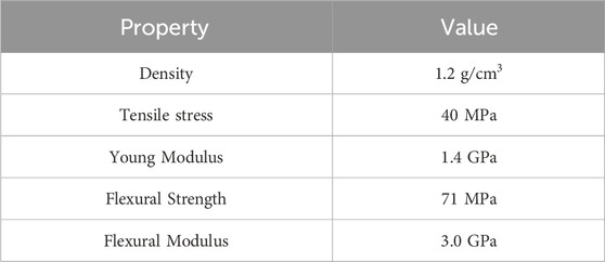
Table 1. Onyx mechanical properties (Vaško et al., 2020) (Almeida et al., 2023).
The printing process employs the fiber deposition technique, where the base material is heated to its melting point. Once this point is reached, the material is extruded through a nozzle and deposited according to user-defined patterns, layer by layer, until the desired geometry is achieved. This fabrication method starts by printing the layers along the perimeter first. Afterward, the interior space is filled by depositing layers in a user-specified orientation. This study examines the impact of the number of perimeter layers and the fiber orientation sequence on the Young’s modulus of the specimens.
A Markforged Mark Two FDM-3D printer is used to manufacture the specimens (Figure 1). It is also used the fiber deposition technique as the method for printing. Table 2 shows the principal printing parameters during this process.
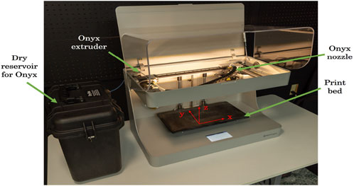
Figure 1. Markforged mark two FDM-3D scheme.
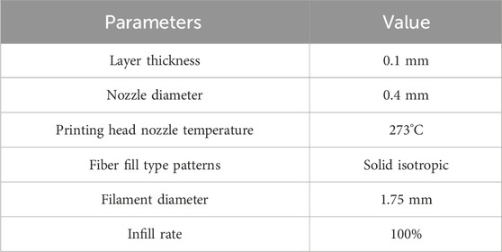
Table 2. Markforged Mark Two FDM-3D printing parameters.
For this study, three different specimen configurations were fabricated. The first configuration considers a stacking sequence [0°,90°] and one perimeter layer of reinforcement as shown in Figure 2. Figure 3 shows the second configuration, also with a stacking sequence [0°, 90°] and two perimeter layers. Finally, the third configuration, shown in Figure 4, consisted of 15 perimeter layers, covering nearly the entire geometry of the specimen.
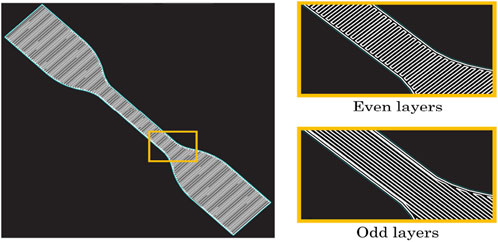
Figure 2. ASTM D638 standard type IV, configuration #1.
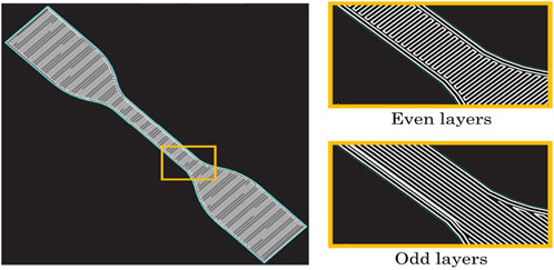
Figure 3. ASTM D638 standard type IV, configuration #2.
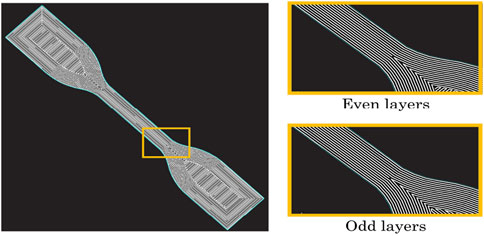
Figure 4. ASTM D638 standard type IV, configuration #3.
On these figures, the top view of the specimen is shown, zooming in on the area of interest of the analysis to exemplify the position of the printed filaments as a function of their location relative to the thickness. For all cases, there are two types of layers, the even and the odd ones, since all the even ones are equal, and all the even ones are equal. Table 3 lists the printing parameters obtained during manufacturing, while the dimensions of the specimens are based on ASTM D638 standard (International, 2015).
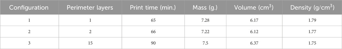
Table 3. Print properties for each configuration of specimens.
These numbers of perimeter layers were selected because, according to the printing software, one layer is not adequate as it shows a warning during the printing process. A two-layer setup is recommended for most components; 15 layers is the maximum number allowed by the software. Comparing these configurations provides a comprehensive understanding of the impact of printer perimeter layers on the elastic properties of 3D-printed components.
The number of perimeter layers and the stacking sequence were selected based on the printing software since there are not many parameters that can be controlled. For example, software is not allowed to create components without perimeter layers. Additionally, the individual orientation of each layer cannot be freely chosen by the user, as the printing process only permits layers with perpendicular orientations to one another. Consequently, creating a symmetric stacking sequence is not feasible.
The specimens are designed by using computer-aided drawing software and then exported to the printing software where the process parameters listed in Table 2 are defined. The dimensions of the specimens to be used are based on the Type IV geometry of the ASTM D638 standard, with a nominal thickness per layer of 0.1 mm and 40 layers stacked with different orientations, giving a final thickness of 4 mm. The layer thickness and the stacking sequence [0°/, 90°] 20 are defined for all the specimens, while the number of perimeter layers is different for each configuration.
2.3 Experimental methods
The specimens were tested in tension at a 5 mm/min rate specified in the ASTM D638 standard on an INSTRON 600DX universal testing machine. This standard was selected because the Onyx manufacturer, Markforged, specifically recommends this standard when evaluating material properties without reinforcing fibers, as mentioned in their material datasheet (Markforged, 2022). Three tests were conducted for each of the three configurations.
There are dimensions for each type of specimen. In this case, those belonging to type IV used in this study are shown in Figure 5. With a distance between the grips (L) of 65 mm. And a distance of 33 mm. For the length of the narrow section (D).
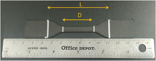
Figure 5. Dimensions for testing specimens according with ASTM D638 standard.
The specimens are mounted on the universal testing machine, and due to their size, they must be preloaded with a force varying between 150 and 200 N. Figure 6 showsa specimen installed and ready for testing. Additionally, the speed chosen to perform the tests is based on the provision of the standard to force the time of each test not to exceed 10 minutes to obtain consistent results.
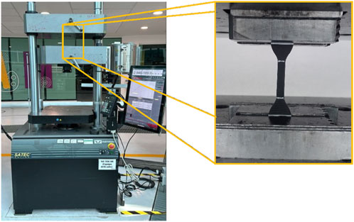
Figure 6. Preconditions before the beginning of the experiment.
3 Results and discussions
Figure 7 shows the stress-strain curve, of all the Onyx specimens tested. From these results, it is pertinent to highlight some observations from the different specimen configurations.
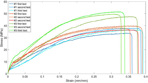
Figure 7. Stress vs Strain comparison configurations #1, #2 and #3.
First of all, it is necessary to mention that by using a filling percentage of 100% and the same printing pattern for all the specimens, the aim is to individualize the modifications in the perimeter layers to show whether or not there is a clear influence on the mechanical properties. Adding or removing perimeter layers is an intentional alteration to the print pattern. Since the software does not allow editing of most of the parameters, it is relevant to look for ways to analyze possible variables in the 3D printing of this material. There is research directly related to this point, Eren et al. (2023), and Anbalagan et al. (2023) analyze the influence of printing patterns on mechanical properties, both in tension and bending. An important finding is that symmetrical sequences yielded better results.
From the results obtained through the experiments, it is evident that configuration #3 specimens have the highest load-bearing capacity because most of the printing pattern is aligned to the longitudinal axis and the perimeter layers extend into the gauge region. This finding is consistent with Piramanayagam et al. (2021) and Nikiema et al. (2023).
Another important finding is that the load-displacement curves for configurations #1 and #2, exhibit similar behavior as was expected, due to their comparable printing patterns. However, differences emerge between in their stress-strain responses. It is evident that increasing the number of layers in the perimeter slightly increases the load capacity and the UTS. In terms of deformation and displacement values, no significant differences are observed. However, considerable variability is evident in the strains and displacements at failure across all specimens.
Figure 8 presents two specimen comparisons (configuration #1 and #2) after being tested, where it is noted that the failure shape is practically the same in both cases due to the similarity between the printing patterns. All the other tested specimens failed similarly, as shown in Figure 9. This is relevant since it is possible to note that the number of perimeter layers does not have a direct influence on the type or region of failure.
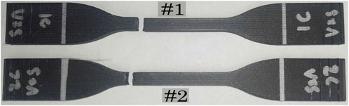
Figure 8. Comparison of fracture in specimens configuration #1 and #2.
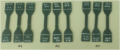
Figure 9. Specimens after being tested.
Table 4 presents the individual results of each test. It is observed from this table that the specimens of configuration #3 withstand a higher peak load and their modulus of elasticity is the highest as well. This is attributed to the alignment of the printing pattern with the axial load applied in the tests throughout the entire thickness and gauge region. According to Equation 3, as the fibers are oriented along their longitudinal axis, there is no need for axis transformation, thus preserving the highest properties.
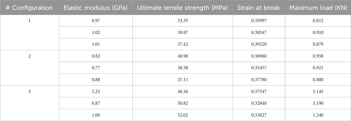
Table 4. Properties obtained for each specimen configuration.
From the table, it can also be observed that the configuration #3 specimens show the highest elastic modulus, with a mean value of 1.04 GPa. This value is reasonable, considering the [0°/ 90°] 20 stacking sequence of the samples. The reference value presented in Table 1 showed that the average elastic modulus of Onyx samples of [0°] stacking sequence and similar thickness is 1.4 GPa. Configuration #3 specimens also show the ultimate tensile strength, with a mean value of 50.4 MPa.
The impact of orienting all the perimeter layers in the longitudinal direction is unmistakable, as this configuration exhibits the highest resistance to axial loads. This distinction in behavior is evident in Figure 7 and the failure modes of the specimens.
In other terms, one of the physical parameters used to estimate mechanical strength is hardness. In previous results it was determined that there is a difference in the hardness achieved on the side of the bed and on the side of the print (Jimenez-Martinez et al., 2023). To understand this variation, measurements of hardness Shore D were made, on the bedside, on the print side, and to know the effect of the number of perimeters, measurements were made on the lateral side, as shown in Table 5. To ensure the reliability of the hardness analysis, five measurements were made in each variant of each configuration, considering the mean value as the hardness.

Table 5. Shore D analysis of each configuration.
In the specimens of configurations #1 and #2, a reduction in hardness of approximately 5% was observed between the bed side and the print face. For configuration #3, this difference was less than 1%. When comparing the hardness between the print face and the side face of the same component, differences of 0.8%, 1.94%, and 2.5% were observed for configurations #1, #2, and #3, respectively.
When comparing the respective hardness of the bedside, print side, and side face, configuration #1 showed an increase in hardness on the print side and a reduction on the lateral side of the specimen.
At a macroscopic level, the failure in all configurations is perpendicular to the direction of the load, as is shown in Figure 9. This is due to the print direction described by the raster angle at 45°. This failure propagation coincides with what Nikiema described (Nikiema et al., 2024). However, although Young’s modulus is not affected by the number of contour perimeters, mechanical strength is increased. Figure 10 zooms in on the elastic zone of the graph. Where it is observed that a stable behavior is maintained in all the tests. This behavior is independent of the perimeter layers. When making the transition to the plastic zone differences in behavior start to be seen.
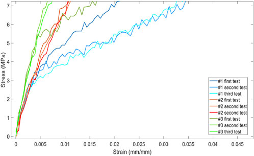
Figure 10. Zoom to the elastic zone.
Since 3D-printed components behave like composite materials, the layers can be analyzed as plies. To correlate mechanical properties with failure characteristics—such as nucleation, interlaminar and intralaminar propagation, or delamination—the components are further examined at a microscopic level.
Figure 11 shows the image analysis. In all three configurations, the failure originated after the perimeter. A generalized brittle and ductile behavior is observed with a contour layer (Figure 3), and reinforced fibers break along the direction of the load. In Figure 3, the progression of the intralaminar failure is shown. In the configuration #2, the failure propagates with an inverted V pattern as in metals (Figure 3), both ductile and brittle behavior is observed. The ductile part have shown a separation along the direction of the load (Figure 3). In the case of configuration #3, a brittle behavior is observed in Figure 3. The mechanical strength is increased by a mean value of 36.65%, but the deformation is reduced. The failure propagates suddenly in an interlaminar fashion on the printed layers, as is shown in Figure 3.
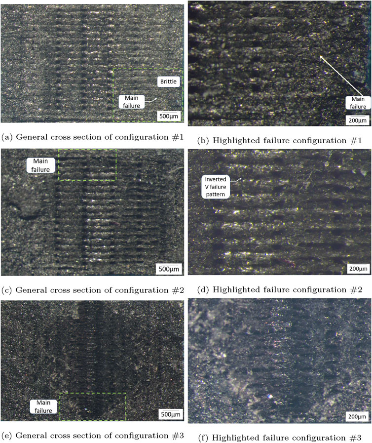
Figure 11. Micrographic results in stereomicroscope. (A) General cross section of configuration #1. (B) Highlighted failure configuration #1. (C) General cross section of configuration #2. (D) Highlighted failure configuration #2. (E) General cross section of configuration #3. (F) Highlighted failure configuration #3.
Even though the three specimen configurations are made of the same material, number of layers and printing parameters (i.e., printing time and temperature), it is evident that the number of perimeter layers highly affects the stiffness and strength. It can be concluded that increasing the layers at the perimeter proportionally influences the load supported by the component and its mechanical properties. Therefore, the necessary perimeter layers that best suit the application should be calculated depending on the expected application.
4 Conclusion
This study focused on the experimental characterization of tension strength and stiffness of 3D-printed Onyx. The effect of the printed perimeter layers on these mechanical properties has been studied. Since closed-form solutions for estimating the mechanical properties of Onyx materials that consider printing parameters do not exist, these investigations can be helpful for the future development of accurate prediction models that incorporate printing processing conditions.
From the results, it is observed that there is higher tensile strength with more perimeter layers. This is because adding more perimeter layers increases the thickness of the external walls and consequently improves the stress distribution during tensile loading. In addition, multiple layers have better adhesion to each other, since all of them share the same nozzle path pattern.
It is important to note that while increasing the number of perimeter layers initially enhances strength, adding too many layers may yield diminishing returns. Once the part thickness becomes sufficient, additional layers primarily increase material consumption without significant gains in strength. This can be seen in Table 4, where the increase in mechanical properties values does not go beyond 20% by comparing 2 and 15 layers. Table 5 shows no evidence that the perimeter layers affect the toughness of the components.
As a result, other printing parameters must also be considered alongside perimeter layers. For instance, strength is influenced not only by the number of perimeter layers but also by the pattern and density of the internal infill. Beyond a certain point, the infill design has a more pronounced impact than the perimeter layers. In practical terms, two perimeter layers are sufficient to maintain correct cohesion throughout the component by maintaining enough space to trace the internal pattern of each layer and generating a resistant contour that is not deformed by external factors. In addition, the cohesion between layers is improved by an adequate number of perimeter layers, which hinders the initiation and propagation of micro-cracks during loading cycles.
On a microstructural level, a transition zone exists between the perimeter and inner layers, where variations in orientation and density can create stress concentrations. However, in Onyx, the nylon matrix and carbon fibers improve the transition, reducing these effects.
More layers provide higher tensile strength, a more robust surface finish, and high structural quality, ideal for components such as lightweight structural supports in the aerospace industry, prosthetics and surgical tools in the medical sector, sensor housings and drone parts in defense, and solar panel mounts in renewable energy. This ensures reliable performance in critical applications where parts must withstand mechanical stress, vibration, or harsh environmental conditions.
Future research could focus on how perimeter layers influence additional mechanical properties, such as shear strength, crucial to prevent failures in connections or joints and impact resistance, critical in applications exposed to shock or vibration. Such research would allow optimal configurations to be identified to maximize mechanical performance based on the specific requirements of each application.
However, it is important to consider the associated trade-offs. Increasing the number of perimeter layers improves properties such as impact, shear strength, and surface finish, but at the cost of increased material and energy use. This can impact the sustainability of printed parts, especially in applications where they are manufactured in high volumes. Therefore, it would be essential to balance the improvement in mechanical performance with resource efficiency and environmental impact, exploring methods that optimize the relationship between durability, material used, and sustainability in 3D printing with Onyx.
Data availability statement
The original contributions presented in the study are included in the article/supplementary material, further inquiries can be directed to the corresponding author.
Author contributions
MC-G: Conceptualization, Data curation, Formal Analysis, Validation, Writing–original draft, Writing–review and editing. ST-C: Methodology, Writing–review and editing. MA-P: Formal Analysis, Writing–original draft, Writing–review and editing. JP: Investigation, Resources, Writing–original draft. PD-M: Formal Analysis, Writing–original draft, Writing–review and editing. MJ-M: Conceptualization, Data curation, Formal Analysis, Methodology, Resources, Supervision, Validation, Writing–original draft, Writing–review and editing.
Funding
The author(s) declare that financial support was received for the research, authorship, and/or publication of this article. This research is partially funded by Lightweight structures lab at Tecnologico de Monterrey Campus Puebla.
Conflict of interest
The authors declare that the research was conducted in the absence of any commercial or financial relationships that could be construed as a potential conflict of interest.
Generative AI statement
The author(s) declare that no Generative AI was used in the creation of this manuscript.
Publisher’s note
All claims expressed in this article are solely those of the authors and do not necessarily represent those of their affiliated organizations, or those of the publisher, the editors and the reviewers. Any product that may be evaluated in this article, or claim that may be made by its manufacturer, is not guaranteed or endorsed by the publisher.
References
Almeida, J. H., Christoff, B. G., Tita, V., and St-Pierre, L. (2023). A concurrent fibre orientation and topology optimisation framework for 3d-printed fibre-reinforced composites. Compos. Sci. Technol. 232, 109872. doi:10.1016/j.compscitech.2022.109872
Al Rashid, A., and Koc, M. (2021). Creep and recovery behavior of continuous fiber-reinforced 3dp composites. Polymers 13 (10), 1644. doi:10.3390/polym13101644
Anbalagan, A., Launchbury, E. J., Kauffman, M., Pazhani, A., and Xavior, M. A. (2023). Investigation on CFRP 3D printing build parameters and their effect on topologically optimised complex models. Mater. Today Proc. doi:10.1016/j.matpr.2023.04.352
Askeland, D. R., Wright, W. J., Bhattacharya, D. K., and Chhabra, R. P. (2022). The science and engineering of materials. Boston, MA: Cengage.
Bari, K., and Bollenbach, L. (2022). Spiderweb cellular structures manufactured via additive layer manufacturing for aerospace application. J. Compos. Sci. 6 (5), 133. doi:10.3390/jcs6050133
Cofaru, N. F., Pascu, A., Oleksik, M., and Petruse, R. (2022). Tensile properties of 3d-printed continuous-fiber-reinforced plastics. Mater. Plast. 58 (4), 271–282. doi:10.37358/mp.21.4.5552
Eren, Z., Burnett, C. A., Wright, D., and Kazancı, Z. (2023). Compressive characterisation of 3d printed composite materials using continuous fibre fabrication. Int. J. Lightweight Mater. Manuf. 6 (4), 494–507. doi:10.1016/j.ijlmm.2023.05.002
Fernandes, R. R., Tamijani, A. Y., and Al-Haik, M. (2021). Mechanical characterization of additively manufactured fiber-reinforced composites. Aerosp. Sci. Technol. 113, 106653. doi:10.1016/j.ast.2021.106653
Furkan Polat, Y., and Yilmaz, V. (2022). Effect of fiber-layer positions on mechanical properties of carbon fiber reinforced materials manufactured by fused deposition modeling. Materiali tehnologije 56 (3), 419. doi:10.17222/mit.2022.419
Hetrick, D. R., Sanei, S. H., Bakis, C. E., and Ashour, O. (2020). Evaluating the effect of variable fiber content on mechanical properties of additively manufactured continuous carbon fiber composites. J. Reinf. Plastics Compos. 40 (9–10), 365–377. doi:10.1177/0731684420963217
International, A. (2015). ASTM d638-14, standard test method for tensile properties of plastics. West Conshohocken, PA: ASTM International. Available at: https://books.google.com.mx/books?id=T0vBuQEACAAJ.
Jimenez-Martinez, M., Varela-Soriano, J., Carreón, J. J. R., and Torres-Cedillo, S. G. (2023). Mechanical fatigue of pla in additive manufacturing. Eng. Fail. Anal. 149, 107273. doi:10.1016/j.engfailanal.2023.107273
Khorasani, M., Ghasemi, A., Rolfe, B., and Gibson, I. (2021). Additive manufacturing a powerful tool for the aerospace industry. Rapid Prototyp. J. 28 (1), 87–100. doi:10.1108/rpj-01-2021-0009
Krzikalla, D., Měsíček, J., Halama, R., Hajnyš, J., Pagáč, M., Čegan, T., et al. (2022). On flexural properties of additive manufactured composites: experimental, and numerical study. Compos. Sci. Technol. 218, 109182. doi:10.1016/j.compscitech.2021.109182
Kumar, S., and Kruth, J.-P. (2010). Composites by rapid prototyping technology. Mater. and Des. 31 (2), 850–856. doi:10.1016/j.matdes.2009.07.045
Lee, G.-W., Kim, T.-H., Yun, J.-H., Kim, N.-J., Ahn, K.-H., and Kang, M.-S. (2023). Strength of onyx-based composite 3d printing materials according to fiber reinforcement. Front. Mater. 10. doi:10.3389/fmats.2023.1183816
Lin, S., Peng, C., Deng, F., Yin, D., and Ye, B. (2024). Influence of structural geometry on tensile properties and fracture toughness in 3d printed novel structures. Eng. Fail. Anal. 161, 108277. doi:10.1016/j.engfailanal.2024.108277
Maier, R., Istrate, A. M., Despa, A., Mandoc, A. C., Bucaciuc, S., and Stoica, R. (2022). Investigation into thermomechanical response of polymer composite materials produced through additive manufacturing technologies. Materials 15 (14), 5069. doi:10.3390/ma15145069
Markforged, Material datasheet, rev 5.2 01/20/2022 (2022). Available at: https://www.markforged.com.
Muvunzi, R., Mpofu, K., and Daniyan, I. (2021). An evaluation model for selecting part candidates for additive manufacturing in the transport sector. Metals 11 (5), 765. doi:10.3390/met11050765
Nikiema, D., Balland, P., and Sergent, A. (2024). Influence of anisotropy and walls thickness on the mechanical behavior of 3d printed onyx parts. CIRP J. Manuf. Sci. Technol. 50, 185–197. doi:10.1016/j.cirpj.2024.03.002
Nikiema, D., Sène, N. A., Balland, P., and Sergent, A. (2023). Study of walls’ influence on the mechanical properties of 3d printed onyx parts: experimental, analytical and numerical investigations. Heliyon 9 (8), e19187. doi:10.1016/j.heliyon.2023.e19187
Piramanayagam, S. R., Kalimuthu, M., Nagarajan, R., Abdul Karim Sait, A. M., Krishnamoorthy, R. K., Ismail, S. O., et al. (2021). Experimental investigation and statistical analysis of additively manufactured onyx-carbon fiber reinforced composites. J. Appl. Polym. Sci. 138 (18). doi:10.1002/app.50338
Prajapati, A. R., Dave, H. K., and Raval, H. K. (2021). Effect of fiber reinforcement on the open hole tensile strength of 3d printed composites. Mater. Today Proc. 46, 8629–8633. doi:10.1016/j.matpr.2021.03.597
Rasiya, G., Shukla, A., and Saran, K. (2021). Additive manufacturing-a review. Mater. Today Proc. 47, 6896–6901. doi:10.1016/j.matpr.2021.05.181
Sága, M., Bárnik, F., Vaško, M., Handrik, M., and Kopas, P. (2020). Identification of physical characteristic of composite materials produced by additive technology from perspective of selected mechanical properties. Acta Phys. Pol. A 138 (2), 249–252. doi:10.12693/aphyspola.138.249
Silvestri, A. T., Papa, I., and Squillace, A. (2023). Influence of fibre fill pattern and stacking sequence on open-hole tensile behaviour in additive manufactured fibre-reinforced composites. Materials 16 (6), 2411. doi:10.3390/ma16062411
Taherzadeh-Fard, A., Cornejo, A., Jiménez, S., and Barbu, L. G. (2023). A rule of mixtures approach for delamination damage analysis in composite materials. Compos. Sci. Technol. 242, 110160. doi:10.1016/j.compscitech.2023.110160
Tam, D., Ruan, S., Gao, P., and Yu, T. (2012). “High-performance ballistic protection using polymer nanocomposites,” in Advances in military textiles and personal equipment (Elsevier), 213–237.
Vanaei, H. R., Magri, A. E., Rastak, M. A., Vanaei, S., Vaudreuil, S., and Tcharkhtchi, A. (2022). Numerical–experimental analysis toward the strain rate sensitivity of 3d-printed nylon reinforced by short carbon fiber. Materials 15 (24), 8722. doi:10.3390/ma15248722
Keywords: additive manufacturing, perimeter layers, fiber orientation, stacking sequence, onyx
Citation: Coca-Gonzalez M, Torres-Cedillo SG, Alfaro-Ponce M, Cortés Pérez J, Díaz-Montiel P and Jimenez-Martinez M (2025) Influence of perimeter layers on tension mechanical properties of 3D printed Onyx. Front. Mech. Eng. 11:1528516. doi: 10.3389/fmech.2025.1528516
Received: 15 November 2024; Accepted: 07 January 2025;
Published: 23 January 2025.
Edited by:
Vinod Ayyappan, King Mongkut’s University of Technology North Bangkok, ThailandReviewed by:
Sohaib Z. Khan, Islamic University of Madinah, Saudi ArabiaSivasubramanian Palanisamy, Kalasalingam University, India
Jayaseelan Veerasundaram, Saveetha Engineering College, India
Copyright © 2025 Coca-Gonzalez, Torres-Cedillo, Alfaro-Ponce, Cortés Pérez, Díaz-Montiel and Jimenez-Martinez. This is an open-access article distributed under the terms of the Creative Commons Attribution License (CC BY). The use, distribution or reproduction in other forums is permitted, provided the original author(s) and the copyright owner(s) are credited and that the original publication in this journal is cited, in accordance with accepted academic practice. No use, distribution or reproduction is permitted which does not comply with these terms.
*Correspondence: Moises Jimenez-Martinez, bW9pc2VzamltZW5lem1hcnRpbmV6QGdtYWlsLmNvbQ==