 B. Vijayaragavan
 M. K. Marichelvam
95% of researchers rate our articles as excellent or good
Learn more about the work of our research integrity team to safeguard the quality of each article we publish.
Find out more
ORIGINAL RESEARCH article
Front. Mech. Eng. , 27 February 2025
Sec. Turbomachinery
Volume 11 - 2025 | https://doi.org/10.3389/fmech.2025.1440903
Labyrinth seals are the non-contact seals used in turbo machinery to control the leakage of the secondary fluid flow. The main compressor supplies the compressed air required to generate hot gases in the combustion chamber. The secondary fluid is the part of the compressed air from the main compressor, which is used for cooling the inner components of turbomachinery. The non-contact nature of the seal results in an additional expense of compressed cooling air, which increases the power input to the main compressor. An improvement in the labyrinth’s sealing efficiency increases turbomachines’ fuel efficiency. The sealing characteristics of the labyrinth profile are highly influenced by the geometric parameters of the labyrinth seal. The geometric parameters of the straight-through labyrinth seal are optimized towards reduced leakage flow, and the optimized parameters are used to develop a new type of “Twin Labyrinth Seal.” The design variables considered in the optimization studies are tooth thickness, cavity width, and cavity depth of the labyrinth, while leakage mass flow rate is the variable to be minimized. Leakage characteristics for different configurations of the twin labyrinth seal are explored using numerical analysis. The standard k-epsilon two-equation viscous model simulates turbulence in the flow through the labyrinth path. The twin labyrinth configuration E with the least leakage is identified with an improved leakage control by 38% compared to the straight-through configuration of the tooth-on stator type. The results from the numerical analysis are validated with experiments. The significance of the effective clearance and divergence angle on the leakage characteristics of the twin labyrinth are discussed.
The performance of the turbo machinery used in power generation and defense equipment is greatly affected by the leakage flow rate through the annular passage between the stator casing and the rotating shaft. The energy efficiency is unsatisfactory because of the higher leakage rate in such components. A reduction of 1% leakage by sealing the high-pressure part of the turbine would decrease fuel consumption by 0.4% (Kaszowski and Dzida, 2015). The leakage can be reduced by increasing the pressure drop between the high-pressure and low-pressure regions, which is accomplished with the help of contact or non-contact seals. Though novel contact seals such as brush seal (Sun et al., 2016) and leaf seal (Nakane et al., 2004) are available, they have issues like friction welding problems and hysteresis of lifting problems due to the rotary nature of the seal component.
Non-contact seals are suitable for application with both rotating and non-rotating components. Out of the numerous types of non-contact seals available, the labyrinth seal is the most popular solution due to its high temperature and pressure capability, high durability, low maintenance cost, and reasonable initial cost. The non-contact labyrinth seals available in practice result from a compromise between the complexity of teeth arrangement and the manufacturing and fabrication technologies available (Li et al., 2006). At each tooth throttling, a portion of the pressure head is converted into mean flow kinetic energy, which is partially dissipated in the cavity just downstream (Rhode et al., 1994a). The seal’s primary use is to lessen or manage internal leakage in pumps, compressors, steam turbines, and gas turbines (Hirano et al., 2005; Yang et al., 2019).
The essential design idea behind labyrinth seals is to use a series of restrictors to create a frictional flow channel between pressure-high and pressure-low zones. The geometric parameters of a straight-through labyrinth seal are shown in Figure 1. The symbol “a” represents tooth thickness, “b” represents cavity width, “c” represents radial clearance and “d” represents cavity depth. The teeth and cavity arrangement in the annular space between the stator casing and the rotating shaft provides numerous re-circulation zones for the leakage fluid where the kinetic energy is lost, resulting in leakage control. Undoubtedly, understanding how the arrangement of teeth affects leakage flow is crucial.
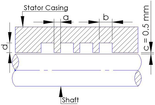
Figure 1. Straight through labyrinth seal.
Many of the previous studies in labyrinth seal present overall pressure drop and leakage flow characteristics only for labyrinth tooth profile machined on either the inner surface of the stator casing (Suryanarayanan and Morrison, 2009; Wu and San Andrés, 2019) or the outer surface of the rotating shaft (Rhode and Adams, 2004). The former is called the Tooth on the Stator (TOS) model, and the latter is called the Tooth on the Rotor (TOR) model. In addition to the above conventional models, the Interlocking type of labyrinth seals (ILS) (Wang et al., 2007) have teeth on both the stator and rotor, as shown in Figure 2. The ILS reduced gas leakage by up to 30% compared to the conventional straight-through designs (Andrés et al., 2019). The study of the leakage characteristics of the interlocking seal by numerical analysis identified the reduction in the leakage by 21% when compared to the Tooth on Stator model seal at a radial clearance of 0.2 mm (Wu and San Andrés, 2018). Similar to ILS, the T-shaped Tooth having Tooth on both the stator and the rotor leaked approximately 25% less than the straight-through labyrinth seal (Jia et al., 2019). Though the ILS model is characterized by improved sealing, their design requires a split case for installation, increasing production and maintenance costs. Hence, there is a need to identify a straight-through configuration with Tooth on both stator and rotor, non-interlocking in nature (Twin labyrinth seal) with improved leakage control characteristics.
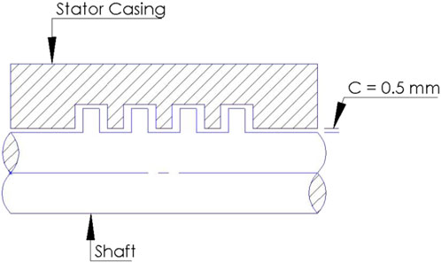
Figure 2. Interlocking seal.
Numerical simulations were performed using ANSYS® Fluent, and the geometric parameters of the straight-through labyrinth seals were optimized to minimize the leakage flow rate and the discharge coefficient. Design optimization of the labyrinth seal was performed using a Large Eddy Simulation, resulting in a leakage reduction of 27.6% compared to the baseline geometry (Tyacke et al., 2021). Optimization of the labyrinth seal geometry of a gas pumping unit was performed using the Gauss-Seidel iteration method (Bellaouar et al., 2013). The geometric parameters of the stepped labyrinth seal were optimized by calculating the leakage rate using Navier Stokes Code, and the optimized model was experimentally tested along with the baseline design (Rhode et al., 1994b). The step position and height of the stepped labyrinth seal were optimized using a simulated annealing optimization algorithm, and the seal geometry was parameterized (Schramm et al., 2004). Pressure drop, temperature differences and maximum temperature are the performance parameters of the cold plate of mini-U channel type which are subjected optimization studies with the help of Response Surface Methodology and non-dominated ranking genetic algorithm. The design variable data required for the studies is obtained from numerical analysis and the input for the analysis is arranged by Box-Behnken design. The reliability of the regression model is verified with the help of Analysis of Variance (Li et al., 2022).
The performance parameters of the micro combustor used in the thermo photovoltaic applications are greatly affected by the design variables like inlet velocity and the tube geometric parameters. Response Surface Methodology combined with non-dominated ranking genetic algorithm is utilized to evaluate the significance of these design variables on the performance parameters through the central composite design (Zuo et al., 2024). The heat transfer and energy consumption characteristics of the cold plate of electric vehicle battery pack are optimized through Response Surface Methodology and non-dominated ranking genetic algorithm. Box-Behnken design is used to develop regression models using the design variables, which includes steady flow velocity, pulsation amplitude and pulsation frequency. Quadratic polynomial form is used to determine the significance of each term by Analysis of Variance (Zuo et al., 2023). Response Surface Methodology with non-dominated ranking genetic algorithm is used to optimize the power density, system efficiency and energy efficiency of the proton exchange membrane fuel cell. Box Behnken design is used to arrive at the combinations of design variables required for the numerical analysis. The design variables considered in the study are operating pressure, operating temperature, anode stochiometry ratio, thickness of the proton exchange membrane and gas diffusion layer porosity (Chen et al., 2023).
The leakage control characteristics of labyrinth seal was improved by optimizing the dimensions and shape of seal teeth for liquid flow conditions (Asok et al., 2007). The numerical and experimental flow investigations of the labyrinth seal with right angle trapezoidal throttle tooth identified the significant effect of the geometric parameters on seal leakage characteristics (Qin et al., 2020). The nozzle structure combined with the labyrinth seal, called Combined Seal Structure (CSS), was developed, and the effect of the geometric parameters on the leakage characteristics was studied by both simulation and experiment (Li et al., 2021). The combination of the inclined labyrinth seal and the honeycomb seal was investigated numerically, focusing on five different parameters affecting the leakage flow (İbrahim Zengin and Erdoğan, 2023). Generally, the geometric parameters considered for the study of leakage characteristics of the labyrinth seal are tooth thickness, cavity width, and cavity depth. In the present work, the above geometric parameters of the straight-through labyrinth seal are optimized. The optimization results are used to develop the twin labyrinth seal configuration and the leakage characteristics of the all the twin labyrinth configurations are compared.
The experimental layout includes the test setup fabricated with mild steel material, a two-stage reciprocating compressor with a storage tank, a control valve between the storage tank and test setup, pressure transducers, and a mass flow meter. Mild steel material is chosen for the fabrication of the test rig due to its machinability and low cost. The pressure transducer used is analog and made of stainless steel. The sensor has a pressure range of up to 12 bar and provides a digital output of 0.5 V–4.5 V, which measures the pressure of the air entering and leaving the test setup. The output signals of the pressure sensor are fed to the system through the Arduino program. The advanced dynamic mass flow meter used in the experiment can detect small changes in the flow, making it suitable for the present work. The layout of the experiment setup is shown in Figure 3.
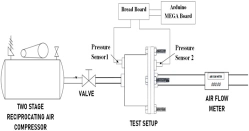
Figure 3. Layout of the experimental setup.
In most previous works, the assumption of a non-rotating test rig gives satisfactory results (Braun et al., 2012; Massini et al., 2014). The study on the influence of rotor speed and circumferential pre-swirl velocity on seal reaction forces showed a strong dependence of reaction forces on the inlet pre-swirl and minimum dependence on the rotor speed (Benckert and Wachter, 1980). When the geometry is fixed, leakage mass flow is more independent of rotational speed (Yar et al., 2019). The static test rig used in the present work consists of a stator with teeth machined circumferentially inside, a central seal carrier with teeth machined circumferentially outside, and a closing lid. The stator is the housing for the seal test rig inside, which allows the central seal carrier to be moved axially for the different configurations of the Twin labyrinth seal. Five different positions are considered, starting from the coincidence of the Tooth of the seal carrier and stator with a clearance of 0.5 mm. The seal carrier is then moved axially by 1 mm for the following consecutive positions. All the five configurations are shown in Figure 4.
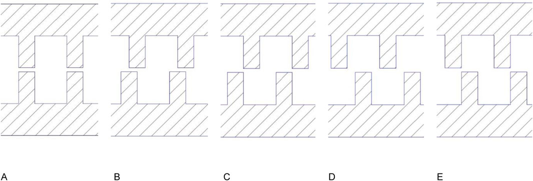
Figure 4. Relative position of the tooth in the configurations (A–E).
The stator has provisions for air entry and pressure measurement on one side. Through holes are provided in the central seal carrier to connect it with the closing lid. The test setup assembly is completed by inserting the central seal carrier connected with the closing lid into the stator. The flanges of the stator and the closing lid are bolted with a gasket in between to prevent air leakage. The air from the compressor enters the test setup through the stator and leaves through the center hole of the closing lid. The closing lid also has a provision for connecting the pressure sensor. The 3D view of the seal test rig components is shown in Figure 5.
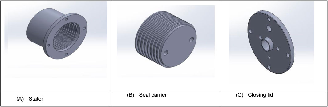
Figure 5. (A–C) 3D view of the seal test rig components.
The pressures upstream and downstream of the test setup are taken as Pin and Pout respectively. The methodology of operational pressure ratio determination (Pin/Pout) is maintained the same in both CFD and experimental methods. The stator’s inner diameter and the seal carrier’s outer diameter are designed to maintain the minimum clearance of 0.5 mm in the flow path, and any deformation in the seal components during the working is negligible. The relative positions are obtained by inserting the suitable numbers of washers in between the seal carrier and closing lid, as shown in Figure 6.
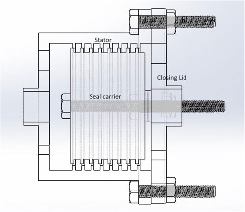
Figure 6. Assembly of the seal test rig components.
Numerical studies in the literature attempted to determine the fluid flow through a simple straight-through labyrinth seal (Wang et al., 2007). CFD simulations applied to practical labyrinth seal configuration aims to expedite sound analytical modelling practice and can be used as a good analysis tool to generate the test data for new seal design studies (Szymański et al., 2018; Asok et al., 2008). In order to reduce the expense and time, conscious engineers used CFD models as a replacement for experimental programs (Andrés et al., 2019). In order to reduce the expense and time, conscious engineers use CFD models as a replacement for experimental programs. The numerical analysis can be carried out by using a 2D flow domain for symmetric flow models (Joachimiak and Krzyslak, 2019; Han et al., 2020), thus reducing the computational effort and calculation time.
In the previous numerical investigations of labyrinth seals, a finite volume computer program is developed to solve the Navier-Stokes equations along with the k-epsilon turbulence model (Stoff, 1980; Zhao and Wang, 2021). k-epsilon turbulent model is identified to be better when compared to other models, including the k-omega turbulent model (Rhode et al., 1986; Zhou et al., 2021). Using a differencing approach decreases false diffusion numerical error and shows that straight-through and stepped labyrinth numerical results agreed well with experiment results (Leonard, 1979). Experiment measurements of the discharge coefficients in straight-through and stepped seals were compared with predictions. For pressure ratios up to 2.5, numerical forecasts and measurements were comparable with each other, which validates the numerical method (Wittig et al., 1987).
The computational region must be meshed up to examine the flow field inside the labyrinth seal profile. The discretization of the flow domain is carried out in the Meshing module of the ANSYS® software. Structured triangular mesh is used with notable refinements to achieve accuracy in specific regions and the growth rate of the discretization is limited to 1.2. Grid Sensitivity test ensures that the results are always independent of mesh. From the grid sensitivity analysis, it is identified that generating mesh with a number of nodes of more than 50,000 will make the analysis results independent of the grid. Mesh is generated only for the sealing flow field; the first layer represents the boundary of the solid wall. The solid part is not considered for the meshing and numerical analysis. The mesh detail of the flow path between the stator casing and the rotating shaft of the straight-through labyrinth seal for a single tooth and cavity is shown in Figure 7.
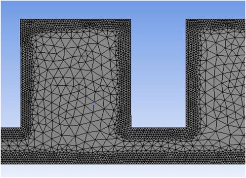
Figure 7. Mesh model showing the triangular elements with wall refinement.
The velocity formulation is taken as absolute, and the standard k-epsilon two equation viscous model is used to simulate the mean flow characteristics for turbulent flow conditions. In the initialization process, the density of the working medium air corresponds to ideal gas condition (Jia et al., 2019). The viscosity of the working medium is calculated by Sutherland equation. The stationary calculations were performed using the Pressure-based coupled solver. In the calculations, a Convergence tolerance of 10–6 is maintained. The seal carrier is assumed to be in the exact center of the stator. Numerical analysis with two-dimensional axisymmetric, turbulent Navier-Stokes code using the finite-volume discretization approach is carried out. The boundary conditions are taken as pressure inlet and pressure outlet (Han et al., 2020). The specification method considered for applying the boundary condition is of “Intensity and Viscosity ratio” type. The values of the turbulent intensity percentage and turbulent viscosity ratio is taken as the default values of 5 and 10 respectively.
The response surface curves for the labyrinth parameters are obtained through the Central Composite Design (CCD), which is based on the Equation 1.
where y is the response variable, b0 is the intercept, bi is the linear coefficient, bii is the quadratic coefficient, bij is the interaction coefficient, Xi is the ith input variable, Xj is the jth input variable, and ε is the error term. Design-Expert® software is utilized to obtain the response surface curves and optimized labyrinth parameters. The set of criteria used in the Design-Expert® is given in Table 1. For generating the leakage mass flow rate data required for optimization, pressure values are considered 4 bar and 1 bar at the inlet and the outlet, respectively. The data set considered for optimization includes 11 center points, 8 factorial points, and 6 star points which are shown in Figure 8.
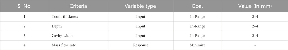
Table 1. Details of the input and response variables.

Figure 8. Optimization data input to the Design-Expert® software.
The present work uses Response Surface Methodology to find the optimized geometric parameters to develop twin labyrinth seal. The minimum value of the generated surface is the leakage mass flow rate, and the independent factors contributing to this minimum flow rate are the optimized parameters of the teeth. The design of experiments is constructed by considering tooth thickness as variable A, cavity depth as B and cavity width as C. The axial length (L) and the seal’s radial clearance (c) are kept constant. The Analysis of Variance (ANOVA) table for reduced cubic model, consolidating the variation in the source terms of the input data is shown in Figure 9. The F-value in the ANOVA table, which is the ratio of the square terms of varying source and error term, shows the existence of the null hypothesis. The P-value of less than 0.05, which is the probability of obtaining extreme F value, indicates statistical significance of the model. The linear distribution of the residuals along a straight line in the normal plot shown in Figure 10 indicates the normal distribution of errors. This implies the adequacy of the proposed model for the present work.
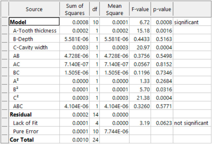
Figure 9. ANOVA table for reduced cubic model.
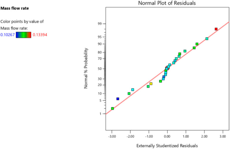
Figure 10. Normal plot of residual for mass flow rate data.
Figure 11 provides the response surface curves for the independent parameters considered concerning the leakage mass flow. From the surface plot of mass flow rate with tooth thickness and depth shown in Figure 11A, it is observed that the increase in the tooth thickness increases the leakage mass flow rate, while increase in the cavity depth does not produce any observable effect on the mass flow rate. From the surface plot of mass flow rate with tooth thickness and cavity width shown in Figure 11B, it is observed that the increase in the cavity width decreases the mass flow rate, while the increase in the tooth thickness causes a very little increase in the mass flow rate. From the surface plot of mass flow rate with cavity depth and cavity width shown in Figure 11C, it is observed that increase in the cavity width decreases the mass flow rate, while the increase in the cavity depth does not produce any observable effect. Thus, the leakage mass flow rate can be minimized by increasing the cavity width and decreasing the tooth thickness. The leakage mass flow rate is independent of the depth. The optimization results are shown in Figure 12. The optimized values for the labyrinth seal geometric parameters are 2 mm, 3 mm, and 3.6 mm for the tooth thickness, cavity depth, and cavity width, respectively. The cavity width is rounded off to 4 mm to avoid manufacturing difficulty. The results are used to develop the new “Twin Labyrinth seal” whose leakage characteristics are determined for different configurations.
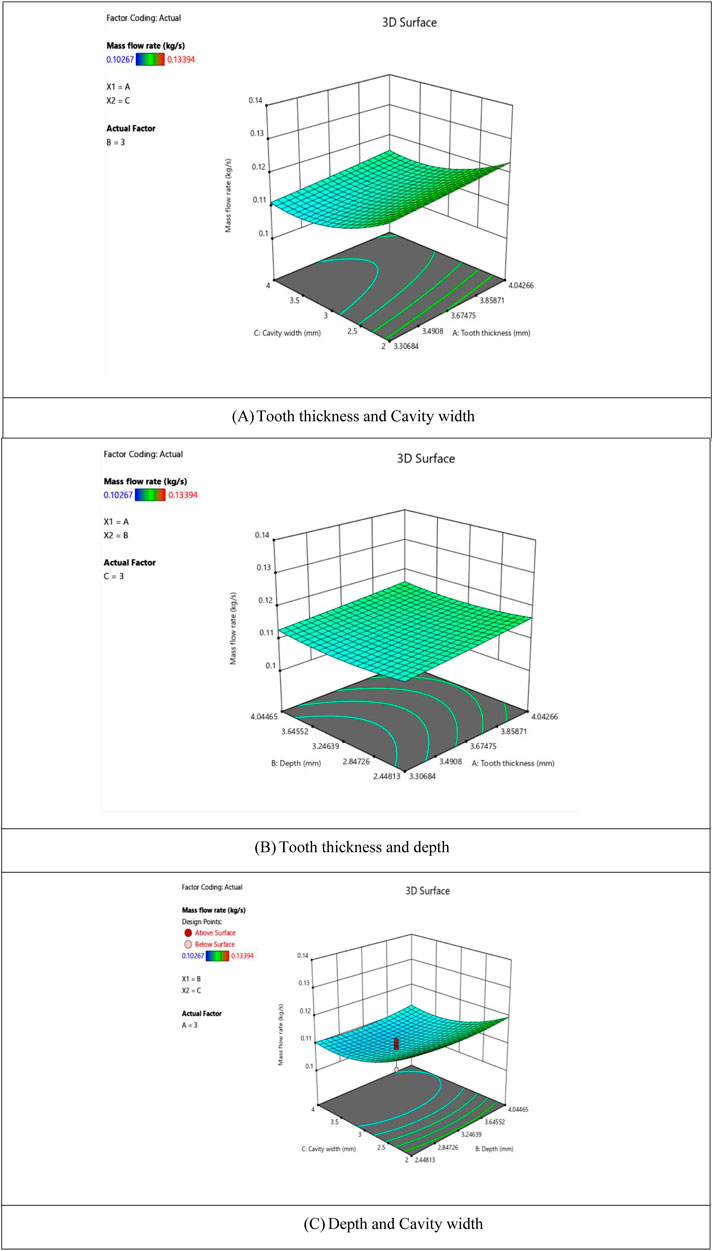
Figure 11. (A–C) Surface plot of mass flow rate vs. independent parameters.
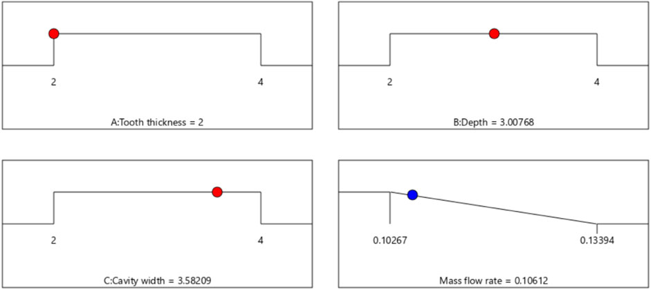
Figure 12. Optimized geometric parameters.
The difference in the leakage mass flow conditions in the axial direction is not only due to the teeth’ shape differences but also the sealing teeth’ arrangement. This is due to the consistency in the sealing principle of the throttling effect followed by vortex energy dissipation in sealing cavities (Jia et al., 2019). Hence, a high-performance labyrinth seal with a new teeth arrangement is necessary for the modern industrialization of turbomachinery systems. In the present work, the effect of the relative position between the Tooth in the stator and rotor is investigated to reduce the leakage rate. The pressure drop occurring due to the expansion of the working medium is graphically compared for all the configurations. The Fluid model replicates the airflow path between the stator and central seal carrier, including the air entry and exit regions. The overall seal length is maintained at 45 mm.
Usually, the Tooth on both the stator and rotor are interlocking in nature in which the Tooth on one side is present inside the cavity of the other side. The fluid path of the interlocking labyrinth seal is highly resistant to leakage fluid flow. A numerical analysis of such an interlocking configuration is carried out, and a reduction in the leakage flow is observed compared to the straight-through configuration. This is followed by the numerical analysis of all five configurations of the twin labyrinth seal. The results are compared with the straight-through and interlocking seal configurations for a pressure ratio of 4, shown in Figure 13. The pressure ratio corresponds to the upstream pressure of 4 bar and downstream pressure of 1 bar, which is the boundary condition considered to obtain the data required for the Design of Experiments.
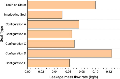
Figure 13. Leakage mass flow rate comparison of seal models.
Configuration E has the least leakage characteristics, which reduces the leakage of the straight-through configuration by 38%. Though the interlocking seal configuration reduces the leakage by 49% than that of the straight through model, the drawbacks in its fabrication and maintenance make configuration E a good alternative. It is identified that configuration B has better leakage control characteristics, next to E. Configuration D leaks more, followed by A, and configuration C is in between A and B. Since the teeth are at the center of the cavity in configuration D, the flow path is highly serpent with increased radial clearance, and the leakage is very high. Configuration A is also not performing well, providing a continuous expansion and contraction similar to an orifice flow. A novel labyrinth seal with a staggered helical teeth structure performs better in reducing leakage when compared to ordinary helical teeth due to the highly induced turbulent energy dissipation in the staggered position (Zhou et al., 2021). A similar staggered condition in configurations B, C, and E improves the seal’s performance compared to configurations A and D. The overall length of the flow is maintained constant for the interlocking, straight-through, and different positions of the twin labyrinth seals to maintain consistency. The pressure drop curves for all the twin labyrinth seal configurations are shown in Figure 14.
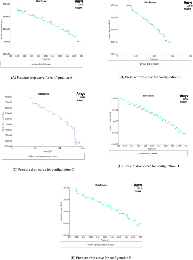
Figure 14. (A–E) Pressure drop characteristics of twin labyrinth seal.
The comparison of the experiment and numerical results of all five configurations at lower pressure ratios are given in Figure 15. All graphs show a strong linear dependence of the leakage mass flow rate with the pressure ratio (Feng et al., 2018). The validity of the numerical model is also ensured through good agreement between the experimental and CFD results. In configuration D, complete turning of the flow is observed where the exit flow has been turned through an angle of 180° from the direction in which it entered the groove. The change in direction does not improve the seal leakage resistance as the flow is not restricted. In contrast to the complete turning of the flow in configuration D, the flow entry in configuration E is not wide enough to allow the complete turning, and the flow trajectory exiting the groove is independent of the flow trajectory entering the groove, making the direction inverse and free flow impossible. Also, in configuration D, the flow clearance is uniform at all the restrictions, which maintains uniform turbulent kinetic energy throughout the flow.
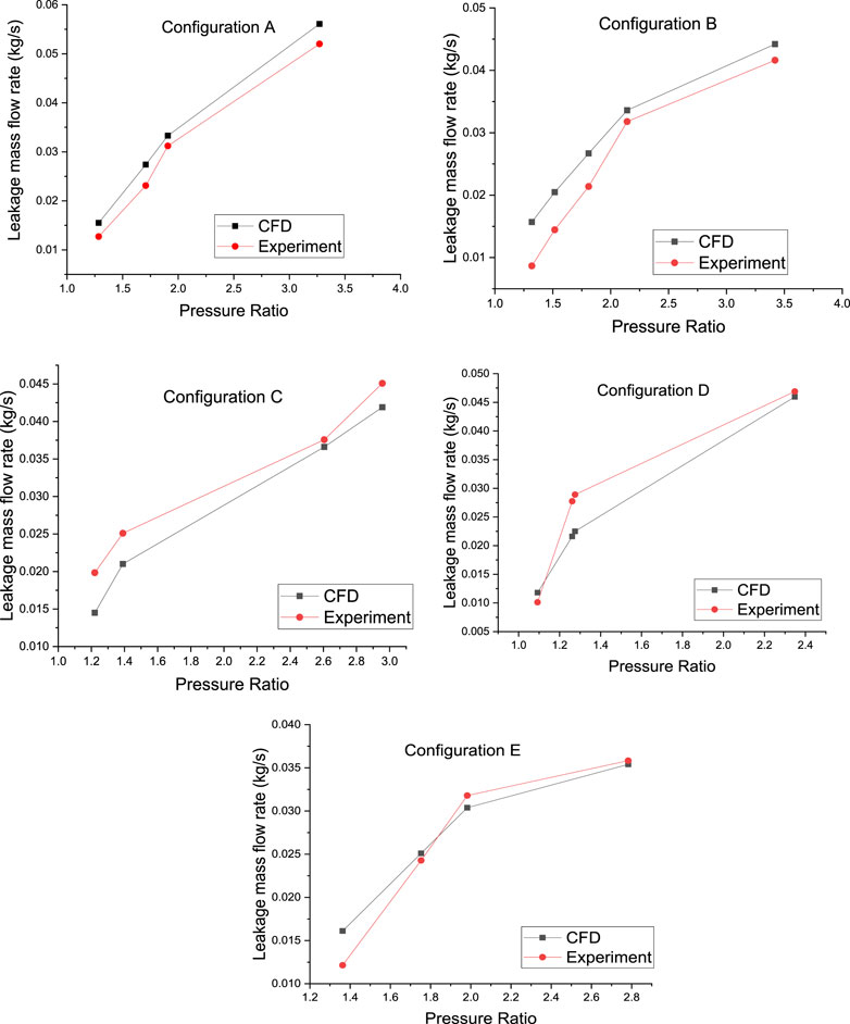
Figure 15. Comparison of results for Configurations (A–E).
In contrast, configuration E has reduced flow clearance alternatively, resulting in the turbulent kinetic energy reaching the peak value in the least clearance, followed by gradual dissipation of kinetic energy before it reaches the least clearance again. Due to the limitation in the flow measurements during the high-pressure conditions during the experimental testing, leakage mass flow rates were not obtained for the high-pressure conditions. Hence, numerical analysis was carried out for the higher-pressure values at both the upstream and downstream locations to study the behavior of all five configurations at increased pressure ratios. The results are shown in Figure 16 which ensure the better sealing characteristics of the configuration E and poor sealing characteristics of the configuration D at various pressure ratios obtained from the measurements during the experimental testing. Though at lower pressure ratios, configurations A, B, and C are having the leakage traits similar to E, the configuration E clearly exceeds them with the increase in the pressure ratio.

Figure 16. CFD results comparison graph.
Effective clearance represents the clearance in a single restriction which provides an equivalent representation of the restrictions throughout the seal length considered in this study (Andrés et al., 2019). Area of flow (A) in a single restriction is represented by
where Rg is the gas constant, T is the ambient temperature and P is taken as the arithmetic average of the upstream and downstream pressures. Substituting density in the expression for leakage mass flow rate,
The effective clearance is given by, Equation 6
When the main flow goes through the clearance, the local turbulent kinetic energy is intensified by the strong velocity gradient which continues as the jet in extended downstream. In the cavities, recirculation is initiated resulting in the dissipation of kinetic energy. The energy dissipation is in the form of heat showing the non-recovery of static pressure as the fluid flows through the neighboring cavity. The static pressure fall is very gradual in the cavity and sharp in the clearance region for configuration A shown in Figure 14A. The pressure fall in the last cavity is significant in configuration B shown in Figure 14B and the same is more significant in configuration C shown in Figure 14C. This dramatic deflection of the bulk flow is clearly visible in the static pressure plot of configuration E shown in Figure 14E. In contrast, Configuration D shows an instant recovery of the pressure in Figure 14D due to the poor arrangement of teeth resulting in the highest effective clearance and leakage flow.
Considering the labyrinth seal construction as a series of orifices and cavities, leakage equation for the seal mass flow is predicted based on discharge co-efficient under each tooth and kinetic energy carry over co-efficient under each cavity (Kaszowski and Dzida, 2015). Increasing the number of teeth reduces the acceleration and static pressure drops in the gaps (Joachimiak and Krzyslak, 2019). But the proposed twin labyrinth model provides a better pressure drop due to orifice effect in each teeth region irrespective of the number of teeth. The turbulent kinetic energy dissipation entering into each individual cavity is quantified by the carry-over coefficient. The relationship between the carry-over coefficient, γ, and the fraction of kinetic energy carried over, χ is
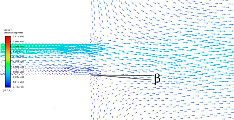
Figure 17. Divergence angle for Configuration A.
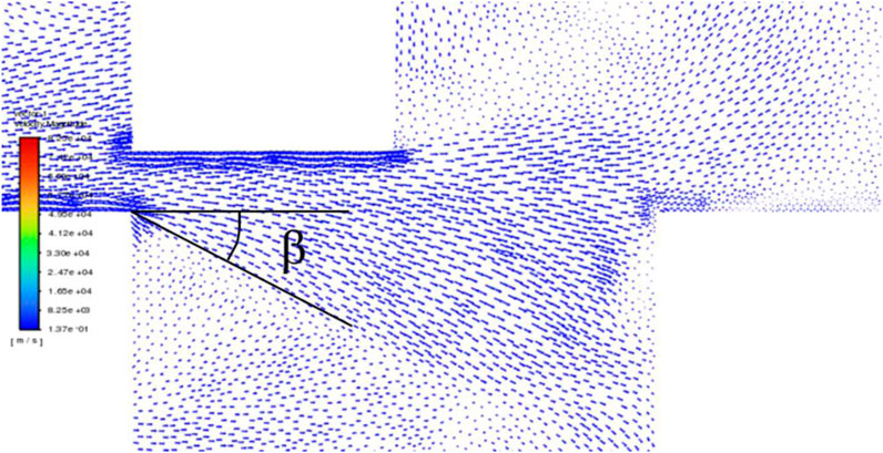
Figure 18. Divergence angle for Configuration E.
In this paper, the geometric parameters of the straight-through labyrinth seal are optimized for improved sealing efficiency. The data required for the optimization are obtained through the axisymmetric numerical analysis carried out by discretizing the labyrinth flow domain with refined triangular grid elements in the ANSYS Fluent® software. The element size of the triangular mesh used for the numerical simulations is determined based on the grid sensitivity test. Optimization and response surface studies are carried out in the Design-Expert® software based on the Central Composite Design (CCD). The data for CCD includes 11 center points, 8 factorial points, and 6 star points. The adequacy of the reduced cubic model used in the study is verified through Analysis of Variance (ANOVA). The statistical significance of the model is ensured through the p-value of less than 0.05. The linear distribution of residuals indicates the normal distribution of errors.
A novel twin labyrinth seal is developed based on the optimization results. The influence of the seal geometry on the leakage rate is given more importance in the earlier works on labyrinth seals. In contrast, the effect of the relative position of the stator and rotor is not considered in the case of Tooth on both the stator and rotor model. The teeth represent the rotor teeth in the static central seal carrier due to the lower leakage dependence on rotor speed. For the first time, the relative positions of the teeth in the static casing and central seal carrier of the twin labyrinth seal are investigated concerning the improvement in the sealing efficiency. The leakage characteristics of the twin labyrinth seal at five configurations are studied by numerical analysis. The pressure drop curve along the clearance space is presented for all the configurations. The experimental set up used in the present work can attain all the configurations. Hence, the numerical analysis results of all the configurations are validated with experiments.
Configuration D has poor sealing characteristics due to the flow-turning phenomenon, which decreases the flow resistance of the seal profile. The semi-empirical term based on Bernoulli’s formula, effective clearance, is defined. The high effective clearance causes the instant recovery of pressure after each throttling in configuration D. This results in high leakage characteristics as the non-recovery of static pressure improves the flow resistance. Configuration E of the twin labyrinth seal has the highest sealing efficiency due to the narrow flow entry region, which is highly resistant to flow turning phenomenon, unlike configuration D. Configuration E has reduced the leakage by 38% compared to the tooth on the stator model. The improved sealing characteristics of configuration E are also due to the flow path with a high divergence angle. The leakage mass flow rate of the complex interlocking seal is found through numerical analysis and compared with the twin labyrinth configurations. Configuration E of twin labyrinth seal can be a potential alternative to the interlocking seal, thus simplifying the fabrication and maintenance.
The original contributions presented in the study are included in the article/supplementary material, further inquiries can be directed to the corresponding author.
BV: Software, Writing–original draft. SPA: Methodology, Project administration, Writing–review and editing. MKM: Investigation, Resources, Writing–review and editing.
The author(s) declare that no financial support was received for the research, authorship, and/or publication of this article.
The authors declare that the research was conducted in the absence of any commercial or financial relationships that could be construed as a potential conflict of interest.
All claims expressed in this article are solely those of the authors and do not necessarily represent those of their affiliated organizations, or those of the publisher, the editors and the reviewers. Any product that may be evaluated in this article, or claim that may be made by its manufacturer, is not guaranteed or endorsed by the publisher.
Andrés, L. S., Wu, T., Barajas-Rivera, J., Zhang, J., and Kawashita, R. (2019). Leakage and cavity pressures in an interlocking labyrinth gas seal: measurements versus predictions. J. Eng. Gas. Turbine Power 141. doi:10.1115/1.4044284
Asok, S. P., Sankaranarayanasamy, K., Sundararajan, T., Rajesh, K., and Sankar Ganeshan, G. (2007). Neural network and CFD-based optimisation of square cavity and curved cavity static labyrinth seals. Tribol. Int. 40, 1204–1216. doi:10.1016/j.triboint.2007.01.003
Asok, S. P., Sankaranarayanasamy, K., Sundararajan, T., Starwin, P., Kalieswaran, R., and Dinesh, M. (2008). Pressure drop characteristics of water flow through static annular and triangular cavity labyrinth seals. Eng. Appl. Comput. Fluid Mech. 2, 482–495. doi:10.1080/19942060.2008.11015246
Baek, S.Il, and Ahn, J. (2021). Optimizing the geometric parameters of a straight-through labyrinth seal to minimize the leakage flow rate and the discharge coefficient. Energies (Basel) 14, 705. doi:10.3390/en14030705
Bellaouar, А., Kopey, B. V., and Abdelbaki, N. (2013). Methods of the rational choice of a labyrinth seal design for gas pumping unit. Mechanika 19. doi:10.5755/j01.mech.19.1.3611
Benckert, H., and Wachter, J. (1980). “Flow induced spring coefficients of labyrinth seals for application in rotor dynamics,” in Ntrs - NASA Technical reports.
Braun, E., Dullenkopf, K., and Bauer, H.-J. (2012). Optimization of labyrinth seal performance combining experimental, numerical and data mining methods. Turbo Expo Power Land, Sea, Air, 1847–1854. doi:10.1115/gt2012-68077
Chen, Z., Zuo, W., Zhou, K., Li, Q., Huang, Y., and Jiaqiang, E. (2023). Multi-objective optimization of proton exchange membrane fuel cells by RSM and NSGA-II. Energy Convers. Manag. 277, 116691. doi:10.1016/j.enconman.2023.116691
Childs, D. W., Elrod, D. A., and Hale, K. (1986). Rotordynamic coefficient and leakage test results for Interlock and Tooth on Stator labyrinth seals. ASME Gas turbine Aeroengine Congr. 1. doi:10.1115/88-GT-87
Feng, J., Wang, L., Yang, H., and Peng, X. (2018). Numerical investigation on the effects of structural parameters of labyrinth cavity on sealing performance. Math. Problems Eng. 1, 1–12. doi:10.1155/2018/5273582
Han, L., Wang, Y., Liu, K., Ban, Z., and Liu, H. (2020). Theoretical modeling for leakage characteristics of two-phase flow in the cryogenic labyrinth seal. Int. J. Heat. Mass Transf. 159, 120151. doi:10.1016/j.ijheatmasstransfer.2020.120151
Hirano, T., Guo, Z., and Kirk, R. G. (2005). Application of computational fluid dynamics analysis for rotating machinery—Part II: labyrinth seal analysis. J. Eng. Gas. Turbine Power 127, 820–826. doi:10.1115/1.1808426
Hodkinson, B. (1939). Estimation of the leakage through a labyrinth gland. Proc. Institution Mech. Eng. 141, 283–288. doi:10.1243/PIME_PROC_1939_141_037_02
İbrahim Zengin, B. E., and Erdoğan, B. (2023). Numerical analysis of geometry and operating conditions in combined honeycomb and inclined labyrinth sealing elements. Prog. Comput. Fluid Dyn. 23, 1–12. doi:10.1504/pcfd.2023.128736
Jia, X., Zheng, Q., Jiang, Y., and Zhang, H. (2019). Leakage and rotordynamic performance of T type labyrinth seal. Aerosp. Sci. Technol. 88, 22–31. doi:10.1016/j.ast.2019.02.043
Joachimiak, D., and Krzyslak, P. (2019). Analysis of the gas flow in a labyrinth seal of variable pitch. J. Appl. Fluid Mech. 12, 921–930. doi:10.29252/jafm.12.03.29074
Leonard, B. P. (1979). A stable and accurate convective modelling procedure based on quadratic upstream interpolation. Comput. Methods Appl. Mech. Eng. 19, 59–98. doi:10.1016/0045-7825(79)90034-3
Li, J., Fu, X., and Yan, S. (2021). Simulation and experimental investigation of a new type of combined seal structure. J. Fluids Eng. 143. doi:10.1115/1.4049678
Li, J., Zuo, W., Jiaqiang, E., Zhang, Y., Li, Q., Sun, K., et al. (2022). Multi-objective optimization of mini U-channel cold plate with SiO2 nanofluid by RSM and NSGA-II. Energy 242, 123039. doi:10.1016/j.energy.2021.123039
Li, Y., Yang, P., Ren, S., and Xu, T. (2006). Hydraulic characterizations of tortuous flow in path drip irrigation emitter* *project supported by the national natural science foundation of China (grant No: 50379053) and the national high Technology development key project (863) (grant No: 2002AA6Z3091). J. Hydrodyn. B 18, 449–457. doi:10.1016/S1001-6058(06)60119-4
Malvano, R., Vatta, F., and Vigliani, A. (2001). Rotordynamic coefficients for labyrinth gas seals: single control volume model. Meccanica 36, 731–744. doi:10.1023/A:1016369408324
Massini, D., Facchini, B., Micio, M., Bianchini, C., Ceccherini, A., and Innocenti, L. (2014). Analysis of flat plate honeycomb seals aerodynamic losses: effects of clearance. Energy Procedia 45, 502–511. doi:10.1016/j.egypro.2014.01.054
Nakane, H., Maekawa, A., Akita, E., Akagi, K., Nakano, T., Nishimoto, S., et al. (2004). The development of high performance leaf seals, 126. The American Society of Mechanical Engineers, 342.
Qin, H., Lu, D., Zhong, D., Wang, Y., and Song, Y. (2020). Experimental and numerical investigation for the geometrical parameters effect on the labyrinth-seal flow characteristics of fast reactor fuel assembly. Ann. Nucl. Energy 135, 106964. doi:10.1016/j.anucene.2019.106964
Rhode, D. L., and Adams, R. G. (2004). Rub-groove width and depth effects on flow predictions for straight-through labyrinth seals. J. Tribol. 126, 781–787. doi:10.1115/1.1760555
Rhode, D. L., Demko, J. A., Traegner, U. K., Morrison, G. L., and Sobolik, S. R. (1986). Prediction of incompressible flow in labyrinth seals. J. Fluids Eng. 108, 19–25. doi:10.1115/1.3242535
Rhode, D. L., Ko, S. H., and Morrison, G. L. (1994a). Experimental and numerical assessment of an advanced labyrinth seal. Tribol. Trans. 37, 743–750. doi:10.1080/10402009408983354
Rhode, D. L., Ko, S. H., and Morrison, G. L. (1994b). Leakage optimization of labyrinth seals using a Navier-Stokes code. Tribol. Trans. 37, 105–110. doi:10.1080/10402009408983272
Schramm, V., Denecke, J., Kim, S., and Wittig, S. (2004). Shape optimization of a labyrinth seal applying the simulated annealing method. Int. J. Rotating Mach. 10, 365–371. doi:10.1155/S1023621X04000375
Stoff, H. (1980). Incompressible flow in a labyrinth seal. J. Fluid Mech. 100, 817–829. doi:10.1017/S0022112080001437
Sun, D., Liu, N.-N., Fei, C.-W., Hu, G.-Y., Ai, Y.-T., and Choy, Y.-S. (2016). Theoretical and numerical investigation on the leakage characteristics of brush seals based on fluid–structure interaction. Aerosp. Sci. Technol. 58, 207–216. doi:10.1016/j.ast.2016.08.023
Suryanarayanan, S., and Morrison, G. L. (2009). Effect of tooth height, tooth width and shaft diameter on carry-over coefficient of labyrinth seals. Proc. ASME Turbo Expo 2009 Power Land, Sea, Air 3, 1147–1152. doi:10.1115/GT2009-59246
Szymański, A., Wróblewski, W., Frączek, D., Bochon, K., Dykas, S., and Marugi, K. (2018). Optimization of the straight-through labyrinth seal with a smooth land. J. Eng. Gas. Turbine Power 140. doi:10.1115/1.4040767
Tyacke, J. C., Dai, Y., Watson, R., and Tucker, P. G. (2021). Design optimisation of labyrinth seals using LES. Math. Model. Nat. Phenom. 16, 2. doi:10.1051/mmnp/2020056
Wang, W., Liu, Y., Jiang, P., and Chen, H. (2007). Numerical analysis of leakage flow through two labyrinth seals. J. Hydrodyn. B 19, 107–112. doi:10.1016/S1001-6058(07)60035-3
Wittig, S., Schelling, U., Kim, S., and Jacobsen, K. (1987). “Numerical predictions and measurements of discharge coefficients in Labyrinth seals,” in Proceedings of the ASME 1987 International Gas Turbine Conference and Exhibition, Anaheim, CA, May 31–June 4, 1987 1.
Wu, T., and San Andrés, L. (2018). Leakage and dynamic force coefficients for two labyrinth gas seals: teeth-on-stator and interlocking teeth configurations. A computational fluid dynamics approach to their performance. J. Eng. Gas. Turbine Power 141. doi:10.1115/1.4041123
Wu, T., and San Andrés, L. (2019). Gas labyrinth seals: on the effect of clearance and operating conditions on wall friction factors – a CFD investigation. Tribol. Int. 131, 363–376. doi:10.1016/j.triboint.2018.10.046
Yang, S., Tan, B., and Deng, X. (2019). Numerical and experimental investigation of the sealing effect of a specific labyrinth seal structure. Math. Probl. Eng. 2019, 9851314. doi:10.1155/2019/9851314
Yar, A., Sohail, Z., Anwar, H., Masud, J., and Toor, Z. (2019). Performance analysis of Labyrinth seals using Analytical methods and Numerical techniques. American Institute of Aeronautics and Astronautics.
Zhao, Y., and Wang, C. (2021). Shape optimization of labyrinth seals to improve sealing performance. Aerospace 8, 92. doi:10.3390/aerospace8040092
Zhou, W., Zhao, Z., Wang, Y., Shi, J., Gan, B., Li, B., et al. (2021). Research on leakage performance and dynamic characteristics of a novel labyrinth seal with staggered helical teeth structure. Alexandria Eng. J. 60, 3177–3187. doi:10.1016/j.aej.2020.12.059
Zuo, W., Li, D., Li, Q., Cheng, Q., Zhou, K., and Jiaqiang, E. (2023). Multi-objective optimization of multi-channel cold plate under intermittent pulsating flow by RSM and NSGA-Ⅱ for thermal management of electric vehicle lithium-ion battery pack. Energy 283, 129085. doi:10.1016/j.energy.2023.129085
Keywords: sealing characteristics, numerical analysis, response surface methodology, effective clearance, divergence angle
Citation: Vijayaragavan B, Asok SP and Marichelvam MK (2025) Optimizing the labyrinth geometric parameters and modelling a new twin seal configuration for improved sealing efficiency in gas turbines. Front. Mech. Eng. 11:1440903. doi: 10.3389/fmech.2025.1440903
Received: 06 July 2024; Accepted: 06 February 2025;
Published: 27 February 2025.
Edited by:
Ellen B. Stechel, Arizona State University, United StatesReviewed by:
Wei Zuo, Wuhan University of Science and Technology, ChinaCopyright © 2025 Vijayaragavan, Asok and Marichelvam. This is an open-access article distributed under the terms of the Creative Commons Attribution License (CC BY). The use, distribution or reproduction in other forums is permitted, provided the original author(s) and the copyright owner(s) are credited and that the original publication in this journal is cited, in accordance with accepted academic practice. No use, distribution or reproduction is permitted which does not comply with these terms.
*Correspondence: M. K. Marichelvam, bWttYXJpY2hlbHZhbW1lQGdtYWlsLmNvbQ==
Disclaimer: All claims expressed in this article are solely those of the authors and do not necessarily represent those of their affiliated organizations, or those of the publisher, the editors and the reviewers. Any product that may be evaluated in this article or claim that may be made by its manufacturer is not guaranteed or endorsed by the publisher.
Research integrity at Frontiers
Learn more about the work of our research integrity team to safeguard the quality of each article we publish.