
95% of researchers rate our articles as excellent or good
Learn more about the work of our research integrity team to safeguard the quality of each article we publish.
Find out more
REVIEW article
Front. Mech. Eng. , 26 June 2024
Sec. Tribology
Volume 10 - 2024 | https://doi.org/10.3389/fmech.2024.1408273
This article is part of the Research Topic Visualization Techniques in Tribology View all 17 articles
Energy-saving technology has become increasingly significant as one of the carbon-neutral options for suppressing recent global warming. Grease-lubricated bearings have been used in various automotive and industrial machinery, requiring low torque and long service life for energy-saving performance, which is greatly influenced by grease fluidity. A numerical approach for understanding grease fluidity is very complex since grease is a non-Newtonian fluid with thixotropic properties. Visualization technique is one of the helpful methods to understand the complex grease fluidity and apply it to practical use. This paper describes state-of-the-art visualization techniques, such as fluorescence method, particle imaging velocimetry, infrared spectroscopy, X-rays, and neutron beams.
The influence of global warming has been serious recently, therefore the environmental preservation programs such as carbon neutrality have been accelerated. The requirements for energy-saving of automotives and industrial machineries have been significant. Among them, rolling element bearings have been used various machineries and required for improvements such as lowering torque and longer service life. Greases are mainly used for lubrication of the bearings and the reduction of energy loss (or torque) caused by grease resistance through bearing rotations could contribute to energy-saving of various machineries. Furthermore, the fluidity of grease affects the service life of bearings, and these factors have been investigated (Vencl et al., 2017; Vasic et al., 2020). Additionally, nanosized additives have been studied to improve bearing lubrication (Abouelkasem et al., 2024; Bukvic et al., 2024).
Nitta et al. (2016) stated that the causes of energy loss in rolling element bearings can be roughly divided into the stirring resistance of lubricants, the viscous rolling resistance, the friction resistance between balls and races, and the friction resistance between balls and cages. It is stated that the stirring resistance is a main factor and largely influenced by grease fluidity in bearings. The grease fluidity can be illustrated by channeling and churning states (Lugt, 2009). In the churning state, a grease is sheared by moving parts such as balls and causes high bearing torque due to drag losses (Hutton, 1975; Lugt, 2016). This continuous grease shearing raises temperature of the bearing. In contrast, in the channeling state, most of grease is pushed away from the running track. The drag losses from grease shearing decrease due to this grease clearing. As a result, the bearing torque reaches steady low values. In the initial phase of a bearing operation, the grease lubricates in the churning state, and a quick transition to the channeling state is promising for developing an energy-saving grease.
For understanding the grease fluidity, it is ideal to visualize grease, especially inside bearings. Papers dealing with the visualization of grease fluidity are limited although those concerning the observation of lubricating oil are more common. This article deals state-of-the-art visualization techniques of grease fluidity, such as fluorescence method, particle imaging velocimetry, infrared spectroscopy, X-rays, and neutron beams. The author hopes that these techniques will enhance the understanding of complex grease behaviors and expedite the development of high-performance greases.
The techniques using fluorescence for the observation of grease fluidity can be roughly divided two types. One is a method using fluorescence particles, and the other is a method using fluorescence dyes dissolved in greases. The former technique is sometimes called PIV (Particle Image Velocimetry). PIV is a fluid visualization technique that involves dispersing tracer particles into a fluid and measuring velocity vectors by capturing the visualized flows. For instance, after dispersing particles that emit fluorescence when irradiated with light of a specific wavelength (fluorescence agent) into an observation target grease, the grease is flowed with irradiation of light containing that specific wavelength and the movement of the generated fluorescence is captured with a high-speed camera. Rhodamine B whose particle size is several to tens of microns can be used as a fluorescent agent Li et al. (2012). Maccioni et al. (2022) and Haruyama et al. (2016) visualized the fluidity of grease in bearings by using bearings with transparent outer rings. Iki et al. (2022), using a ball-on-disk test rig, compared the branch-like patterns (or track patterns) and the flow velocity of greases observed around the running track on the disk as shown in Figure 1, and discussed the correlation between the grease fluidity and the bearing torque behaviors. This method has uncovered the tendencies of thickeners in grease flow; however, the observations were confined to areas outside of the contact point. In other words, it allowed for the observation of grease flows after they had passed the contact point, suggesting that the behaviors within the actual contact area might differ. Instead of PIV using fluorescent particles, Obata and Itoigawa (2022) reported a visualization technique using dye aggregates. They filled greases containing the dye aggregates into bearings and utilized the splitting and coloration of the aggregates caused by the shear generated during bearing rotations to visualize the grease fluidity such as churning and channeling states. This method enabled the visualization of grease shearing within bearings; however, the observation was limited to a side view of the bearing. Consequently, obtaining information about the contact areas still presents some hurdles.
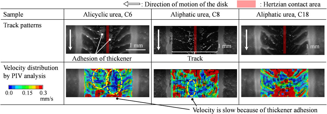
Figure 1. Track patterns and velocity distribution by PIV analyses of each type of urea greases (Iki et al., 2022).
When using fluorescent particles as described above techniques, the particle size is in the micron range, so the techniques visualize the grease fluidity in macro-scale, including relatively thicker films. In contrast, there are also fluorescent dyes that dissolve homogeneously in base oils due to their molecular structures. If sufficient fluorescence intensity is obtained, there is a possibility of visualizing the grease fluidity in micro-scale, thinner film in the vicinity of the contact area. The technique using fluorescent dyes for visualization is known as fluorescent staining and is used for observation of cells in vivo. Therefore, the fluorescent dyes are often expensive and/or water-soluble. Relatively inexpensive oil-soluble fluorescent dyes that can be applied to lubricants are limited, for instance, pyrene and coumarin-6. The former has a low polarity, while the latter has a high polarity, so it is considered to have a high affinity with low-polarity base oils and high-polarity thickeners, respectively. Since pyrene and coumarin-6 have different fluorescent wavelengths, it could be possible to distinguish the fluidity of base oil and thickeners by blending both fluorescent dyes into the grease. Sakai et al. (2016) observed the grease fluidity using pyrene near the contact area in a ball-on-disk test and discussed the correlation with bearing torque. Kostal et al. (2020) quantified the fluorescence intensity and oil film thickness as shown in Figure 2, and visualized the fluidity of grease near the contact area with relatively thick oil film, although it is difficult to quantify the oil film thickness of the contact area due to the low fluorescence intensity. Suzuki et al. (2020) used coumarin-6 and visualized phenomena of the adhesion and delamination of thickeners to the contact areas in a pin-on-disk test. Yamamoto et al. (2020) visualized the grease fluidity near the EHL (Elastohydrodynamic Lubrication) region using pyrene and coumarin-6. The separation of the base oil and thickeners in the grease during rotations and the backflow of the grease in the front of the contact area were observed. Azetsu (2021) applied the photochromism to the visualization of the movement of oil film on the piston lands of an optical engine. That technique utilizes a photochromic dye dissolved in oil. An arbitrary spot of oil is illuminated with ultraviolet light at an arbitrary timing, which makes a marker in the oil film via a photochromic reaction. This technique has a possibility of the application to visualization of grease fluidity.
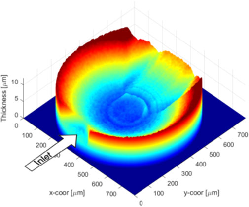
Figure 2. Film thickness evaluation (Kostal et al., 2020).
In the observations using pyrene and coumarin-6 mentioned in the previous section, these observations were focused on the contact area, which is similar to in-situ observation in EHL. There are reports on observation techniques for EHL using FT-IR (Fourier Transform Infrared Spectroscopy) microscopy. In addition to measuring the oil film thickness from the absorbance, information on the chemical structure of the lubricant film present near the contact area can be obtained, allowing for the observation of the concentration ratio of the base oil and thickener. Hoshi et al. (2019); Hoshi et al. (2020) used a ball-on-disk test machine with FT-IR microscopy and confirmed that film thickness of urea grease increased in low-speed ranges and that the thickener is concentrated on the contact area as shown in Figure 3, and discussed the relationship with frictional properties. Mapping with FT-IR microscopy requires a relatively longer duration, for example, 45 s for a line scan, making it challenging to capture grease movement in the vicinity of the contact area within a shorter time span, as is possible with conventional in-situ observations in EHL using optical interferometry.
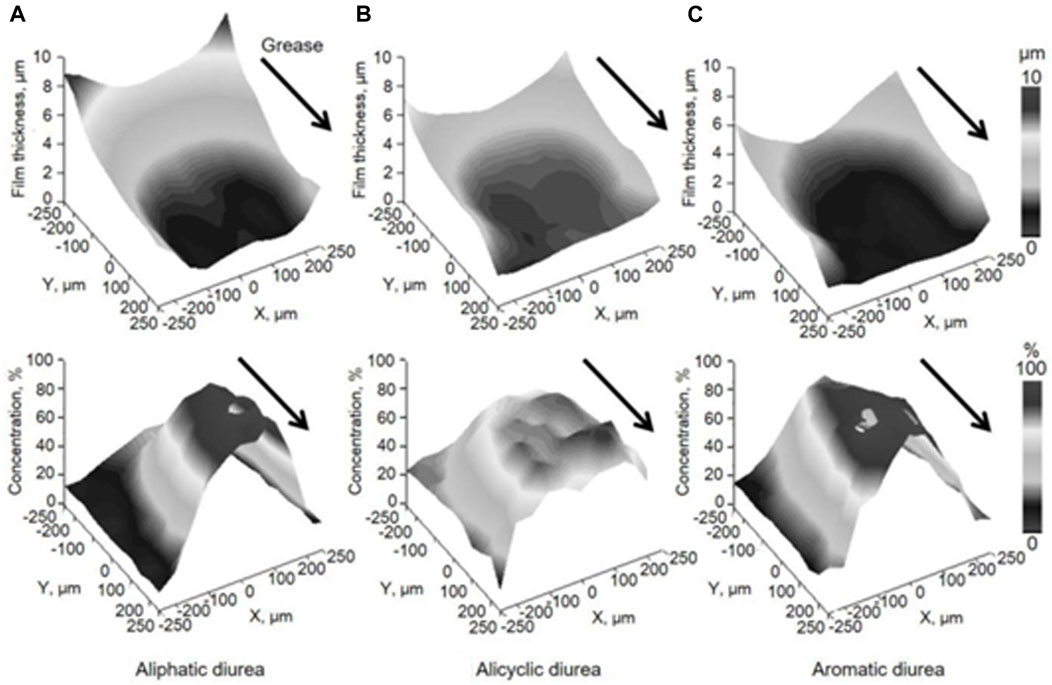
Figure 3. 3D images of film thickness and thickener concentration (Hoshi et al., 2020).
Techniques that use X-rays to visualize the inside of the body, such as X-ray photography for medical purposes, barium tests, and CT (Computed Tomography) scans, are generally well-known, but this technology is also used for visualization of grease. Noda et al. (2020) visualized the differences in the fluidity of urea type and barium soap type greases with different X-ray absorption rates using bearings composed of special fluororesin inner and outer rings and special glass balls to pass X-rays through for visualizing the grease fluidity inside the bearing as shown in Figure 4. Additionally, Noda et al. (2022) used USAXS (Ultra-Small-Angle X-ray Scattering) at the large-scale synchrotron radiation facility SPring-8 to observe changes in the scattering pattern that occur when a Barium soap grease is subjected to shear using a rheometer. It is said that structural changes such as the orientation, destruction, and aggregation of thickeners due to shear can be visualized. 3D X-ray micro-CT observations have also been used to identify grease immobilized into geopolymer mortar paste (Campos et al., 2022).
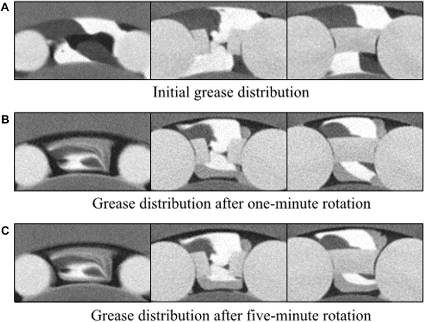
Figure 4. Grease internal flow observed from clipped CT images at three different times (Noda et al., 2020).
X-rays have a stronger interaction with heavier elements. Therefore, when visualizing the fluidity of grease inside a bearing using X-rays, it is necessary to use special bearings that allow X-rays to pass through, as described above. To increase the sensitivity of the grease, it is also necessary to use barium thickened grease instead of lithium thickened grease, which is commonly used as a grease.
The characteristics of neutrons compared to X-rays are as follows. Neutrons have a strong interaction with light elements such as hydrogen, but a weak interaction with heavy elements such as iron. Therefore, neutrons are potentially effective for visualizing grease, since neutrons can penetrate the inner and outer rings of rolling elements bearings composed mainly of iron and are absorbed by grease composed mainly of light elements. In addition, due to the lower energy of neutrons compared to X-rays, it is expected to cause less damage to samples such as grease. Based on these characteristics, neutrons can be a ground-breaking technique of visualizing grease inside normal bearings, and Ito and Nose (2013) reported visualization of grease inside a bearing using neutrons.
Sakai et al. (2021a) used RADEN, a neutron beamline at the Materials and Life Science Experimental Facility (MLF) of J-PARC (Japan Proton Accelerator Research Complex), to visualize the distribution of grease inside a bearing. The lithium (Li)-based greases were selected for evaluation, Li complex type (Grease A) and single Li soap type (Grease B). Prior to the neutron imaging of the bearing filled with grease, a torque test was performed, and it was confirmed that Grease A provided lower torque. Based on this result, it was speculated that Grease A lubricated in a channeling state, while Grease B lubricated in a churning state. To understand the fluidity of the grease in detail, neutron CT imaging was conducted after rotation of the bearing. The axial and radial neutron tomography images of the bearing are shown in Figure 5. The black area indicates a metallic part with low neutron absorption, while the white area indicates the presence of grease or oil with high neutron absorption. Grease A was mainly present on the cage areas, while there was less grease on the cage areas for Grease B. In addition, Grease A showed very little adhesion to the rolling elements, and a gap was confirmed between the inner and outer rings, which corresponds to the channeling state. On the other hand, Grease B showed a lot of adhesion to the rolling elements, which corresponds to the churning state.
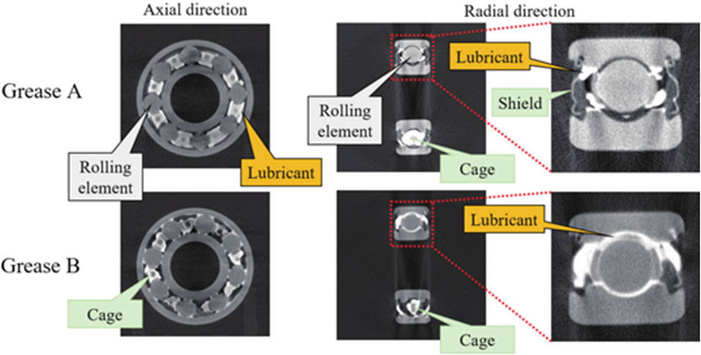
Figure 5. Neutron computed tomography of bearings under grease lubrication after rotation (60 min) (Sakai et al., 2021a).
Although it was observed that Grease B flew throughout the bearing, it is unclear at which rotational speed and duration it started to flow. To understand this, radiography was conducted on the bearing with rotation at each rotation speed (Sakai et al., 2021b). It should be noted that CT observation is not possible with the rotational condition. The neutron radiography images after 5 or 10 min of rotations at each rotation speed are shown in Figure 6. Unlike the previous images, white areas indicate metallic parts with low neutron absorption, while black areas indicate grease or oil with high neutron absorption. In addition, by leaving one of the eight locations in the cages areas unfilled with grease to create a void (white area), it is easier to understand the fluidity of the grease and the rotation of the bearing. For both Grease A and B, the voids remained and greases mainly stayed on the cage areas at 200 and 1,000 min−1. On the other hand, at 2,000 min−1, Grease A maintained the same state as at lower rotation speeds, while in Grease B, the grease spread throughout the entire bearing, and the contrast between the grease and the metallic parts gradually decreased as the void disappeared. After 10 min of rotation, it became difficult to distinguish the void. With pulsed neutrons obtained at J-PARC, it is difficult to obtain clear images due to insufficient irradiation frequency and exposure time relative to the rotation speed of the bearing. However, it is speculated that observation of the fluidity of grease at the macro-scale is possible. Increasing the irradiation frequency of the neutron beam is expected to enable observation at high speeds, and one method to achieve this is to use the facilities at the Japan Research Reactor (JRR-3).
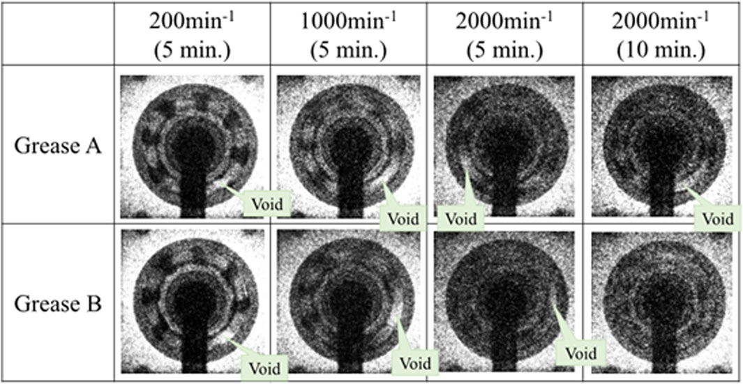
Figure 6. In situ observation of bearings with rotations using neutron radiography for each rotation speed (Sakai et al., 2021b).
Recently, with the electrification of automobiles, the high-speed rotation of bearings used for small and high-output electric motors is required. In order to obtain knowledge of how the grease distribution changes at higher speeds, CT observation was conducted on a 6010 bearing filled with Grease A after rotating it up to 12,000 min−1 (Sakai et al., 2022). The results are shown in Figure 7. The black area indicates a metallic part with low neutron absorption, while the white area indicates the presence of grease or oil with high neutron absorption. With increasing rotation speed, the movement of grease from cage areas to the shield was confirmed. As above mentioned, it was also confirmed that there was little adhesion of grease to the rolling elements. Considering the torque and temperature measured separately during bearing rotation, it is speculated that with the increase in rotation speed of the bearing, the torque first decreases and then the bearing temperature also decreases due to the movement of grease from the cage areas to the shield. It was expected that the adhesion of grease to the rolling elements would have a significant impact on the torque, but it is suggested that the grease present on the cage areas can also be a torque factor at high speeds. Furthermore, visualization suggests that the degree of grease exclusion from the rolling elements and cage areas is significant at high speeds, and there is a high possibility of reaching starvation lubrication.
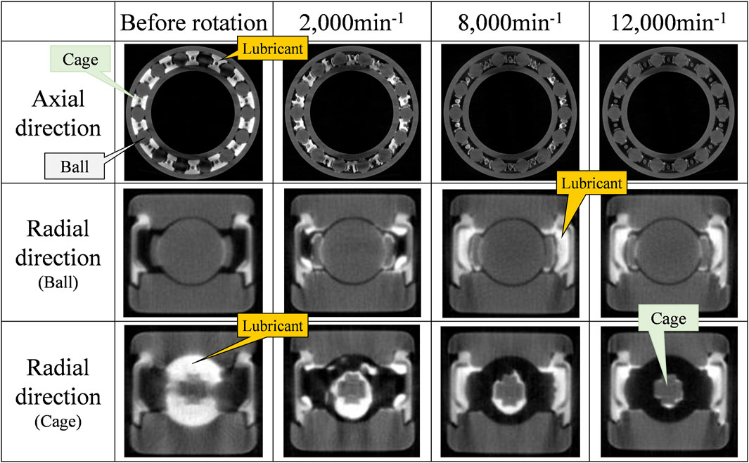
Figure 7. Neutron tomography of bearings before/after rotations (Sakai et al., 2022).
This article reviewed recent visualization techniques for grease, including the use of fluorescence, IR, X-rays, and neutrons as summarized in Table 1. Each technique covers the visualization of limited areas, therefore it is difficult to fully understand the complex flow of grease with only one observation technique. For example, X-ray CT and neutron imaging are effective for understanding bulk grease distribution within machine elements such as bearings. Fluorescence methods can visualize grease flows in the vicinity of the contact areas. Additionally, FT-IR is beneficial for observing EHL to identify the chemical composition of grease around the contact point. Considering the main application of grease for bearings, it is expected that efforts will be made to combine visualization techniques and complementary evaluation methods, and to provide feedback to practical applications. The author hopes that the techniques will contribute not only to the development of grease products but also to achieving carbon neutrality.
KS: Writing–review and editing, Writing–original draft, Visualization.
The author(s) declare that no financial support was received for the research, authorship, and/or publication of this article.
Author KS is employed by ENEOS Corporation.
All claims expressed in this article are solely those of the authors and do not necessarily represent those of their affiliated organizations, or those of the publisher, the editors and the reviewers. Any product that may be evaluated in this article, or claim that may be made by its manufacturer, is not guaranteed or endorsed by the publisher.
Abouelkasem, Z. A., Nassef, G. A., Abdelnaeem, M., and Nassef, M. G. A. (2024). Enhancing the elastohydrodynamic lubrication and vibration behavior of rolling bearings using a hybrid bio-grease blended with activated carbon nanoparticles. Tribol. Lett. 72, 46. doi:10.1007/s11249-024-01847-3
Azetsu, A. (2021). Observation of oil film behavior using photochromic visualization method. J. Jpn. Soc. Tribol. 66 (11), 803. (in Japanese). doi:10.18914/tribologist.66.11_803
Bukvic, M., Gajevic, S., Skulic, A., Savic, S., Asonja, A., and Stojanovic, B. (2024). Tribological application of nanocomposite additives in industrial oils. Lubricants 12 (1), 6. doi:10.3390/lubricants12010006
Campos, M. D., Reeb, C., Davy, C. A., Hosdez, J., and Lambertin, D. (2022). Solidification/stabilization (S/S) of high viscosity organics in geopolymers. J. Nucl. Mater. 571, 153979. doi:10.1016/j.jnucmat.2022.153979
Haruyama, H., Sawada, N., and Nanri, K. (2016). Visualization of grease flow using fluorescent particle -1st: grease flow of bearing race way. Proc. JAST Tribol. Conf. Niigata, B34. (in Japanese).
Hoshi, Y., Takiwatari, K., Nanao, H., and Mori, S. (2020). In situ observation of transient responses in grease lubrication by micro infrared spectroscopy. Tribol. Online 15 (4), 201–208. doi:10.2474/trol.15.201
Hoshi, Y., Takiwatari, K., Nanao, H., Yashiro, H., and Mori, S. (2019). In situ observation of EHL films of greases by micro infrared spectroscopy. Tribol. Online 14 (2), 53–59. doi:10.2474/trol.14.53
Hutton, J. F. (1975). The influence of flow elasticity on the bearing performance of lubricating grease. Proc. JSLE-ASLE Int. Lubr. Conf., 707.
Iki, H., Sakai, K., Hoshino, K., Sato, R., Nishizawa, K., Miwa, R., et al. (2022). Observation of grease fluidity on raceway by particle image velocimetry. J. Jpn. Soc. Tribol. 67 (10), 727. (in Japanese). doi:10.18914/tribologist.22-00007
Ito, A., and Nose, H. (2013). Visualization of grease 3D distribution in rolling bearing by neutron radiography. Proc. JAST Tribol. Conf. Fukuoka, B19. (in Japanese).
Kostal, D., Onitsuka, S., Tanaka, H., Sugimura, J., Krupka, I., and Hartl, M. (2020). Use of pyrene for quantitative fluorescence observation of Li-grease around EHL contacts. Tribol. Online 15 (3), 117–125. doi:10.2474/trol.15.117
Li, J. X., Hoglund, E., Westerberg, L. G., Green, T. M., Lundstrom, T. S., Lugt, P. M., et al. (2012). μPIV measurement of grease velocity profiles in channels with two different types of flow restrictions. Tribol. Int. 54, 94–99. doi:10.1016/j.triboint.2012.03.007
Lugt, P. M. (2009). A review on grease lubrication in rolling bearings. Tribol. Trans. 52 (4), 470–480. doi:10.1080/10402000802687940
Lugt, P. M. (2016). Modern advancements in lubricating grease technology. Tribol. Int. 97, 467–477. doi:10.1016/j.triboint.2016.01.045
Maccioni, L., Chernoray, V. G., Bohnert, C., and Concli, F. (2022). Particle image velocimetry measurements inside a tapered roller bearing with an outer ring made of sapphire: design and operation of an innovative test rig. Tribol. Int. 165, 107313. doi:10.1016/j.triboint.2021.107313
Nitta, M., Tsuda, T., Arai, H., Sakamoto, K., and Sakai, K. (2016). Effects of transition point of viscoelasticity of diurea grease and molecular structure of thickener on running torque of the ball bearing -effects of alkyl chain length of aliphatic diurea-. J. Jpn. Soc. Tribol. 61, 699. (in Japanese). doi:10.18914/tribologist.61.10_699
Noda, T., Shibasaki, K., Miyata, S., and Taniguchi, M. (2020). X-ray CT imaging of grease behavior in ball bearing and numerical validation of multi-phase flows simulation. Tribol. Online 15 (1), 36–44. doi:10.2474/trol.15.36
Noda, T., Takayama, Y., Kuwamoto, S., Sonoda, K., and Washizu, H. (2022). Structural changes of thickener and rheological properties of lubricating greases under shear flow. Proc. JAST Tribol. Conf. Fukui, B36. (in Japanese).
Obata, T., and Itoigawa, F. (2022). Quantitative observation of grease behavior for rolling bearings using splitting phenomena of colorant. J. Jpn. Soc. Tribol. 67 (1), 54. (in Japanese). doi:10.18914/tribologist.21-00012
Sakai, K., Ayame, Y., Iwanami, Y., Kimura, N., and Matsumoto, Y. (2021a). Observation of grease fluidity in a ball bearing using neutron imaging technology. Tribol. Online 16 (2), 146–150. doi:10.2474/trol.16.146
Sakai, K., Iki, H., Ayame, Y., Iwanami, Y., Kimura, N., and Matsumoto, Y. (2021b). Observation of grease fluidity in a ball bearing using neutron imaging technology (Part 2) -in situ observation of bearing with rotation-. Proc. JAST Tribol. Conf. Matsue, D28. (in Japanese).
Sakai, K., Ogata, R., Kimura, N., and Matsumoto, Y. (2022). Observation of grease fluidity in a ball bearing using neutron imaging technology (Part 3) -effect of rotation speed. Proc. JAST Tribol. Conf. Fukui, C5. (in Japanese).
Sakai, K., Tokumo, Y., Ayame, Y., Shitara, Y., Tanaka, H., and Sugimura, J. (2016). Effect of formulation of Li greases on their flow and ball bearing torque. Tribol. Online 11 (2), 168–173. doi:10.2474/trol.11.168
Suzuki, M., Maruyama, K., Ando, T., Monna, T., Arakawa, K., and Takeichi, Y. (2020). Behavior observation of grease thickener during compressing and initial sliding using fluorescence microscopy. Proc. JAST Tribol. Conf. Beppu, F40. (in Japanese).
Vasic, M., Stojanovic, B., and Blagojevic, M. (2020). Failure analysis of idler roller bearings in belt conveyors. Eng. Fail. Anal. 117, 104898. doi:10.1016/j.engfailanal.2020.104898
Vencl, A., Gasic, V., and Stojanovic, B. (2017). Fault tree analysis of most common rolling bearing tribological failures. IOP Conf. Ser. Material Sci. Eng. 174, 012048. doi:10.1088/1757-899x/174/1/012048
Keywords: grease, imaging, bearing, channeling, churning, neutron, particle imaging velocimetry, fluorescence
Citation: Sakai K (2024) Visualization techniques of grease fluidity. Front. Mech. Eng 10:1408273. doi: 10.3389/fmech.2024.1408273
Received: 28 March 2024; Accepted: 03 June 2024;
Published: 26 June 2024.
Edited by:
Taisuke Maruyama, NSK Ltd., JapanReviewed by:
Milan Bukvic, University of Kragujevac, SerbiaCopyright © 2024 Sakai. This is an open-access article distributed under the terms of the Creative Commons Attribution License (CC BY). The use, distribution or reproduction in other forums is permitted, provided the original author(s) and the copyright owner(s) are credited and that the original publication in this journal is cited, in accordance with accepted academic practice. No use, distribution or reproduction is permitted which does not comply with these terms.
*Correspondence: Kazumi Sakai, c2FrYWkua2F6dW1pQGVuZW9zLmNvbQ==
Disclaimer: All claims expressed in this article are solely those of the authors and do not necessarily represent those of their affiliated organizations, or those of the publisher, the editors and the reviewers. Any product that may be evaluated in this article or claim that may be made by its manufacturer is not guaranteed or endorsed by the publisher.
Research integrity at Frontiers

Learn more about the work of our research integrity team to safeguard the quality of each article we publish.