
95% of researchers rate our articles as excellent or good
Learn more about the work of our research integrity team to safeguard the quality of each article we publish.
Find out more
ORIGINAL RESEARCH article
Front. Mech. Eng. , 08 August 2023
Sec. Digital Manufacturing
Volume 9 - 2023 | https://doi.org/10.3389/fmech.2023.1232562
 Daniel P. da Silva1
 Joao Pinheiro1
 Saba Abdulghani1Christina Kamma-Lorger2Juan Carlos Martínez2Eduardo Solano2Artur Mateus1
 Paula Pascoal-Faria1
 Geoffrey R. Mitchell1*
Direct digital manufacturing has been identified as one of the key tools of Industry 4.0 and it enables the creation of products directly through digital definition. Commonly known as additive manufacturing, it comprises a set of technologies that are expressively agile in small-scale productions and prototyping, in comparison to conventional mass manufacturing processes, such as injection molding of plastics. It streamlines mass customization, allows the production of highly complex objects, and has been broadly applied in several fields, from medical devices to the aerospace industry. Although a new era of design possibilities and accessibility was unveiled, most developments are focused on shape reproduction precision and the development of new feeding systems and materials. This work is focused on a shift in design for additive manufacturing, where the polymer properties, by means of the adjustment of the process conditions (extrusion rate, the write speed, and the nozzle temperature, among others), constitute a decision-making variable. In order to evaluate the morphology of semicrystalline polymers during extrusion-based 3D printing, in-situ time-resolving small and wide-angle X-ray scattering measurements were performed at the ALBA synchrotron light source in Barcelona (Spain). The goal of this research is to develop a material property mapping methodology during semicrystalline polymer melt extrusion-based 3D printing Some experiments were performed with low-density polyethylene, and we were able to confirm a correlation between the extrusion rate and writing speed of the printing with the level of preferred orientation of the chain folded lamellar crystals in the extrudate.
Direct Digital Manufacturing (DDM) consists of a decentralized scheme of manufacturing where designers and individuals (as consumers and makers) conceptualize products and innovative solutions allowing them to obtain small batches and mass customization for end users, making use of additive manufacturing as a base of the spectrum of technical solutions in which is possible to obtain final parts and prototypes directly from a computer-aided design (CAD) file within a digital network and, optionally, validated through computer-aided engineering (CAE) software (Chen et al., 2015; Gibson et al., 2015; Paritala et al., 2017).
In comparison to conventional manufacturing technologies, DDM has enabled a more agile exploration of complex designs, and prototyping has become much faster and less expensive. Moreover, it has been established in industrial and commercial low-volume productions, and for customized tools (e.g., jigs, fixtures) (Paritala et al., 2017). It is assumed that scientists and engineers have another set of technical solutions when designing for manufacturing, especially while working on complex and optimized geometries, engineered with topology optimization, generative design, or, simply, different infill strategies.
The advantage of mass customization is also beneficial for biomedical applications, where doctors and engineers combine strategies to create custom-fitting products for patients, such as in regenerative medicine, cancer therapies, and drug delivery systems (Morouço et al., 2015).
Additive manufacturing (AM) comprises a variety of materials and processes, with extrusion-based technologies (such as FDM™/FFF - fused deposition modeling ™/fused filament fabrication) being the most accessible and popular solutions. Usually fed with filaments containing thermoplastic polymers, FDM™/FFF equipment heat the material above the melting point, extrude it, and deposit it layer by layer, in predetermined patterns onto a build platform and predecessor layers, in order to complete a certain geometry (Turner and Gold, 2015; Kristiawan et al., 2021).
In the last few years, many advances in 3D printing have been achieved, such as: object shape reproduction with higher accuracy (geometric and dimensional); higher print speeds (Duan et al., 2018); feeding systems along with material selection; and component integration (Durakovic, 2018). The range of available materials has followed this trend, widening to respond to the functionality requirements of the manufactured parts, including fiber reinforcement (Fico et al., 2022).
Attention has been given to the process parameters, such as printing temperatures and velocities, in order to optimize the polymer melt flow rate (Woern et al., 2018). Besides that, there is an awareness of the influence of the manufacturing variables on the mechanical properties of the printed parts, as with any polymer processing technology (Kristiawan et al., 2021). In some cases, in situ X-ray scattering analysis was performed along the printed layers, comparing the crystallization at different heights of the deposited strands, but lacking the evaluation along the write (print) direction with the variation of the fundamental processing parameters (Nogales et al., 2019; Ezquerra et al., 2022). In a similar way, but with the combined assessment of the temperature profile of the print, this technique was also used to infer the influence of the temperature profile on the degree of crystallinity (Shmueli et al., 2019). However, there is not a focus on the material design itself, beyond the domain of geometry replication.
The aim of this work is to address this area, introducing a new stage of design for additive manufacturing (DfAM). Ideally, the material properties can be mapped on demand along an entire part, through the control of the process parameters. The properties of semicrystalline polymers such as LDPE are determined as much by the morphology of the semicrystalline polymers as the chemical configuration of the polymer, fixed in the material during polymerization. The challenge consists of understanding the correlation between the control inputs and the physical properties of the parts. This is the focus of this work, in which fused granular fabrication was used to perform printing trials with distinct sets of parameters, while analyzing the morphology development of the polymer melt using X-ray scattering; and in line with the previously reported work (da Silva et al., 2022; Silva et al., 2022).
Small-angle X-ray scattering (SAXS) addresses the length of 10–50 nm, and thus, is able to provide quantitative detail on the size of the chain folded lamellar and the nature of the preferred orientation of these lamellar. Time-resolving SAXS is able to follow in real time the transformation of a polymer melt into a semicrystalline morphology, and will reveal details of this transformation process which will not be possible to determine from scattering data on the final products at room temperature. Wide-angle X-ray scattering (WAXS) is used to determine the crystal structure and the fractions of differing phases present at any specific time. Analysis of the WAXS in conjunction with SAXS will determine the shape of the chain-folded lamellar crystals in terms of any twisting during growth, etc.
Fused granular fabrication (FGF) (or fused particle fabrication) (Woern et al., 2018) is an extrusion-based process that uses plastic pellets instead of a filament as the feedstock. In practice, it is a suitable approach for the production of bigger parts, and for the exploitation of the materials available on the market (typically deployed in injection molding) or custom composites.
Usually, virgin material is obtained in pellet shape, and the same happens with recycled materials. Obtaining filament rolls implies an additional step, where the material is extruded with a certain diameter (usually 1.75 mm or 3 mm) and then wound. This filament production process might result in a slight degradation of the material, which can be considered a disadvantage of filament-fed 3D printers (Cruz Sanchez et al., 2017; Mikula et al., 2021). Besides, the use of pellets is very straightforward, and associated extrusion systems permit a relatively constant extrusion rate (with an even flow of homogeneous melt and without material feed blockages).
This work is based on a pellet-fed production, and, despite the availability of a large number of materials, and their grades, in this shape for injection molding, as an example; the successful implementation in 3D printing with melt deposition is deeply compromised by an elaborated set of distinct parameters and conditions, in comparison to conventional production technologies. In other words, the availability of a wider range of materials does not immediately mean that the pellet-shaped raw matter can be suitable for 3D printing. Instead, it means their potential applicability can be studied and explored. The FGF 3D printers share the same platforms FDM™/FFF printers, the only difference re-lies on the feeding/extruder system. Instead of a filament intake mechanism for the material to be pushed through a hot end, the extruder has a pellet hopper or a melt reservoir, to store and furtherly introduce the material in a solid or liquid state respectively, in the extruder barrel with a rotating extrusion screw (Almeida et al., 2010; Whyman et al., 2018; Shaik et al., 2021). An alternative approach consists of filling a chamber with granules and utilizing a piston to press the heated material (Volpato et al., 2015). The representation of these configurations can be observed in Figure 1.
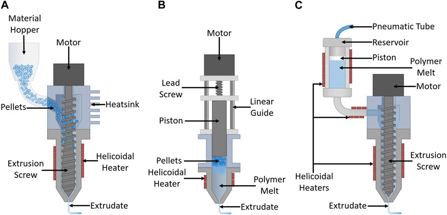
FIGURE 1. Representation of the types of fused granular fabrication extruders. (A) extruder chamber directly fed with pellets; (B) pellets placed and melt in the piston/plunger chamber; (C) pellets placed and melt in the reservoir.
Basically, material feeding can occur in two ways: directly loading the extruder with pellets or loading it with the polymer melt.
In configuration a), from the reservoir, the beads enter the extrusion chamber (by gravity, or compressed air, and the motion of the screw itself), which has to be cooled to allow the transportation, at the feed zone, of the plastic material to the heated part where it is compressed and melt.
Configuration b) requires a full retraction of the piston to allow the refill of the chamber, the pellets are then compressed and melted in the same extruder part.
With configuration c), the material is placed and heated in a separate reservoir. The transport of the polymer melt is done by means of the movement of a piston, loaded with compressed air. Notice that this configuration has three main heating zones: feeder, channel, and extruder body. Therefore, despite guaranteeing a uniform flow rate of material, this adds variables to control, to a list of parameters commonly involved in this form of additive manufacturing.
• Feeding system
oGravity
oSize of the beads
oAir pressure
oChamber heating
oPolymer rheology
• Extruder temperature
oHeating power
oInsulation
oThermal conductivity and Heat dissipation of the extruder’s body
oCooling system
• Extrusion rate/speed
oFeeding system
oPower input and mechanical transmission
oCompression ratio
• Write/Print speed
oPower input and mechanical transmission
oVibrations and damping
oMechanical elements and movement precision
oWrite/print and extrusion speed function (Geng et al., 2019)
oAdhesion to bed/platform or to the previously deposited layers of material
• Printing platform/bed
oLevelling
oPlatform material and finishing (for adhesion and/or heat conduction)
oBed temperature
• Nozzle/hot end configuration
oDiameter
oLength
⁃ Length-to-diameter ratio
oTemperature
oMaterial of the nozzle body
oGeometry of the nozzle body
• Material
oRheology
⁃ Viscosity and melt flow index (MFI)
⁃ Temperature
⁃ Pressure
oThermal conductivity of the extrudate
oTemperature differential between the layers
• Cooling system
oExtrusion temperature
oThermal conductivity of the extrudate
oTemperature of bed/platform or previously deposited layers of material
• Surrounding environment
oEnclosure hermeticity
oAmbient temperature (air and radiant temperatures in closed and open environments)
oHeat and matter transfer (air draughts and convection influence)
oHumidity
Exploring materials limits in 3D printing requires a set of instruments in order to monitor, control, and contour the above-listed variables (the levels of the list express the dependencies of each main parameter).
The time response of the input parameters differs between them, and for an “on demand” and “on the fly” control, it is rather convenient to have a practically instantaneous transition of the real value to the successive setpoints. Beyond that, the property mapping depends on the time it takes for the parameter shifts to have an effect on the material morphology, and the amount of time for relaxation and/or crystallization. The importance of these factors lies in the resultant precision and resolution of the induced property texture into the object’s material.
In practice, when set and read from the g-code file, a shift in extrusion rate or print speed happens substantially quicker than with the extrusion temperature. Not only this last variable has a noticeable delay associated, but it also has a more unstable behavior with successive heating and cooling switches around the target value, within a certain interval (overshooting and undershooting).
Although an effective extrusion temperature control could be employed, this paper focuses on the changes in the writing and extrusion speeds. Still, there are limitations such as the overall maximum velocity of the process, related to the mechanical transmission, and the movement precision or induced vibration.
The variety of pellet-shaped materials available in industry, such as several types and grades of polyolefins and polyesters, is directly obtained from chemical synthesis (virgin plastics) and recycling plants. In fact, the usage of recycled polymers in 3D printing has been investigated in order to reduce the environmental impact associated with “post-petroleum plastic sources” (Mikula et al., 2021). Following this trend, this type of manufacture constitutes a possible promotor of the circular economy. This becomes effective by reintegrating the most widely used polymers in the first phases of the plastic value chain described by (Johansen et al., 2022).
One of the most ubiquitous plastics is low-density polyethylene (LDPE). This polyolefin is mainly present in packaging, pipes, and houseware items, and is part of the seven main groups of recycled plastics (Achilias et al., 2007; Mikula et al., 2021). The use of LDPE in direct digital manufacturing is still very limited and challenging due to issues such as poor adhesion and high shrinkage (Olesik et al., 2019; Verma et al., 2023). In fact, the production of LDPE filaments has been studied, tuning the extrusion parameters in order to produce usable filaments (Stanciu et al., 2018).
Nonetheless, the low melting temperature (typically from 105°C to 110°C) and the availability of great quantities at a small cost, turn the possibility of exploring a vast source of recycled raw material into an opportunity, increasing the value of extrusion-based 3D printing and the material itself.
Currently, LDPE has been studied in AM as a matrix for composites with higher biodegradability or with reinforcement particles (Pantyukhov et al., 2016; Verma et al., 2023) as a potential material for patch antenna substrates (Singh et al., 2022), and as an additive itself on a blend with high-density polyethylene (HDPE) to fit its properties to 3D printing (Chatkunakasem et al., 2018; Verma et al., 2023). Clearly, there is a wide interest on the application of this material in 3D printing, especially in the context of the implementation of circular economies. It is possible to incorporate additives in low-density polyethylene in order to promote dimensional accuracy, improve mechanical behavior (Bedi et al., 2018; Olesik et al., 2019), and allow new applications. The exploration of material reinforcement is very significant when including recycled LDPE in the value chain since it has the potential of diluting the effects of degradation (from contaminants and broken molecular chains) induced by the recycling procedures. These additives work as nucleation agents which promote faster nucleation and a higher level of crystallinity, typically resulting in a higher rigidity. In the case of the present work, our ultimate goal is to reinforce the material by mapping its own properties during 3D printing, as a consequence of actively changing the process parameters. This paper describes the first of many studies to achieve that objective.
The properties of objects manufactured from plastics do not entirely depend on the ingenuity of the molecule maker, as the structure and morphology which develop during the manufacturing process have a relevant role. In other words, the material properties are highly dependent on the process parameters. The most heavily used plastics in industry are semicrystalline (as it is possible to observe in (Geyer et al., 2017)), in other words, they contain both amorphous and crystalline material. The majority of the matter is formed by the arrangement of single crystals, such as metals, in which the material consists of a large number of separate crystalline regions with grain boundaries between them. Large single crystals of polymers are not observed apart from the case of polydiacetylene which can be prepared from single crystals of the monomer via topochemical polymerization (Enkelmann, 1984).
Crystallization processes, whether in a melt or in a solution, involve the processes of untangling the chains and then straightening them to add to the crystal growth face, although the precise details remain unclear. In 1957, a number of researchers deduced that the polymer chains folded at the top and bottom surfaces of the crystals which take the form of thin platelets about 10 nm in thickness but up to several micrometers in the lateral directions (Keller, 1957).
Further work revealed that the chain folded lamellar crystals could develop in the framework of a spherulite in which crystals grew out from a common point in a crystallographic direction lying in the plane of the lamellae (Bassett et al., 1986). Figure 2.
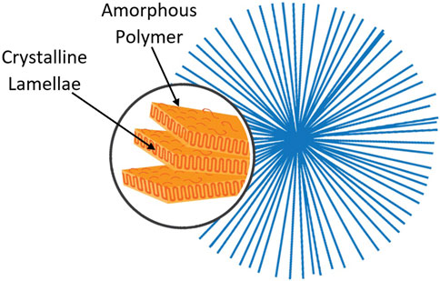
FIGURE 2. Schematic representation of a spherulite (semicrystalline structure).
Spherulites have been widely studied in polymer science, and the relationships of spherulite morphology to mechanical and other properties have been extensively explored. For instance, it was shown in early studies that the number and size of spherulites are directly correlated with the yield point and overall physical behavior of polymers (Starkweather and Brooks, 1959; Pavlov, 1971).
Some efforts to better understand the local mechanical properties have been deployed for mapping along the spherulite radius (Enrique-Jimenez et al., 2016), and to manipulate these structures during the process, with the application of new conditions such as nucleation agents and external loads, obtaining a better orientation of the lamellae and overall elongation (Huan et al., 2013).
Other arrangements are possible to observe when the lamellar crystals grow out from a common row nucleus, resulting in a higher level of anisotropy. Not surprisingly these different types of spatial arrangements exhibit different properties both with regard to mechanical behavior and degradation in the case of biodegradable polymers used in biomedical applications (Shah and Vasava, 2019).
The formation of row nuclei can be associated with the development of extended chain conformations due to strain in a flow system (Phillips, 1990). Equally highly anisotropic nanoparticles, such as carbon nanotubes (Li et al., 2009) or self-assembling fibrillar nanoparticulate nucleating agents (Shazleen et al., 2021), can lead to higher anisotropic arrangements and a higher level of crystallinity. In the melt flow, this happens as a consequence of the common alignment of the nucleation sites, assuming that the common orientation of the particles introduced during the flow persists at the time crystallization is initiated.
The same mechanism can occur with the longest molecular chains in a polymer melt. This flow-induced orientation is often associated with the formation of shish-kebab semicrystalline structures (Keller, 1970; Phillips, 1990) (represented in Figure 3).
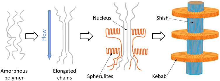
FIGURE 3. Schematic representation of the formation of a shish kebab semicrystalline structure. Adapted from (Dargazany et al., 2014).
Basically, the longest chains (with higher molecular weight) become elongated due to the stresses in the flow. If, when reaching the crystallization temperature, these chains remain elongated, they template the nucleation (acting as row nuclei) for the surrounding polymer melt and chain folded lamellar crystals to grow out from. These lamellar crystals have their growth direction normal to the nuclei formed from the elongated chains (Somani et al., 2005).
In extrusion-based 3D printing, independently of the plastic part design, the polymer in the liquid phase is forced to pass through a restricting die (nozzle) with a certain length-to-diameter ratio (L/D). Even considering that the extrudate swells at the exit of the extruder (Wang and de Vicente, 2012), the resultant strand diameter is mainly defined by the nozzle diameter, and consequently, it defines the printing resolution, as observed in Figure 4.
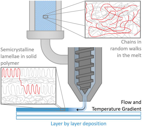
FIGURE 4. Representation of the polymer morphology overall change during FGF 3D printing. The two highlights, from left to right, respectively correspond to the melt in the reservoir and the deposited extrudate along the print.
Shear stresses are applied in order to force the melt to pass through a constricted zone. For semicrystalline polymers (as it is illustrated in Figure 4), this condition induces the elongation of the larger chains (Rubinstein and Colby, 2003), which can generate flow-induced oriented structures such as the shish-kebab arrangements presented in Figure 3. In practice, this results in a higher proportion of crystalline to amorphous material.
These higher levels of preferred molecular alignment are expected to be translated into having a significant impact on the mechanical properties of the manufactured part. As an example, 3D printed objects can be mapped to be much stiffer in the longitudinal axis of the extruded strands, contrasting with a typical isotropic structure regularly obtained.
In this experiment, the samples correspond to the in-situ produced extrudates of semicrystalline thermoplastic. With the 3D printer analogous equipment, the trials were performed with low-density polyethylene (LDPE) from Repsol, the Alcudia® 1970C, with a melt flow index of 7.5 g/10 min.
For the realization of the morphology analysis, the X-ray scattering was performed with synchrotron radiation, similarly to what has been performed by Mitchell, et al. (Pople et al., 1996); utilizing an especially developed apparatus, in this case, to replicate the extrusion-based 3D printer operation at the beamline. The facilities and the equipment are followingly described in Section 2.2.1; Section 2.2.2.
Small and wide-angle X-ray scattering measurements were performed at the ALBA Synchrotron Light Source in Barcelona (Spain), using the NCD-SWEET Beamline (González et al., 2018). This beamline has equipment for the capture of SAXS and WAXS patterns simultaneously. The SAXS patterns were obtained in a Q-range from 0.002 Å−1 to 0.125 Å−1 and the WAXS patterns from 1.0 Å−1 to 3 Å−1. The SAXS Detector is a Pilatus3 S 1M system from DECTRIS, a hybrid single photon counting system. The X-ray photon absorption in the detector leads to the formation of electron-hole pairs and a charge proportional to the photon energy.
The Pilatus system is constituted by an arranged set of silicon sensors, and as a consequence, approximately ∼7% of the detector is intrinsically inactive (this unutilized zone appears as a black stripes grid in the intensity recordings). Regarding the charge, it is detected and processed by the pixel readout system, and the effective pixel has a dynamic range of 20 bits and a size of 172 × 172 μm2. In order to prevent the saturation and damage of the detector, a beam stop is placed in front of the detector to absorb the zero-angle transmitted beam. The sample to SAXS detector distance was 7.27 m with an incident X-ray wavelength of 1 Å. The detector orientation and sample-to-detector distance were calibrated using the well-known standard silver behenate.
The WAXS detector was a Rayonix LX255 HS which is a triple cooled CCD detector bonded to fiber optic tapers to the X-ray photon detector surface, with a pixel size of 44.27 × 44.27 μm2. The geometry of the detector ensures that the direct beam and the SAXS pattern are not blocked by itself. The WAXS orientation and sample to detector distance were calibrated using Cr2O3 For each 2D SAXS pattern an azimuthal section I (α) was obtained at constant |Q| and as a function of α, which is the angle between the extrusion axis (vertical to the beamline) the beamline and the scattering vector Q. The values of I (α) were necessary to evaluate the level of preferred orientation of the chain folded lamellar crystals (given by < P2n > Q), using the methodology developed by Mitchell (Lovell and Mitchell, 1981; Mitchell et al., 2005; Mohan et al., 2016), represented in the equation below.
Where n = 0,2,4,6,8 … Only the even orders are required due to the intrinsic inversion centre present in the diffraction pattern of a weakly absorbing material. The n = 0 is the component which represents the scattering from an equivalent sample without any preferred orientation, n = 2 is the first anisotropic pattern and values of <P2n > correspond to the Herman’s orientation parameter. Typically, in a scattering pattern from a sample with a high level of preferred orientation, the first 11 components, i.e., up to n = 20, are required to fully described the scattering and the orientation distribution function. However, these spherical harmonics are orthogonal functions and a knowledge of one does not depend on the knowledge of the others. For samples with a lower level of preferred orientation only components up to n = 8 will be required.
This equation describes the orientation distribution function of the normal vectors to the lamellar crystals (Q). The first component < P2n> is defined as the orientation parameter, and it reveals, on a scale from 0 to 1 the level of anisotropy of the polymer morphology: if < P2n>=0, then the morphology is isotropic; if < P2n>=1, then the crystals share the same alignment.
One of the challenges of performing 3D printing trials at the ALBA synchrotron NCD-SWEET beamline consisted of the process and equipment adaptation. For the experiment with low-density polyethylene extrusion, the team of the present work resorted to the apparatus described in da Silva et al. (2022). It consists of a device that can be mounted on the standard sample platform, and it was designed to allow a continuous and stable extrusion, aligning the extrudate sample with the X-ray beam. The model of the printer and the schematic of the experiment are presented in Figure 5.
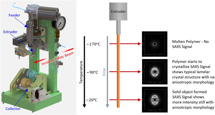
FIGURE 5. (Left) A CAD representation of the 3D printer developed for this work. (Right) A schematic of the quasi-static state of the extrudate in a constant gradient of temperature (from the extrusion of the LDPE, passing through crystallization, until cooling down to the surrounding temperature). The evolution of structure can be evaluated by moving the incident X-ray beam down the jet. Adapted from da Silva et al. (2023).
Comprising three main parts (feeder, extruder, and rotating collector), this equipment simulates extrusion-based 3D printing along a moving platform, with a theoretically infinite path in a single deposition direction (for a wider testing window).
This system is adjustable in the cartesian axis and uses a single extruder with a dual channel screw to push the polymer melt through a needle with a high length-to-diameter ratio (L/D ≈ 36).
The FGF extruder utilized has a similar design to the one used in the bioextruder (Almeida et al., 2010) (also developed by a team of CDRSP-Polytechnic of Leiria), and it corresponds to the configuration c) in Figure 1. Thus, it contains an attached material reservoir and three independent zones of temperature control.
The communication with a microcontroller board enables the remote operation of the apparatus, more specifically the control of the collector velocity (write/print speed), extruder screw rotation velocity (extrusion rate), and the nozzle wiping mechanism.
Figure 6 is a representation of the experimental assembly with the 3D printer mounted on the beamline platform, together with the SAXS and WAXS detectors to the scales of observation: lamellae morphology (∼100 Å) and crystalline structures (∼10 Å), respectively.
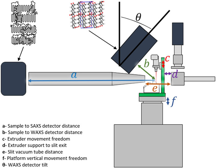
FIGURE 6. Representation of the 3D printer analogous equipment mounted on the NCD-SWEET beamline at the ALBA Synchrotron Light Source, with the domain of pattern observation of each detector. Adapted from da Silva et al. (2022).
Besides the schematic of the small and wide-angle detectors arrangement, this representation shows the main dimensions related to the beamline facilities and the 3D printer. For the vertical adjustment of the area to be scanned, the distance between the needle outlet and the collector is variable by 50 mm. The distance from the sample to the SAXS detector (given by a) was 7.274 m.
The temperature profile of the extruded filament was maintained constant. Hence, it was possible to observe the extrudate in a quasi-steady state, in which the evolution of the structure and morphology with time could be assessed by moving up and down the platform; repositioning the incident X-ray beam along the extruded filament. Remotely and automatically controlled, a scan of 20 steps of 0.1 mm with a 1-s data collection period could be obtained, for each trial. A photograph of the equipment on the beamline is followingly presented in Figure 7.
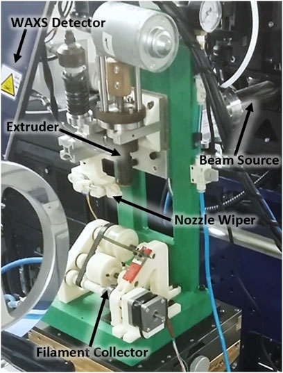
FIGURE 7. Photograph of the equipment on the mounting stage of the beamline.
The evaluation of the LDPE crystallization was performed using differential scanning calorimetry (DSC) with a PerkinElmer STA 6000 thermal analyzer. Samples were heated from 30°C to 150°C at a rate of 10°C/min. A steady state at the maximum temperature was maintained for 5 min, followed by cooling back to 30°C at a rate of 5°C/min. The final cooling stage is represented in Figure 8.
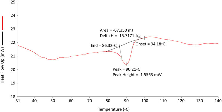
FIGURE 8. DSC cooling scan of a sample of LDPE used in this work from 150°C to room temperature (around 30°C) showing the crystallization peak which reveals the maximum rate for a quiescent melt at 90.2°C.
In this domain of the DSC cooling scan, it is observed that in the quiescent material, the onset of crystallization occurs at 94.2°C while the maximum rate of crystallization is observed to be at a temperature of 90.2°C. Notice that the material which has been extruded may start to crystallize at a higher temperature than the observed with the quiescent material, due to the presence of flow-induced row nuclei.
In this section, the results of the in-situ small and wide X-ray scattering analysis are presented. Figures 9A–C shows the recorded SAXS scattering patterns of the filaments extruded with different write speeds (print speeds), maintaining the extrusion temperature and rate.
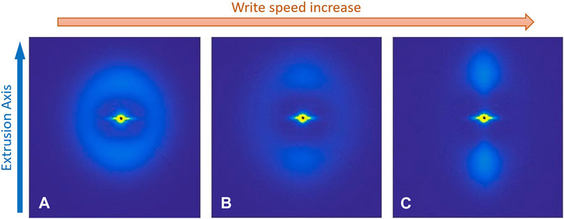
FIGURE 9. SAXS patterns from the last point of each scan down the extruded filament, at a temperature of 170°C, and a constant extrusion rate with different write/print speeds [increasing from (A–C)]. Adapted from da Silva et al. (2023).
These SAXS patterns correspond to the point just before the build platform and are typical for a semicrystalline polymer. Figure 9A shows a practically isotropic ring, indicating an isotropic distribution of the lamellar crystals. On the other hand, Figure 9C exhibits a highly anisotropic distribution of scattering suggesting a higher degree of order of lamellar crystals. Figure 9B corresponds to an intermediate write speed, and it comprises both isotropic and highly anisotropic scatterings.
The WAXS pattern presented in Figure 10 was recorded in the same instant as Figure 9C SAXS pattern. It shows the intense peaks for LDPE, the 110 and 200, corresponding to the arcs observed from right to left. Moreover, the development of an anisotropic morphology is indicated by the variation of the peaks’ intensity in the azimuthal range.
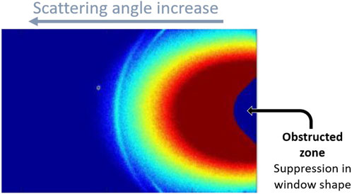
FIGURE 10. WAXS pattern recorded at the same time as the SAXS pattern shown in Figure 9C. The scattering angle increases from left to right. Only the lower half of the angular range is shown in this figure, corresponding to a Q range of 1 to 2 Å−1. Adapted from da Silva et al. (2023).
It is noticed that the anisotropy revealed in the WAXS pattern is less pronounced than the one observed with SAXS. This observation underlines the challenge of using wide-angle X-ray scattering to assess the orientation of structures in semicrystalline polymers. In the case of LDPE, the twisted arrangement of chain-folded lamellar crystals is commonly observed. Thus, the preferred orientation of the lamellar crystals cannot be evaluated simply from WAXS patterns.
The preferred level of orientation of the lamellar crystals, the results are shown in Figure 11. The vertical axis corresponds to the orientation parameter < P2n>, obtained through Eq. 1. Once again, this parameter can assume values from 0 to 1, respectively corresponding to a scale from completely isotropic to anisotropic morphology (uniform orientation of the crystalline structures).
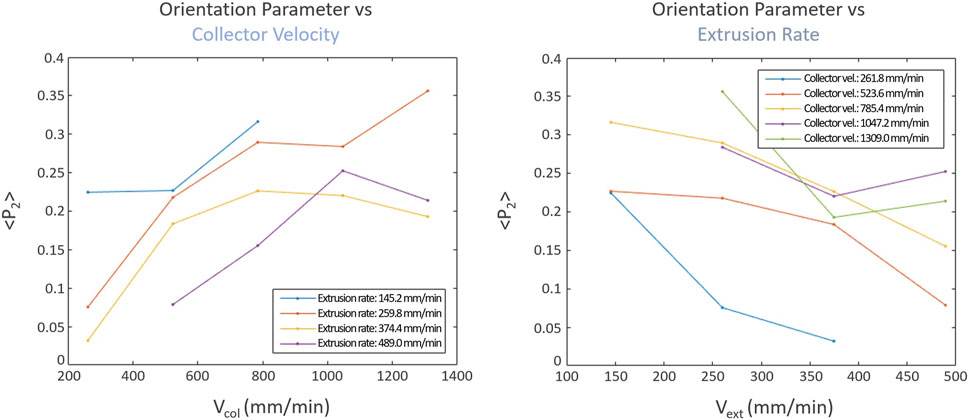
FIGURE 11. Plots of the level of preferred orientation of the chain folded lamellar crystals in extruded strands of low-density polyethylene (LDPE) as a function of the collector velocity/print speed (on the left) and the extrusion velocity (on the right), at a constant extrusion temperature.
For the elaboration of both graphs, the temperatures of the 3 main zones of the extruder (feeder, channel, and extruder body) remained constant (extrusion temperature of 190°C). The left-hand plot corresponds to the variation of the preferred orientation level with the collector velocity (maintaining the extrusion rate value). The plot at the right corresponds to the variation of <P2n> with the extrusion rate (at constant values of collector velocity). Notice that printing speed is represented by the collector main roll rotation velocity given by the product of its angular velocity and radius.
In order to display any correlations between the preferred molecular orientation and extrusion and collector velocities, the three-dimensional plot shown Figure 12 was prepared, with the combined data from both plots in Figure 11.
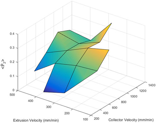
FIGURE 12. Three-dimensional plot of the level of preferred orientation of the normals to the chain folded lamellar crystals in extruded strands of low-density polyethylene (LDPE) as a function of the extrusion velocity and the write speed (collector velocity) at a constant extrusion temperature, obtained using the data in Figure 11. Adapted from da Silva et al. (2023).
Clearly, from the obtained results, it is possible to observe the final anisotropy level in LDPE, establishing a briefer correlation with both the extrusion and writing/print speeds (this one represented by the collector velocity), with the help of a color scale. The dark blue corresponds to the isotropic zone, and the yellow zones correspond to the higher anisotropy levels.
In summary, and in a broad observation, the level of preferred orientation of the chain folded lamellar crystals is directly proportional to the collector velocity (write/print speed) and inversely proportional to the extrusion rate.
In practice, during manufacturing, this is represented by a more pronounced anisotropy value (associated with higher elastic modulus) (da Silva et al., 2022) is reached while extruding a smaller amount of material along the same or a bigger path. This can be translated as a thinning of the deposited filament, and a faster cooling rate.
Particular attention has to be given to the faster cooling rates and the thinning of the extrudate, once it may compromise, in a counter-productive way, the interlayer adhesion, as well as the adhesion between subsequently deposited filaments. Consequently, it may affect the mechanical properties and behavior of the generated part (Geng et al., 2019).
This condition has to be considered in advance, during the part design. Usually, slicing software provides these correlations in order to accomplish the intended geometries. However, if the design for additive manufacturing strategy incorporates this thinning, another solution should be the revision of the number of cycles/scans to fulfill a given length/width. Given the circumstances, it is not clearly proven that faster deposition movements of the extrudate should consist of accelerated production. Therefore, we can-not conclude, at some other level of process optimization, and with the actual data, if the achievement of a higher level of anisotropy in semicrystalline polymers can be promptly or fully associated with more agile production cycles. The use of higher extrusion speed doesn’t necessarily imply a higher manufacturing pace and may limit the overall rate of production.
Perhaps, new slicing strategies could be applied in order to optimize the anisotropy and, consequently, obtain well-defined stiffer and softer zones, while maintaining a relatively normal to fast-paced production.
The main conclusion of the present work is that the adjustment of 3D printing parameters (nozzle temperature, extrusion rate and write speed) can be utilized strategically to affect the material morphology and structure along the fabrication of an object. Exploring the levels of preferred orientation of the lamellar crystals, it is possible to transcribe expected properties, correlated with the balance between isotropic and anisotropic distributions.
As an example, higher write speeds lead to faster cooling. For the same given temperature differential (from the nozzle to the cooled state of the deposited material), as the print speed increases, the extended chains, constrained and reoriented in the melt flow, don’t have enough time to relax and remain mostly extended during crystallization, generating highly-aligned, therefore anisotropic morphology.
With a single material, the conception phase of a product can employ this morphology mapping strategy in order to set different mechanical properties. In the future, it should be expected the possibility to alter conditions and process parameters “on demand”, during fabrication, to obtain desirable properties in particular zones of a single material manufactured part. This work is dedicated to promoting that approach, instead of considering, as in the current paradigm, that the predetermined set of values should be maintained during the whole 3D printing production.
Certainly, and depending on the parameter to change (monitoring and control main variable), its set value is theoretically met within a certain period. How short or long that response turns out to be, in conjunction with the required time for those changes to have an effect on the material morphology, determines the resolution of the mapping.
Summarizing, controlling the core parameters of 3D printing induces changes in the material structure and morphology of semicrystalline polymers like LDPE. As a consequence, it is predicted that will affect the functionality of the printed part, allowing the enhancement of mechanical properties in a localized way. Therefore, more than reproducing a certain desired shape, it is believed that 3D printing may help develop new degrees of function for even more complex parts.
The results obtained in this work will be typical for all semicrystalline polymers, but the particular details of the correlations will depend on the polymer type, the molecular weight and characteristics of the 3D printing systems used, including the temperature of the extrusion and the L/D ratio of the extrusion die.
As this project is progressing, future works include studies about the rheological behavior, mechanical testing, 3D printing trials, the development of new products, and the influence of other variables such as the extrudate temperature. In the future, the main challenge will consist of the implementation of the correlated data into a manufacturing system where the properties of the materials will be locally assigned along with the digital definition of the objects to produce. Additionally, the active control of the manufacturing process, envisioning the optimization of the parts will depend on the implementation of new strategies of slicing, and the development of software to run the 3D printing process in accordance with the material design strategies.
The datasets presented in this study can be found in online repositories. The names of the repository/repositories and accession number(s) can be found below: https://www.cells.es/en/users/call-information-1/bases/2017_07_data_policy_alba_approved-cr.pdf.
Conceptualization, GM, DS, and JP; methodology, DS, CK-L, JM, ES, and GM; software, GM and JP; validation, GM and JP; formal analysis, JP; investigation, JP, DS, SA, and PP-F.; resources, GM; data curation, DS; writing—original draft preparation, DS and GM; writing, DS, JP, GM, and PP-F; visualization, JP and GM; supervision, GM, AM, and PF-F; project administration, GM and PP-F; funding acquisition, GM, PP-F, and AM. All authors contributed to the article and approved the submitted version.
This work is supported by the Fundação para a Ciência e Tecnologia (FCT) through the Project references: MIT-EXPL/TDI/0044/2021, UID/Multi/04044/2013; PAMI-Roteiro/0328/2013 (No. 022158), Add.Additive—Add additive manufacturing to Portuguese industry PO-CI-01-0247-FEDER-024533 and UC4EP PTDC/CTM-POL/7133/2014).
These experiments were performed at NCD-SWEET beamline at ALBA Synchrotron with the collaboration of ALBA staff. We thank Miguel Belbut from CDRSP-IPLeiria for his help with the evaluation of the orientation parameter.
The authors declare that the research was conducted in the absence of any commercial or financial relationships that could be construed as a potential conflict of interest.
All claims expressed in this article are solely those of the authors and do not necessarily represent those of their affiliated organizations, or those of the publisher, the editors and the reviewers. Any product that may be evaluated in this article, or claim that may be made by its manufacturer, is not guaranteed or endorsed by the publisher.
Achilias, D. S., Roupakias, C., Megalokonomos, P., Lappas, A. A., and Antonakou, V. (2007). Chemical recycling of plastic wastes made from polyethylene (LDPE and HDPE) and polypropylene (PP). J. Hazard Mater 149, 536–542. doi:10.1016/j.jhazmat.2007.06.076
Almeida, H. A., Bártolo, P. J., and Mota, C. M. (2010). Processo e Equipamento de Fabrico Rápido Por Bioextrusão 2010.
Bassett, D. C. (1986). “Lamellar organization in polymer spherulites,” in Integration of fundamental polymer science and technology. Editors L. A. Kleintjens, and P. J. Lemstra (Dordrecht: Springer Netherlands), 466–470. ISBN 978-94-009-4185-4.
Bedi, P., Singh, R., and Ahuja, I. P. S. (2018). Effect of SiC/Al2O3 particle size reinforcement in recycled LDPE matrix on mechanical properties of FDM feed stock filament. Virtual Phys. Prototyp. 13, 246–254. doi:10.1080/17452759.2018.1496605
Chatkunakasem, P., Luangjuntawong, P., Pongwisuthiruchte, A., Aumnate, C., and Potiyaraj, P. (2018). Tuning of HDPE properties for 3D printing. Key Eng. Mater 773, 67–71. doi:10.4028/www.scientific.net/kem.773.67
Chen, D., Heyer, S., Ibbotson, S., Salonitis, K., Steingrímsson, J. G., and Thiede, S. (2015). Direct digital manufacturing: Definition, evolution, and sustainability implications. J. Clean. Prod. 107, 615–625. doi:10.1016/j.jclepro.2015.05.009
Cruz Sanchez, F. A., Boudaoud, H., Hoppe, S., and Camargo, M. (2017). Polymer recycling in an open-source additive manufacturing context: Mechanical issues. Addit. Manuf. 17, 87–105. doi:10.1016/j.addma.2017.05.013
da Silva, D. P., Holt, J. J., Pratumshat, S., Pascoal-Faria, P., Mateus, A., and Mitchell, G. R. (2023). “Crystallization from anisotropic polymer melts,” Polymer crystallization. Editors J. Parameswaranpillai, J. Jacob, S. Krishnasamy, A. Jayakumar, and N. Hameed doi:10.1002/9783527839247.ch10
da Silva, D. P., Pinheiro, J., Abdulghani, S., Lorger, C. K., Martinez, J. C., Solano, E., et al. (2022). Changing the paradigm-controlling polymer morphology during 3D printing defines properties. MDPI Polym. 14, 1638–1714. doi:10.3390/polym14091638
Dargazany, R., Khiêm, V. N., Poshtan, E. A., and Itskov, M. (2014). Constitutive modeling of strain-induced crystallization in filled rubbers. Phys. Rev. E Stat. Nonlin Soft Matter Phys. 89, 022604. doi:10.1103/PhysRevE.89.022604
Duan, M., Yoon, D., and Okwudire, C. E. (2018). A limited-preview filtered B-spline approach to tracking control – with application to vibration-induced error compensation of a 3D printer. Mechatronics 56, 287–296. doi:10.1016/j.mechatronics.2017.09.002
Durakovic, B. (2018). Design for additive manufacturing: Benefits, trends and challenges. Periodicals Eng. Nat. Sci. 6, 179–191. doi:10.21533/pen.v6i2.224
Enrique-Jimenez, P., Vega, J. F., Martínez-Salazar, J., Ania, F., and Flores, A. (2016). Mapping the mechanical properties of poly(3-hydroxybutyrate-Co-3-Hydroxyvalerate) banded spherulites by nanoindentation. MDPI Polym. 8, 358. doi:10.3390/polym8100358
Enkelmann, V. (1984). “Structural aspects of the topochemical polymerization of diacetylenes,” in Polydiacetylenes. Advances in polymer science (Berlin, Heidelberg: Springer), 91–136. doi:10.1007/bfb0017652
Ezquerra, T. A., Nogales, A., García-Gutiérrez, M. C., Rebollar, E., Gálvez, O., Šics, I., et al. (2022). Probing structure development in poly(vinylidene fluoride) during “operando” 3-D printing by small and wide angle X-ray scattering. Polym. Guildf. 249, 124827. doi:10.1016/j.polymer.2022.124827
Fico, D., Rizzo, D., Casciaro, R., and Corcione, C. E. (2022). A review of polymer-based materials for fused filament fabrication (FFF): Focus on sustainability and recycled materials. Polym. (Basel) 14, 465–535. doi:10.3390/polym14030465
Geng, P., Zhao, J., Wu, W., Ye, W., Wang, Y., Wang, S., et al. (2019). Effects of extrusion speed and printing speed on the 3D printing stability of extruded PEEK filament. J. Manuf. Process 37, 266–273. doi:10.1016/j.jmapro.2018.11.023
Geyer, R., Jambeck, J. R., and Law, K. L. (2017). Production, use, and fate of all plastics ever made. Sci. Adv. 3, e1700782–e1700788. doi:10.1126/sciadv.1700782
Gibson, I., Rosen, D., and Brent, S. (2015). Additive manufacturing technologies, 3D printing, rapid prototyping, and direct digital manufacturing. ISBN 978-1-4939-2113-3.
González, J. B., González, N., Colldelram, C., Ribó, L., Fontserè, A., Jover -Manas, G., et al. (2018). “NCD-SWEET beamline upgrade,” in Proceedings of the MEDSI2018 proceedings of the 10th mechanical engineering design of synchrotron radiation equipment and instrumentation paris (Paris: France).
Huan, Q., Zhu, S., Ma, Y., Zhang, J., Zhang, S., Feng, X., et al. (2013). Markedly improving mechanical properties for isotactic polypropylene with large-size spherulites by pressure-induced flow processing. Polym. Guildf. 54, 1177–1183. doi:10.1016/j.polymer.2012.12.055
Johansen, M. R., Christensen, T. B., Ramos, T. M., and Syberg, K. (2022). A review of the plastic value chain from a circular economy perspective. J. Environ. Manage 302, 113975. doi:10.1016/j.jenvman.2021.113975
Keller, A. A. (1957). A note on single crystals in polymers: Evidence for a folded chain configuration. Philosophical Mag. A J. Theor. Exp. Appl. Phys. 2, 1171–1175. doi:10.1080/14786435708242746
Kristiawan, R. B., Imaduddin, F., Ariawan, D., Ubaidillah, , and Arifin, Z. (2021). A review on the fused deposition modeling (FDM) 3D printing: Filament processing, materials, and printing parameters. Mater. Print. Param. 11, 639–649. doi:10.1515/eng-2021-0063
Li, L., Li, B., Hood, M. A., and Li, C. Y. (2009). Carbon nanotube induced polymer crystallization: The formation of nanohybrid shish-kebabs. Polym. Guildf. 50, 953–965. doi:10.1016/j.polymer.2008.12.031
Lovell, R., and Mitchell, G. R. (1981). Molecular orientation distribution derived from an arbitrary reflection. Acta Crystallogr. Sect. A 37, 135–137. doi:10.1107/s0567739481000247
Mikula, K., Skrzypczak, D., Izydorczyk, G., Warchoł, J., Moustakas, K., Chojnacka, K., et al. (2021). 3D printing filament as a second life of waste plastics—A review. Environ. Sci. Pollut. Res. 28, 12321–12333. doi:10.1007/s11356-020-10657-8
Mitchell, G. R., Saengsuwan, S., and Bualek-Limcharoen, S. (2005). Evaluation of preferred orientation in multi-component polymer systems using x-ray scattering procedures. Prog. Colloid Polym. Sci. 130, 149–158. doi:10.1007/b107341
Mohan, S. D., Olley, R. H., Vaughan, A. S., and Mitchell, G. R. (2016). in Controlling the morphology of polymers: Multiple scales of structure and processing. Editors G. R. Mitchell, and A. Tojeira (Berlin, Germany: Springer). ISBN 978-3-319-39320-9.
Morouço, P., Biscaia, S., Moura, C., and Alves, N. M. (2015). Biomedical applications from a direct digital manufacturing perspective. Material Sci. Eng. Adv. Res. 1, 15–17. doi:10.24218/msear.2015.13
Nogales, A., Gutiérrez-Fernández, E., García-Gutiérrez, M.-C., Ezquerra, T. A., Rebollar, E., Šics, I., et al. (2019). Structure development in polymers during fused filament fabrication (FFF): An in situ small- and wide-angle X-ray scattering study using synchrotron radiation. Macromolecules 52, 9715–9723. doi:10.1021/acs.macromol.9b01620
Olesik, P., Godzierz, M., and Kozioł, M. (2019). Preliminary characterization of novel LDPE-based wear-resistant composite suitable for FDM 3D printing. Materials 12, 2520. doi:10.3390/ma12162520
Pantyukhov, P., Kolesnikova, N., and Popov, A. (2016). Preparation, structure, and properties of biocomposites based on low-density polyethylene and lignocellulosic fillers. Polym. Compos 37, 1461–1472. doi:10.1002/pc.23315
Paritala, P. K., Manchikatla, S., and Yarlagadda, P. K. D. (2017). Digital manufacturing- applications past, current, and future trends. Procedia Eng. 174, 982–991. doi:10.1016/j.proeng.2017.01.250
Pavlov, V. I. (1971). Investigation of the effect of spherulite size on the strength and deformation characteristics of isotactic polypropylene films. Soviet Mater. Sci. 4, 438–440. doi:10.1007/BF00721450
Phillips, P. J. (1990). Polymer crystals. Rep. Prog. Phys. 53, 549–604. doi:10.1088/0034-4885/53/5/002
Pople, J. A., Mitchell, G. R., and Chai, C. K. (1996). In-situ time-resolving wide-angle X-ray scattering study of crystallization from sheared polyethylene melts. Polym. Guildf. 37, 4187–4191. doi:10.1016/0032-3861(96)00264-9
Rubinstein, M., and Colby, R. (2003). Polymer physics. Oxford: Oxford University Press. ISBN 019852059X.
Shah, T. v., and Vasava, D. v. (2019). A glimpse of biodegradable polymers and their biomedical applications. E-Polymers 19, 385–410. doi:10.1515/epoly-2019-0041
Shaik, Y. P., Schuster, J., and Shaik, A. (2021). A scientific review on various pellet extruders used in 3D printing FDM processes. OAlib 08, 1–19. doi:10.4236/oalib.1107698
Shazleen, S. S., Yasim-Anuar, T. A. T., Ibrahim, N. A., Hassan, M. A., and Ariffin, H. (2021). Functionality of cellulose nanofiber as bio-based nucleating agent and nano-reinforcement material to enhance crystallization and mechanical properties of polylactic acid nanocomposite. MDPI Polym. 13, 389–419. doi:10.3390/polym13030389
Shmueli, Y., Jiang, J., Zhou, Y., Xue, Y., Chang, C.-C., Yuan, G., et al. (2019). Simultaneous in situ X-ray scattering and infrared imaging of polymer extrusion in additive manufacturing. ACS Appl. Polym. Mater 1, 1559–1567. doi:10.1021/acsapm.9b00328
Silva, D., Abdulghani, S., Kamma-lorger, C. S., Solano, E., Martinez, J. C., Pascoal-faria, P., et al. (2022). Controlling morphological development during additive manufacturing: A route to the mapping of properties †. Mater. Proc. 8, 116. doi:10.3390/materproc2022008116
Singh, R., Kumar, S., Singh, A. P., and Wei, Y. (2022). On comparison of recycled LDPE and LDPE–bakelite composite based 3D printed patch antenna. Proc. Institution Mech. Eng. Part L J. Mater. Des. Appl. 236, 842–856. doi:10.1177/14644207211060465
Somani, R. H., Yang, L., Zhu, L., and Hsiao, B. S. (2005). Flow-induced shish-kebab precursor structures in entangled polymer melts. Polym. Guildf. 46, 8587–8623. doi:10.1016/j.polymer.2005.06.034
Stanciu, N., Stan, F., Fetecau, C., and Serban, A. (2018). Fabrication and characterization of LDPE and HDPE filaments for 3D printing. J. Eng. Sci. Innovation 3, 299–312. doi:10.56958/jesi.2018.3.4.299
Starkweather, H. W., and Brooks, R. E. (1959). Effect of spherulites on the mechanical properties of nylon 66. J. Appl. Polym. Sci. 1, 236–239. doi:10.1002/app.1959.070010214
Turner, B. N., and Gold, S. A. (2015). A review of melt extrusion additive manufacturing processes: II. Materials, dimensional accuracy, and surface roughness. Rapid Prototyp. J. 21, 250–261. doi:10.1108/RPJ-02-2013-0017
Verma, N., Awasthi, P., Gupta, A., and Banerjee, S. S. (2023). Fused deposition modeling of polyolefins: Challenges and opportunities. Macromol. Mater Eng. 2023, 308. doi:10.1002/mame.202200421
Volpato, N., Kretschek, D., Foggiatto, J. A., and Gomez da Silva Cruz, C. M. (2015). Experimental analysis of an extrusion system for additive manufacturing based on polymer pellets. Int. J. Adv. Manuf. Technol. 81, 1519–1531. doi:10.1007/s00170-015-7300-2
Wang, K. (2012). “Die swell of complex polymeric systems,” in Viscoelasticity - from theory to biological applications. Editor J. de Vicente (London, UK: IntechOpen), 77–96. ISBN 978-953-51-0841-2.
Whyman, S., Arif, K. M., and Potgieter, J. (2018). Design and development of an extrusion system for 3D printing biopolymer pellets. Int. J. Adv. Manuf. Technol. 96, 3417–3428. doi:10.1007/s00170-018-1843-y
Keywords: direct digital manufacturing, 3D printing, extrusion, fused granular fabrication, LDPE, polymer morphology, crystallization, SAXS/WAXS
Citation: da Silva DP, Pinheiro J, Abdulghani S, Kamma-Lorger C, Martínez JC, Solano E, Mateus A, Pascoal-Faria P and Mitchell GR (2023) Property mapping of LDPE during 3D printing: evaluating morphological development with X-ray scattering. Front. Mech. Eng 9:1232562. doi: 10.3389/fmech.2023.1232562
Received: 31 May 2023; Accepted: 24 July 2023;
Published: 08 August 2023.
Edited by:
Asif Ur Rehman, ERMAKSAN, TürkiyeReviewed by:
Zulfiqar Ali, The University of Hong Kong, Hong Kong SAR, ChinaCopyright © 2023 da Silva, Pinheiro, Abdulghani, Kamma-Lorger, Martínez, Solano, Mateus, Pascoal-Faria and Mitchell. This is an open-access article distributed under the terms of the Creative Commons Attribution License (CC BY). The use, distribution or reproduction in other forums is permitted, provided the original author(s) and the copyright owner(s) are credited and that the original publication in this journal is cited, in accordance with accepted academic practice. No use, distribution or reproduction is permitted which does not comply with these terms.
*Correspondence: Geoffrey R. Mitchell, Z2VvZmZyZXkubWl0Y2hlbGxAaXBsZWlyaWEucHQ=
Disclaimer: All claims expressed in this article are solely those of the authors and do not necessarily represent those of their affiliated organizations, or those of the publisher, the editors and the reviewers. Any product that may be evaluated in this article or claim that may be made by its manufacturer is not guaranteed or endorsed by the publisher.
Research integrity at Frontiers
Learn more about the work of our research integrity team to safeguard the quality of each article we publish.