 Osama Haggag
 Mehmet Hakan Demir
 Sabri Cetin1
 William Worek
- 1Department of Mechanical and Industrial Engineering, University of Illinois at Chicago, Chicago, IL, United States
- 2Argonne National Laboratory, Lemont, IL, United States
- 3Baryon Inc, Wilmington, DE, United States
- 4Department of Mechanical and Power Engineering, Wroclaw University of Science and Technology, Wroclaw, Poland
Increasing the energy efficiency of cooling in buildings is an important component of the management of global energy consumption. A super-efficient cooling system based on the evaporation concept has been developed, and initial simulation results using the MATLAB/Simulink software tool have already been published by our team. In this paper, we present the results of hardware-in-the-loop (HIL) testing of the real-time controller for the cooler. HIL testing is an engineering process in which the actual controller hardware and software are implemented and interfaced with a real-time simulated model of the controlled system. Using HIL testing, many real-world problems can be fixed before testing on the actual prototype. The controller design is implemented on a small-footprint industrial PC with CODESYS RTE and application code, while control software is implemented using IEC 61131-3 programming languages. Similarly, a real-time thermodynamic and input–output variable-based model of the room, environment, and cooler and its mechanical components (sensors and actuators) are modeled using another industrial PC with the same software tools. HIL test results show very good agreement with the offline simulations.
1 Introduction
Due to the increase in the population and the technological achievements in recent years causing the increase in device usage, the topic of energy savings has been at the forefront of discussion. A large portion of energy used all over the world is attributed to buildings for the purpose of cooling (35% of building energy) (International Energy Agency Report, 2021). Therefore, finding ways to reduce the energy consumed by buildings is very important for energy efficiency and resulting environmental protection (Asim et al., 2019; Zhang et al., 2022). There are multiple ways and methods to achieve this goal. An example would be to use desiccant cooling methods along with evaporative coolers (ECs). A desiccant cooling system is a heat-operated cooling unit. This cooling system functions on the operation of the desiccant wheel dehumidifier that dehumidifies the air inside the cooler; when combined with ECs and their efficient performance, it is possible to increase efficiency even further in humid climates (Dincer and Rosen, 2007; Pandelidis et al., 2017; Pacak and Worek, 2021). The performance of the desiccant evaporative cooling system is investigated in many studies in the literature. Narayanan et al. (2018) studied the solid desiccant EC for humid and warm climates. The performance of this cooler was investigated for residential applications in Brisbane, Queensland, Australia, and the findings revealed that the humidity level of the place is one of the most critical factors, which has a significant effect on the system performance. Caliskan et al. (2020) investigated the effects of regenerative ECs on the dry desiccant cooling system. The results showed that the energy efficiency of the cooler changed depending on the modification of the cooler and the effectiveness of the cooler increased from 0.95 to 2.16, while the exergy efficiency increased up to 42%. Pandelidis et al. (2016) investigated the effects of the different indirect ECs on the cooling performance of the desiccant wheel cooling system. The cross-flow Maisotsenko cycle heat and mass exchanger (HMX), the regenerative counter-flow Maisotsenko cycle heat and mass exchanger, and the standard cross-flow evaporative air cooler were considered to analyze the system performance using the NTU model. The systems showed different sensitivities to different operational factors. The system with the regenerative counter-flow Maisotsenko cycle heat and mass exchanger showed very sensitive performance depending on intake air flow, while the system with the cross-flow Maisotsenko cycle HMX is very sensitive to ambient humidity, and the system with the traditional cross-flow EC is very sensitive to latent heat load in the cooling space. In the other work, Gao et al. (2015) developed a simplified desiccant wheel, and the indirect parameters of the system were optimized for determining the optimal operation points for different outdoor conditions. The results show that increasing NTUHE (number of transfer units of heat exchanger) or NTUIEC (number of transfer units of indirect EC) can both improve the coefficient of performance (COP) of the system. Similarly, Goldsworthy and White (2011) analyzed the performance of the system, which involves the solid desiccant wheel system and indirect EC. Following the heat and mass transfer modeling of all components of the system, attempts were made to identify the optimized parameters that would yield the best performance. The results indicated that a 0.67 supply/regeneration flow ratio for the desiccant wheel and a 0.3 flow ratio for indirect EC gave the COP of the system higher than 20 for 70 regeneration temperature ambient conditions. Moreover, Peng et al. (2017) studied the modeling of the liquid desiccant wheel EC and investigated the effects of the system parameters (hot water temperature, air flow ratio, etc.) on the thermodynamic performance of the system. In addition, the optimal range of these system parameters was determined. The simulations on the model showed that increasing the hot water temperature, mass flow of hot water, and ambient air relative humidity led to an increase in the efficiency of the system.
While the cooling systems are operating, it is necessary to provide the desired conditions in the cooled environment and to consume energy at a minimum while this is provided. Keeping the ambient conditions at reference values is important for minimizing the effects of external and internal disturbing effects, uncertainties, and unknowns while increasing the comfort in the environment to be cooled. Thus, the operation of the system against these changes is regulated, and its robustness is increased. When the studies in the literature are examined, the most effective method for this is the application of a controller that will regulate the operation of the cooling system. With the designed control strategy, ambient conditions are kept at desired values, and maximum energy savings are achieved in the system by adjusting the operating times and internal parameters (fan and wheel speeds) of the cooler. As for the control of cooling systems, many studies that investigate the control of conventional cooling systems (Huang and Lam, 1997; Qi and Deng, 2009; Blasco et al., 2012; Li et al., 2015). Li et al. (2015) designed an artificial neural network (ANN)-based fuzzy logic controller (FLC) for controlling the temperature and humidity in a cooling space with a variable-speed direct expansion air conditioning system. The disturbance effects, such as the variations in air dry bulb and wet bulb temperature, on the system performance were investigated experimentally, and the designed controller showed very successful performance to minimize or eliminate these disturbance effects on the performance. Qi and Deng (2009) developed multi-input and multi-output control techniques for direct expansion air conditioning systems. This linear, quadratic Gaussian-based strategy controlled the indoor air temperature and humidity simultaneously by adjusting the speeds of the compressor and air supply fan. The results showed that the controller adjusts the speeds of the actuators effectively under disturbances such as unmeasured heat load disturbances and other system parameters. Huang and Lam (1997) presented an adaptive PID controller to determine the optimal performance for the heating, ventilating, and air conditioning (HVAC) system. The parameters of the adaptive PID controller were adjusted by a genetic algorithm (GA), and an attempt was made to increase the robustness of the system using this controller. The results show that the GA-based PID controller has successful performance for HVAC systems by minimizing overshoot and settling time by tuning the PID controller’s parameters according to system conditions. Blasco et al. (2012) modeled the HVAC system and designed a PID controller for improving the energy efficiency of the HVAC system under different conditions. The HVAC control system has manual and automatic modes, and it adjusts the electro valves inside the building by using an ON/OFF control strategy to maintain comfort and minimize consumption. These studies, in which the control of temperature and relative humidity was focused on the building and environment, show that energy saving is also very important for these systems in addition to temperature and humidity control. Because the systems provide comfort in the room by performing the cooling process, they need to do this with minimum energy consumption, both in terms of costs and protection of the environment. When looking at these few studies, the best energy-saving method for dew-point evaporative cooler (DPEC) systems is the control of the speed of the actuators. In addition to the aforementioned studies, there are a few studies on the control and energy efficiency of evaporative systems. This speed control to be applied to the actuators is generally applied in two types in the literature. The first of these is ON/OFF control, which is based on the fact that the actuators stop completely at certain time intervals and operate at a determined speed at certain time intervals. The second type of control operates the actuators at variable speeds with the control inputs sent to the actuators according to the ambient conditions. The second type of technique requires the development of application-specific control strategies, but it has been confirmed by studies in the literature that it saves more energy than conventional ON/OFF control. Yan et al. (2017) studied a multi-evaporator air-conditioning (MEAC) system, and a capacity controller and improved capacity were designed to control the temperature and humidity of the indoor area. The results show that the capacity controller directly controls the temperature within their preset dead-bands in the three ECs. However, the improved controller was capable of simultaneously controlling both temperature and humidity. Both controllers improve the energy efficiency of the cooling system. Lin and Yeh (2009) developed a controller for the MEAC system, and a linear model of the system was obtained by using experimental data. The control strategy is based on the principle that the compressor regulates the evaporator temperatures, and expansion valves are adjusted in cases of overheating. Experimental results show that the designed controller can successfully regulate indoor temperatures despite changing environmental and system conditions. Chen et al. (2019) designed a proportional-integral (PI) controller for an indirect EC to control the temperature accurately. The PI-based variable technique was used for more accurate control with more energy saving. The performances of the PI controller and traditional controller were compared, and the results show that the PI controller has a faster response speed, a smaller overshoot, higher precision, and enhanced robustness compared to the traditional controller. Under the control of the PI controller, the fans consumed 50% less energy than the ON/OFF controller. Similarly, Chen et al. (2019) developed a novel high–low controller for regenerative indirect EC, and the performance of this controller was investigated under different conditions. In this control strategy, fans can work at high and low speeds rather than completely on or off depending on the reference and actual values of temperature. The results show that the newly developed controller provides more accurate control performance and 11.3% energy saving than the classical ON/OFF controller. Yan et al. (2019) improved the previous high–low control technique by determining the optimal low-speed to high-speed ratio using the optimization method, which used some system parameters for input such as energy consumption, predicted mean vote, temperature fluctuation, and switching frequency of fans. The regenerative indirect EC was controlled by this control strategy, and the effects of the low speed and this speed ratio on the system performance were investigated. The optimal low-speed/high-speed ratio was determined to be 0.2–0.3, and the control strategy with this critical value leads to lower temperature fluctuations. Elahi and Farhani (2021) worked on the control of other actuators in the EC for increasing energy efficiency. The operation times of the actuator and water pump were controlled depending on the outdoor and indoor air parameters. The results show that the designed water pump control strategy provides 16.5% operation efficiency, approximately 29% better performance, 7.2% energy savings, and 20.9% water savings. Demir et al. (2022a) developed a variable-speed proportional controller for precooled desiccant cooling systems, which was developed by Pandelidis et al. (2020) to control the temperature and humidity of the indoor environment under the effects of some disturbances and system uncertainties. The control strategy is based on the change in the speed of the desiccant wheel and fans and the change in the operation modes (off or on) of these actuators. The results show that the designed controller has accurate control performance for both control variables, and more than 40% energy savings is provided compared to the classical ON/OFF control strategy. This controller was improved by Demir et al. (2022b) by designing a more adaptive control strategy. The fuzzy logic-based P controller was developed for increasing the robustness, accuracy, and energy efficiency of the same system. The results show that the robustness of the system against disturbances, unknowns, and uncertainties has increased. Moreover, the performances of the P control, Fuzzy + P control, and ON/OFF control techniques are compared with different systems and ambient conditions, and P and Fuzzy + P control strategies provide more than 20% energy savings than the ON/OFF controller.
In this paper, a hardware-in-the-loop (HIL) testing system is developed for controlling the temperature and humidity in the cooled room simultaneously by using variable-speed proportional (P) controllers. This controller was applied to the precooled desiccant system (Pandelidis et al., 2020). The previous papers were extended by adding HIL testing to the system. Before applying the designed control strategy to a real system, HIL testing is necessary for the simulation of the technique, in which the cooling system is replaced by a simulation of the system. Instead of the traditional ON/OFF control method used in most coolers, an alternative variable-speed P control method is implemented and tested using HIL testing in this paper. In HIL testing, compared to simulation testing, the control algorithm runs in real time on an actual electronic control unit (ECU), and the plant model also runs in real time on another ECU (or HIL plant simulation computer), and the two communicate with each other. In order to be able to run the system model in real time, however, the model often needs to be simplified further compared to the plant model that would be used in simulations. The system model simulated in real time sends signals that would come from sensors and actuators in actual implementation. As far as the controller ECU is concerned, it is communicating with the actual system since it is reading the input sensor signals and actuator signals from the plant model. The controller ECU then sends control signals, which are processed by the HIL plant model again in real time.
2 Cooling system
While conventional DPECs are very efficient in dry climates, their performance in humid climates drastically decreases. However, the performance can increase by developing new designs for DPECs to allow a significant increase in cooling efficiency. An example of this would be a desiccant air-cooling system. The efficiency of such a system has already been proven in the study by Pandelidis et al. (2020), where a detailed investigation testing the cooling performance under various conditions is conducted. The readers can refer to this study for extra information about precooled desiccant cooling systems with a DPEC. The system can be improved, further increasing its efficiency, by implementing an independent temperature and relative humidity control strategy and its HIL testing on a digital model of the cooling system, which are discussed throughout this paper. The considered desiccant air-cooling system shown in Figure 1 consists of three fans, two DPECs, a desiccant wheel, and heaters. The fans are responsible for decreasing the temperature, while the desiccant wheel rotation adjusts the dehumidification process even more so than in traditional DPECs, and the two DPECs are responsible for pre-cooling and post-cooling (Pandelidis et al., 2020). It is assumed that the fans F1 and F3 work at the same speed because of the air circulation in the process and the speed these fans use for adjusting the temperature of the outlet air of the cooling system. This is crucial because the airflow speed in pre- and post-cooling DPECs is one of the most effective parameters for cooling performance. On the other hand, the speed of the desiccant wheel (DW) is responsible for adjusting the humidity level of the cooled air. So, we need to design a control strategy for adjusting the speeds of the actuators to obtain more comfortable indoor conditions with less energy consumption.
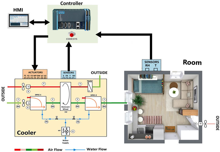
FIGURE 1. Cooler concept and its control system.
As shown in Figure 2, some sensors measure the temperature and relative humidity of the air in the room, atmosphere, and cooler. These values are sent to the controller along with a set of desired values input by the user/operator and evaluated. Consequentially, control signals are sent to the respective actuators, which run them at appropriate speeds. In the HIL testing of the designed control strategy, the Advantech AMAX is used as a controller and is programmed using CODESYS. CODESYS serves as an all-in-one development environment used to program controller applications based on the globally recognized industrial standard IEC 61131-3.
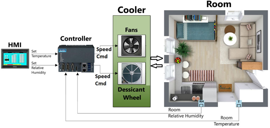
FIGURE 2. Control system components.
Its advantages lie in its compatibility with various controllers, support for multiple programming languages, user-friendly interface, extensive library support, multi-platform compatibility, remote access and monitoring capabilities, cost-effectiveness, rapid prototyping, strong community and support, and continuous development with regular updates. These features make CODESYS a versatile and efficient tool for industrial automation and control system projects. On the other hand, the IEC 61131-3 standard, established by the International Electrotechnical Commission (IEC), serves as a global framework for programming industrial control systems. It offers a comprehensive set of guidelines and rules for programming languages employed in the development of programmable logic controllers (PLCs) and other devices used in industrial automation.
HIL testing is a testing approach used for validating complex control systems. It involves creating mathematical models or simulations of components, developing hardware interfaces to connect real-time hardware with the simulation environment, defining test scenarios, and executing tests. During testing, real-time hardware interacts with the simulated environment, and data are collected and analyzed to assess system performance and compliance with requirements. Optional fault injection helps evaluate system robustness. The process includes debugging, issue resolution, and documentation. HIL testing allows developers to thoroughly validate control systems before deployment, ensuring functionality and reliability in a controlled environment. So, as the first step, it is necessary to start with the modeling of the cooling system. In this study, heat and mass transfer models for both the system and room developed by Demir et al. (2022a) and Demir et al. (2022b) were used. These models are summarized in the following section with their main equations.
2.1 Mathematical modeling
In this paper, the cooling system consists of three main parts: a cooler, a room, and actuators. By modeling both temperature and relative humidity changes in each section, the conditioning process under the influence of the atmospheric air taken into the cooler and the air fed from the cooler to the room is examined. The DC motor model is used for all actuators.
2.1.1 Model of the DPEC
2.1.1.1 Air temperature variation model in the cooler
The air fed through the fans
where
The temperature of the air at the outlet of the cooler is calculated by considering the heat gained because of this incoming atmospheric air (
where
2.1.1.2 Air relative humidity variation model in the cooler
Like the temperature model, the relative humidity variation model in DPEC is obtained by using the desiccant wheel speed and mass transfer relationship. First, the desiccant wheel speed is converted to a change in the vapor mass in the air.
In this equation,
where
2.1.2 DC motor model in the cooler
There are three actuators in these units: fans, a desiccant wheel, and a water pump. In the simulations, a simple DC motor model was used as the motor model for all actuators. The transfer function for this model, where the output is motor speed and the input is motor voltage, is given in the following equation (Pandelidis et al., 2020):
where
2.1.3 Model of the room
2.1.3.1 Air temperature variation model in the room
In this model, room temperature variations are calculated. Cold air from the cooler enters the room, cooling the room until it reaches equilibrium temperature. The heat loss due to cooling is calculated by using the air coming from the cooler and the actual air in the room.
where
where
2.1.3.2 Relative humidity variation model in the room
The relative humidity in the room is calculated similarly to the temperature variation model. The air at the outlet of the cooler is fed inside the room, and the relative humidity of the room is varied because of the introduction of air with lower relative humidity. The following equations are used for calculating the variation of the room’s relative humidity:
where
3 Control strategy
The performances of the actuators, such as fans and the desiccant wheel (the speed of these actuators), depend on the reference (setting) values and actual values of indoor temperature and humidity and the atmospheric temperature and humidity. If the differences between the reference and actual values of the indoor conditions are higher, the controller sends high input voltages to actuators, subsequently increasing their speeds. This leads to an increase in cooling and dehumidification performance. When the differences start to decrease, the speeds of the actuators are changed by the control strategy. Furthermore, the atmospheric temperature affects the cooling performance. If the temperature and relative humidity of the atmosphere are higher than the indoor and setting temperature and relative humidity, the controller sends higher voltages to actuators and tries to increase the performance of the cooling system.
Temperature and relative humidity are the variables to be controlled. This is achieved through actuators for the required variable. Sensor values are sent to the controller and are then compared to the set values by the operator/user. An error signal is then produced using a proportional gain; this error signal is adjusted by the controller or used by the controller to produce the required control inputs for the actuators, in this case, a voltage. The produced voltage is sent to the actuators, changing the desired variables (temperature and relative humidity) accordingly. However, outside factors that may affect temperature and relative humidity, such as windows, humans, outdoor conditions, and actuator warmup, must be taken into consideration. By taking these factors into account, a more complete control strategy that would keep the room under desired conditions can be implemented. In addition, accounting for these factors would bring the control logic closer to being as fault-proof as possible for real-time hardware implementation.
In this study, the P controller is selected for the control strategy. It offers simple implementation, stability, fast response, and linear control action. It effectively reduces steady-state error and is not prone to integral windup issues, making it robust in some applications. The P controller can be combined with other control strategies to create more advanced control systems like PID controllers, which provide improved performance and can handle non-linear systems. However, it may not be suitable for all control tasks, particularly in systems with significant disturbances or complex control requirements.
where
3.1 HIL testing concept
After designing the control strategy, the operation of the control system was tested by the HIL test. As previously stated, Advantech AMAX 5580 PLC and CODESYS software were used as controllers. In addition, the HMI is designed for the user to enter reference values. HIL testing is vital in the development and validation of complex control systems due to several key reasons. It provides a realistic testing environment by allowing real hardware to interact with simulated components, ensuring the system’s behavior aligns with expectations before real-world deployment. HIL testing enables early issue detection, reduces development time and costs, and validates safety-critical systems without posing risks to human lives or expensive equipment. It allows testing under extreme conditions, reusing test scenarios, and automating processes for faster development cycles. HIL testing also facilitates easier debugging, analysis, and compliance with industry standards, enhancing the reliability, performance, and safety of control systems. As shown in Figure 3, there are three phases to embedded control software development. Phase 1 is desktop engineering, where everything is conducted on a desktop PC or laptop, and the plant model and control logic are both developed in simulation software. Phase 2 is HIL testing, where control logic runs on a targeted ECU/PLC and the plant model runs on a HIL simulator on a different ECU/PLC in real time. Phase 3 is actual machine testing, where the control algorithm runs on a targeted ECU/PLC connected to actual machine working in real time, the targeted ECU is monitored, and controller parameters are tuned. This paper will focus on Phase 2, HIL testing.
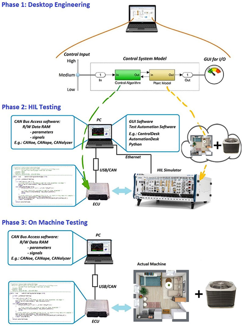
FIGURE 3. Three phases of embedded control software development.
The method of communication used in HIL testing is “Modbus TCP/IP” using CODESYS. Using two ECUs/PLCs, a laptop/PC for development purposes and functioning as an HMI device and RJ-45 cables, communication can be set up. Modbus TCP is simply a variation of Modbus RTU; however, instead of the traditional serial RS-232 communication, a library/interface is utilized that runs on Ethernet. Modbus TCP is commonly used in automation for various applications, including, but not limited to, connecting to HMIs, PLCs, actuators, and sensors. In this communication protocol, a master and slave exist, with the master containing the control logic to control the required device and the slave containing the programs to simulate the required device. Master and slave programs are uploaded onto separate PLCs using a laptop/PC. After ensuring successful communication through Ethernet, one can now run the programs to obtain HIL test results. A total of eight variables are being sent and received in this HIL test, which are actual temperature, actual relative humidity, atmospheric temperature, atmospheric relative humidity, desired temperature, desired relative humidity, fan voltage, and desiccant wheel voltage. In Figure 4, a real-time HIL test can be observed. As previously mentioned, there is a master controller, which is the “ECU/PLC with the control logic,” and a slave HIL simulator, which is the “ECU/PLC with cooler and room model,” both of which are shown in Figure 4. Both ECUs/PLCs communicate through Modbus; the master controller is responsible for sending the fan voltage and the desiccant wheel voltage. These values are determined by the master controller, which receives both the desired temperature and relative humidity as well as both the actual room temperature and relative humidity. It should be noted that the desired values are set by the user/operator, which is achieved through “controller HMI,” as shown in Figure 4. The slave HIL simulator that contains the actual room temperature and relative humidity would then start to run the model. Since the master controller receives the desired temperature and relative humidity commands, it sends fan and desiccant wheel voltages to the slave HIL simulator. The temperature and relative humidity of the room in the slave HIL simulator decrease with time until they reach the desired conditions. The results and behavior of the manipulated variables can be observed on the “cooler and room model HMI,” as shown in Figure 4.
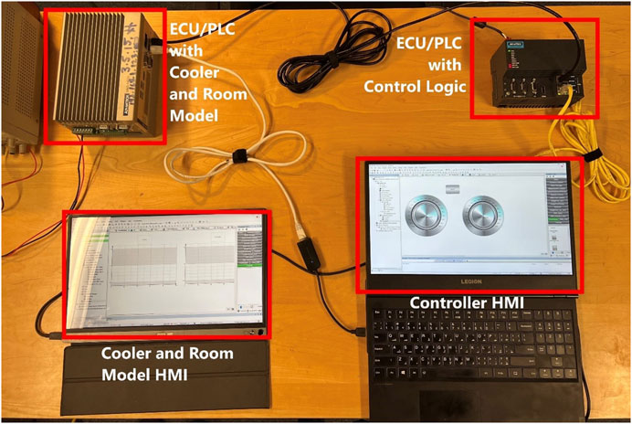
FIGURE 4. Real-time HIL testing setup.
4 Results and discussion
Recording the results obtained from MATLAB/Simulink simulation and CODESYS HIL testing, a comparison of the behavior of the system is conducted. Simulations are necessary in the early stages of control design. Simulations are used to predict the behavior of a system without physically building it. However, HIL testing is necessary to represent how the complex system will behave in an actual environment and validate the control logic, detecting any faults and allowing for control logic optimization. Traditionally, an HIL test can be expensive; however, using CODESYS allows for a more widely available HIL test. A total of four tests are conducted, two for each control variable (temperature and relative humidity). Each of the two tests is conducted under different initial conditions to validate the control logic implemented in the simulations. While the simulation results provide theoretical predictions of system behavior, HIL test results provide real-time results based on real hardware and its integration with the simulation environment, showing a more realistic result of system behavior.
The first test was conducted to observe the room temperature behavior when the atmospheric temperature was greater than the temperature inside the room; the test was conducted in both simulation and HIL to compare results. As shown in Figure 5, both results show very similar behavior with minor differences. Upon closer examination of the results, the operation modes of the cooler can be distinctly observed. The first 90 s show the cooler in the OFF mode (fans OFF), and the temperature can be seen increasing slightly due to outside factors. When the cooler turns ON (fans ON), the warmup mode can be observed for 60 s, where the fans directly push atmospheric air into the room. The room’s temperature increases due to the atmospheric temperature being higher than the temperature of the room. Once the warmup mode subsides, active cooling mode starts, actively cooling the room until desired conditions are met. Once the desired conditions are met, the fans continue to provide cool air to keep the room temperature in the desired range. The results show that the HIL room temperature decreases at the same rate as that of the simulation room temperature, showing similar overall behavior; this validates the model and ensures the accuracy of the control logic. The minor differences in the behavior can be attributed to multiple factors, such as different numerical solvers used and software limitations for the HIL test (CODESYS). It is also worth noting that in HIL, the plant model, in this case, the room and cooler, is simpler than in simulation, mainly due to the solver used in CODESYS, while MATLAB/Simulink provides a solver for the model. Stateflow implementation in Simulink for dynamic decision-making was also used, which explains the difference in the behavior of different modes. In CODESYS, the solver was coded into the program on the slave HIL simulator, leading to a difference in the rate of heat gain and loss throughout the simulation.
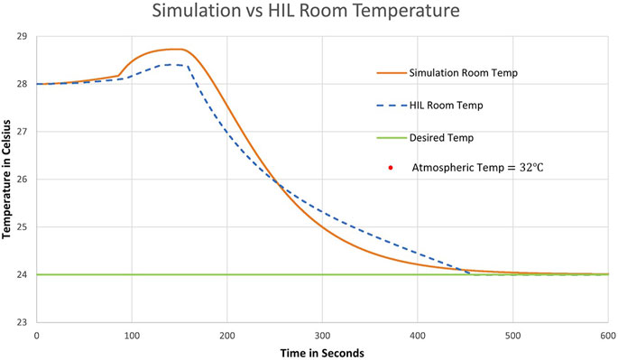
FIGURE 5. Test 1: room temperature. Simulation results vs. HIL test results. The atmospheric temperature is higher than the room temperature.
The second test was conducted to observe the room temperature when the atmospheric temperature is lower than the room temperature. In Figure 6, for the first 90 s, the cooler is in the OFF mode (fans OFF), and the temperature can be seen slightly increasing due to disturbances. The cooler then turns ON (fans ON), and the warmup mode can be seen for 60 s (90 s–150 s). Unlike the previous case in Figure 5, the room temperature decreases in the warmup mode; this is due to the atmospheric temperature being lower than the room temperature. It can also be observed that while the cooler is in the warmup mode, the fans are rotating at a constant speed (constant voltage being supplied) as the temperature decreases in an almost linear line in the HIL test (expected behavior). Active cooling is then turned on, and proportional control starts, supplying a varying voltage to the fans and decreasing the room temperature until the desired conditions are met. Once the desired conditions are met, the cooler works against any disturbances that may arise, keeping the room under those conditions. The results are similar in behavior, further confirming the validity and accuracy of the control logic even when dealing with different initial conditions, such as the atmospheric temperature being greater or less than the room temperature.
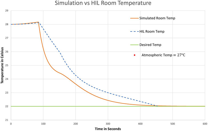
FIGURE 6. Test 2: room temperature. Simulation results vs. HIL results. The atmospheric temperature is less than the room temperature.
The third test was conducted to observe the room’s relative humidity when atmospheric relative humidity is greater than the room’s relative humidity. In Figure 7, for the first 90 s, the cooler is in the OFF mode (desiccant wheel OFF), and relative humidity can be observed slightly increasing due to outside disturbances. The cooler then turns ON (desiccant wheel ON), and the warmup mode starts for 60 s. During these 60 s, relative humidity can be observed to be significantly increasing; this is due to the desiccant wheel supplying the room with humidity directly from the atmosphere. After warmup, active cooling is turned on, and the room’s relative humidity can be observed steadily decreasing until desired conditions are met. Once desired conditions are met, the cooler works against any disturbances to keep the room under the desired relative humidity condition. The behaviors between the simulation and HIL results are similar, with the main difference being in the warmup mode. This can be explained due to the software limitations of CODESYS. Since itis mainly a development environment for PLCs, it does not have built-in features for solving differential equations. While this is the case in all tests, it stood out the most when handling mass transfer. Another limitation could also be due to the lack of a similar logic-based decision-making feature, such as Stateflow, that was used in the simulation results. The result of the HIL test in this case is promising; however, it verifies the control logic and ensures that the control logic would behave as expected under real-world conditions, which is the main goal behind these tests.
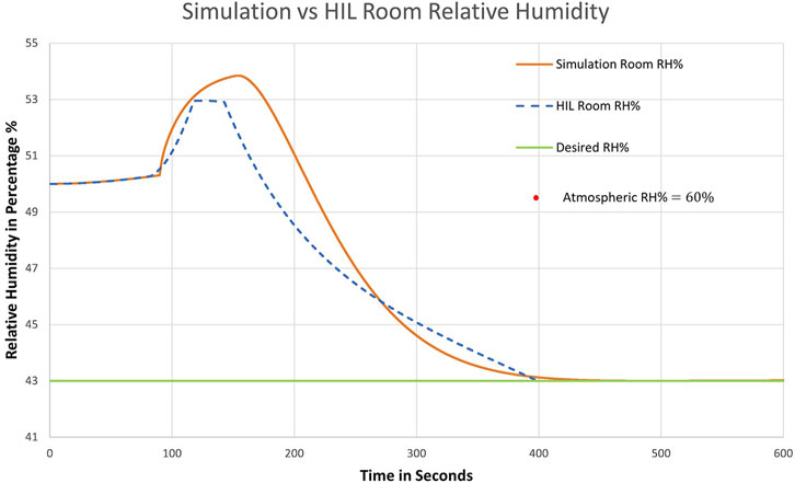
FIGURE 7. Test 3: room relative humidity. Simulation results vs. HIL test results. Atmospheric relative humidity is larger than room relative humidity.
The third test was conducted to observe the room’s relative humidity when the atmospheric relative humidity is less than the room’s relative humidity. In Figure 8, the first 90 s represent the cooler in the OFF mode, and the relative humidity of the room can be seen increasing slightly due to disturbances. The cooler then turns on, entering the warmup mode for 60 s. In the warmup mode, the room’s relative humidity can be observed to be decreasing steadily; this is due to the desiccant wheel supplying the room with the less humid outdoor relative humidity at a constant speed. Once the desiccant wheel has been warmed up, the cooler then enters the active cooling mode, decreasing the relative humidity until the desired room conditions are met. In this test, the HIL result behavior can be seen to be similar to the simulation result behavior, with minor differences. This verifies the control logic and validates system functionality.
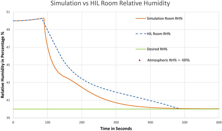
FIGURE 8. Test 4: room relative humidity. Simulation results vs. HIL test results. Atmospheric relative humidity is less than room relative humidity.
All four HIL tests were conducted using two PLCs and the CODESYS development environment. Communication was established using Modbus TCP. The results validated the control logic designed for the DPEC and system functionality. Two use cases were considered for the test, atmospheric variables (temperatures and relative humidity) greater than and less than room variables. This allowed for further investigation into what the limitations of the HIL test may be. Furthermore, the tests verified the reliability of the communication method. Using Modbus TCP, the control algorithm responded to the inputs from the simulation environment instantly, and commands were constantly sent accordingly (voltage commands to fans and the desiccant wheel). The response of the system to the received commands matched the predictions derived from simulation results. While there are some discrepancies, these can mainly be due to CODESYS not being simulation software (different differential solver and lack of stateflow counterpart).
5 Conclusion
In this study, an independent temperature and relative humidity proportional control for a super-efficient air-cooling system is tested using HIL technology. The HIL test was conducted with real-time controllers using two industrial PCs and CODESYS and Modbus TCP communication. The objective is to validate the offline simulation results obtained using MATLAB/Simulink using the real-time implementation of the controller and plant model. The HIL tests were conducted by using one PLC as an HIL simulator and another PLC containing the control logic; information is exchanged between the two PLCs using standard communication protocols. Using proportional control, the fan and desiccant wheel speed are adjusted to control the air flow rate, thereby decreasing temperature and relative humidity, respectively. The results obtained through HIL were in line with the offline simulation results with minor differences, confirming the efficacy of the control logic and bringing it one step closer to final implementation on the actual cooling system. In this study, it is assumed that some parameters of the system do not change and remain constant throughout the tests. In addition, the temperature and humidity are the same everywhere in the room, and the effects of the disturbing effects added to the room on both the relative humidity and the temperature are taken as average. In future studies, using a more adaptive strategy as a control strategy can increase the robustness and precision of the system. In addition, control performance can be tested under varying conditions. Although the atmosphere and room and system conditions change at the time of the test, tests can be conducted on the control performance.
Data availability statement
The original contributions presented in the study are included in the article/Supplementary Material; further inquiries can be directed to the corresponding author.
Author contributions
Conceptualization: DP, OH, MD, SC, WW, and JP; methodology: OH, MD, DP, and SC; software: OH, SC, and MD; investigation: OH, SC, MD, DP, and WW; resources: DP; writing—original draft preparation: OH and MD; writing—review and editing: SC, DP, and WW; visualization: OH and SC; supervision: SC, DP, and WW; project administration: DP; and funding acquisition: DP. All authors contributed to the article and approved the submitted version.
Funding
This research was funded by the Polish National Centre for Research and Development, program Lider X, agreement number U/0180/666/2019, the European Regional Development Fund, industrial research and development works conducted by enterprises, under the competition 1/1.1.1/2021 Fast Track of the Intelligent Development Operational Program 2014–2020, agreement number 11IR/0011/2021, and the Polish National Agency for Academic Exchange (Bekker program), agreement number BPN/BEK/2021/2/00014/U/00001/A/00001.
Conflict of interest
Author JP and DP were employed by Baryon Inc.
The remaining authors declare that the research was conducted in the absence of any commercial or financial relationships that could be construed as a potential conflict of interest.
Publisher’s note
All claims expressed in this article are solely those of the authors and do not necessarily represent those of their affiliated organizations, or those of the publisher, the editors, and the reviewers. Any product that may be evaluated in this article, or claim that may be made by its manufacturer, is not guaranteed or endorsed by the publisher.
References
Asim, M., Saleem, S., Imran, M., Leung, M., Hussain, S., Miró, L., et al. (2019). Thermo-economic and environmental analysis of integrating renewable energy sources in a district heating and cooling network. Energy Effic. 13, 79–100. doi:10.1007/s12053-019-09832-9
Blasco, C., Monreal, J., Benítez, I., and Lluna, A. (2012). “Modelling and PID control of HVAC system according to energy efficiency and comfort criteria,” in Sustainability in energy and buildings (Berlin, Germany: Springer), 365–374.
Caliskan, H., Lee, D., and Hong, H. (2020). Assessments of high-efficient regenerative evaporative cooler effects on desiccant air cooling systems. J. Energy Resour. Technol. 142, 072101. doi:10.1115/1.4046523
Chen, Y., Yan, H., Luo, Y., and Yang, H. (2019). A proportional–integral (PI) law based variable speed technology for temperature control in indirect evaporative cooling system. Appl. Energy 251, 113390. doi:10.1016/j.apenergy.2019.113390
Chen, Y., Yan, H., and Yang, H. (2018). Comparative study of on-off control and novel high-low control of regenerative indirect evaporative cooler (RIEC). Appl. Energy 225, 233. doi:10.1016/j.apenergy.2018.05.046
Demir, M. H., Cetin, S., Haggag, O., Demir, H. G., Worek, W., Premer, J., et al. (2022a). Design of a proportional control based advanced control strategy for independent temperature and humidity control of a pre-cooled desiccant air-cooling system. Appl. Sci. 12 (19), 9745. doi:10.3390/app12199745
Demir, M. H., Cetin, S., Haggag, O., Demir, H. G., Worek, W., Premer, J., et al. (2022b). Independent temperature and humidity control of a precooled desiccant air cooling system with proportional and fuzzy logic + proportional based controllers. Int. Commun. Heat Mass Transf. 139, 106451. doi:10.1016/j.icheatmasstransfer.2022.106451
Dincer, I., and Rosen, M. (2007). “Exergy analysis of psychrometric processes,” in Exergy: Energy, environment and sustainable development. 1st ed. (Amsterdam, Netherlands: Elsevier Science), 76–90.
Elahi, S., and Farhani, S. (2021). Increasing evaporative cooler efficiency by controlling water pump run and off times. Int. Commun. Heat. Mass Transf. 127, 105525. doi:10.1016/j.icheatmasstransfer.2021.105525
Gao, W., Worek, W., Konduru, V., and Adensin, K. (2015). Numerical study on performance of a desiccant cooling system with indirect evaporative cooler. Energy Build. 86, 16–24. doi:10.1016/j.enbuild.2014.09.049
Goldsworthy, M., and White, S. (2011). Optimisation of a desiccant cooling system design with indirect evaporative cooler. Int. J. Refrig. 34, 148–158. doi:10.1016/j.ijrefrig.2010.07.005
Huang, W., and Lam, H. (1997). Using genetic algorithms to optimize controller parameters for HVAC systems. Energy Build. 26, 277–282. doi:10.1016/s0378-7788(97)00008-x
International Energy Agency Report (2021). Net-Zero by 2050 a Roadmap for the Global Energy Sector. Paris, France: IEA Publications
Li, Z., Xu, X., Deng, S., and Pan, D. (2015). A novel neural network aided fuzzy logic controller for a variable speed (VS) direct expansion (DX) air conditioning (A/C) system. Appl. Therm. Eng. 78, 9–23. doi:10.1016/j.applthermaleng.2014.12.030
Lin, J. L., and Yeh, T. J. (2009). Control of multi-evaporator air-conditioning systems for flow distribution. Energy Convers. Manag. 50 (6), 1529–1541. doi:10.1016/j.enconman.2009.02.018
Narayanan, R., Halawa, E., and Jain, S. (2018). Performance characteristics of solid-desiccant evaporative cooling systems. Energies 11, 2574. doi:10.3390/en11102574
Pacak, A., and Worek, W. (2021). Review of dew point evaporative cooling technology for air conditioning applications. Appl. Sci. 11, 934. doi:10.3390/app11030934
Pandelidis, D., Anisimov, S., Worek, W., and Drag, P. (2016). Comparison of desiccant air conditioning systems with different indirect evaporative air coolers. Energy Convers. Manag. 117, 375–392. doi:10.1016/j.enconman.2016.02.085
Pandelidis, D., Anisimov, S., Worek, W., and Drag, P. (2017). Analysis of different applications of Maisotsenko cycle heat exchanger in the desiccant air conditioning systems. Energy Build. 140, 154–170. doi:10.1016/j.enbuild.2017.01.067
Pandelidis, D., Pacak, A., Cichon, A., Drag, P., Worek, W., and Cetin, S. (2020). Numerical and experimental analysis of precooled desiccant system. Appl. Therm. Eng. 181, 115929. doi:10.1016/j.applthermaleng.2020.115929
Peng, D., Zhou, J., and Luo, D. (2017). Exergy analysis of a liquid desiccant evaporative cooling system. Int. J. Refrig. 82, 495–508. doi:10.1016/j.ijrefrig.2017.06.021
Qi, Q., and Deng, S. (2009). Multivariable control of indoor air temperature and humidity in a direct expansion (DX) air conditioning (A/C) system. Build. Environ. 44, 1659–1667. doi:10.1016/j.buildenv.2008.11.001
Yan, H., Chen, Y., and Zhang, W. (2019). Year round based optimization of high-low control in the regenerative indirect evaporative cooler (RIEC). Sci. Technol. Built Environ. 25, 1394–1405. doi:10.1080/23744731.2019.1620576
Yan, H., Xia, Y., and Deng, S. (2017). Simulation study on a three-evaporator air conditioning system for simultaneous indoor air temperature and humidity control. Appl. Energy 207, 294–304. doi:10.1016/j.apenergy.2017.05.125
Keywords: hardware-in-the-loop, energy efficiency, CODESYS RTE, controller design, evaporative coolers
Citation: Haggag O, Demir MH, Cetin S, Worek W, Premer J and Pandelidis D (2023) Hardware-in-the-loop testing of control of a precooled desiccant air-cooling system. Front. Mech. Eng 9:1228466. doi: 10.3389/fmech.2023.1228466
Received: 24 May 2023; Accepted: 04 August 2023;
Published: 17 August 2023.
Edited by:
Sohel Anwar, Indiana University, Purdue University Indianapolis, United StatesReviewed by:
Ahmet Çağdaş Seçkin, Adnan Menderes University, TürkiyeKhaled Ali, American University in Dubai, United Arab Emirates
Copyright © 2023 Haggag, Demir, Cetin, Worek, Premer and Pandelidis. This is an open-access article distributed under the terms of the Creative Commons Attribution License (CC BY). The use, distribution or reproduction in other forums is permitted, provided the original author(s) and the copyright owner(s) are credited and that the original publication in this journal is cited, in accordance with accepted academic practice. No use, distribution or reproduction is permitted which does not comply with these terms.
*Correspondence: Osama Haggag, b2hhZ2dhMkB1aWMuZWR1