 Jurij Prezelj
 Nejc Cerkovnik
- Faculty of Mechanical Engineering, University of Ljubljana, Ljubljana, Slovenia
This paper proposes innovative numerical methods for calculating the chamber volumes and tangential leakage gaps in a scroll compressor, a critical aspect of enhancing its performance and efficiency. It proposes two methods, namely, moving away from traditional analytical approaches and presenting a 0D model for mass flow delivery at varying rotational frequencies and discharge pressures. The first method utilizes the numerical identification of conjugate points with a minimum distance within the fixed and orbiting involute pair to calculate chamber volumes. This approach compensates for integration errors by considering the subareas defined by the normal distance of each involute to the other. The second method simplifies the process by assuming that the line defining the orbital angle intersects the involutes at the conjugate points, with volumes calculated using area discretization on triangles. Both methods underwent validation against three analytical calculations, showing an agreement within an overall uncertainty error of 3% for the maximum suction volume. The 0D model’s results were compared with Ma et al.'s hybrid method and actual measurements. Upon improving Ma’s model by accounting for intake air heating and negative pressure in the intake volume, a significant agreement between modeling and measurements was observed. This study concludes that the proposed numerical methods can enhance the accuracy of scroll compressor geometry calculation and mass flow delivery, considering the tangential gap.
Highlights
- Numerical calculation of scroll geometry based on parallel involutes is demonstrated by two different methods and compared with three analytical methods.
- The hybrid model provided by Ma et al. is improved for the influence of the intake gas heating and for the pressure drop during the intake of fresh gas into the suction volume.
- A 1D model for the mass flow delivery of the scroll compressor based on numerically obtained geometry data provides results that agree well with measurements.
1 Introduction
The concept of a machine with orbiting blades, which determines the basic principles of today’s scroll compressors, was proposed by Creux as early as 1905. With the development of production technologies that made it possible to produce complex arbitrary shapes of the scrolls, the scroll compressor became practically feasible and eventually very popular. Scroll compressors are based on spiral blades, i.e., scrolls, which are paired to create a multi-chamber geometry. While one scroll is fixed, the other one orbits it. A specific relative motion creates moving and shape-changing multiple chambers. The volume of the moving chambers shrinks with the angle of the orbit. Scroll compressors are now widely used in the gas compression industry due to their high compression efficiency, low noise emissions, high reliability, and low maintenance costs (Chen et al., 2002a; Winandy et al., 2002; Mendoza et al., 2017). An inherent advantage of scroll compressors compared to other volumetric compression machines is the longer available time for the compression and discharge processes (Evandro et al., 2020). Therefore, they are gradually being used in compressed air energy storage systems, where they can also be used as expanders (Dumont et al., 2018; Fanti et al., 2020; Wang et al., 2021a). The use of a scroll compressor as a vacuum pump has also been tested (Wang et al., 2021a). However, scroll compressors are now mainly used in applications where low noise and vibration levels are important, such as residential heat pumps, residential cooling systems, and air conditioning systems.
Unique properties of scroll machines have attracted the attention of scientists and industrial researchers. The fundamentals of their operation are well known today and have been worked out analytically, experimentally, and by using CFD methods. The mechanism of the scroll compressor is understood, and the relationship between the chamber volume and orbit angle is derived (Chen et al., 2002a; Wang et al., 2005; Bell et al., 2012). However, the derivation still requires numerous calculations, and the models are not as suitable for generalization as they could be. The design of the scroll profile, which plays a crucial role in determining the performance, is still a key element in the development of scroll compressors (Bell et al., 2010; Mojiri et al., 2019). The geometry of the scroll profile determines the efficiency of the device, and it is critical to accurately model the volume changes in the chambers during orbiting (Bell et al., 2010). Since the suction process has a significant impact on the performance of scroll compressors (Sun et al., 2020), its design usually begins with the geometry of the scroll to determine the geometry of the inlet/intake, i.e., the suction volume.
The geometry of the scroll compressor is generally based on a pair of parallel involutes and their mirrored pair, although multi-bladed, i.e., polygonal involute scrolls (Qiang and Liu, 2013; Wang J. et al., 2022), and Archimedean spiral scrolls (Shaffer and Groll, 2013) have also been successfully demonstrated. The geometry of scrolls is always given in the parametric form. Most geometric analyses of scroll compressors and expanders in the available literature are based on purely analytical principles, numerical principles derived from Green’s theorem, or directly implemented in the CFD models. Chen et al. (2002a) developed an analytical solution for the chamber area based on the involute initial angles. Later, Wang et al. (2005) proposed a more general method with a discretionary starting angle. The improved geometric analysis of Wang et al. (2005) can be used with reasonable accuracy, but the comprehensive geometric model of Bell et al. (2012) is recommended. Bell et al. (2014) implemented a polygon-based integration using Green’s theorem to calculate the area/volume of working chambers in scroll machines with constant wall thickness. Shaffer and Groll (2013) showed that the scroll compressor can be modified from its traditional circular involute design by using (a) a first order, (b) first order with offset, (c) second order, and (d) third-order Archimedean spiral in combination with a variable wall thickness. Wang et al. (2021b) showed that asymmetrical scroll wraps can be designed at the involute start, i.e., the compressor outlet or the vacuum pump/expander inlet. Much of the research has been devoted to the geometry of the vanes at the outlet of the scroll compressor, i.e., the involute at the start (Ding et al., 2021). This is important to achieve higher pressure differences, which can be easily achieved by lengthening the involute or increasing the apparent compression stages. In addition, a set of analytical and exact equations for calculating the compression chamber volume of a co-rotating scroll compressor was introduced by Mojiri et al. (2020a), but the numerical implementation of Green’s theorem was used to realize a larger scroll compressor model. The CFD method was also presented to analyze the geometry of scroll compressors (Zhang et al., 2022). Wang et al. (2023) used CFD/CSM methods to study changes in radial and flank leakage gaps and were validated with experiments. The calculation of chamber areas in asymmetric algebraic scroll compressors using Green’s theorem is presented by Wang C. et al. (2022).
Although the principles are well known, the everlasting goal of improving the efficiency of scroll compressors remains and the geometry of scrolls still plays an important role in research (Cordone and Gargiulo, 2020). In addition to geometry optimization, the literature also contains numerous studies on thermodynamic modeling supported by experimental investigations. Various approaches have been used to improve the efficiency of scroll compressors, such as researching the design of rotor profiles to reduce volumetric losses (Lee and Wu, 1995; Ishii et al., 1996) and studying the effects of cooling on compression work (Xudong et al., 2008; Shuaihui et al., 2010). Individual processes that occur in the compressor have been modeled, such as compression (Chen et al., 2002a), heat transfer (Pereira and Deschamps, 2017; Rak and Pietrowicz, 2020; Wang J. et al., 2022), and leakage (Chen et al., 2002b). Full simulation models have also been created (Chen et al., 2002a; Chen et al., 2002b; Bell, 2011; Ziviani et al., 2020). In addition to traditional scroll compressors, co-rotating (Mojiri et al., 2019; Mojiri et al., 2020b), double scroll (Wang J. et al., 2022), and flooded compressors (Bell et al., 2012) have also been modeled. Theoretical models reflect the compressor performance and can provide insights into various scenarios that cannot be achieved with experimental or CFD analyses. During the compression process, many important process parameters of a scroll compressor are difficult to measure. The operating conditions of the system in which the scroll compressor is integrated vary greatly depending on the power requirements, i.e., pressure and mass flow. Therefore, it is necessary to predict the performance of the compressor over a wide range of operating conditions. Models based only on physical mechanisms or only on data mining cannot meet the overall accuracy and practicality over a wide range of operating conditions. Ma et al. (2019) proposed a hybrid modeling method for scroll compressors that combines integral features of physical mechanisms and data analyses.
In the available literature, the chamber volumes are calculated using integral equations derived from a parametrically given equation for the spiral/involute, or they are calculated numerically using the integration of boundary curves according to Green’s theorem. Although the involute geometry calculations are straightforward, the analytical expressions and Green’s integral expressions are cumbersome to implement, except for the integrals of straight line segments. The analytical approach has its advantages, but ultimately, it is still necessary to perform some numerical calculations. Therefore, we have approached the design of the scroll geometry and the computation of the chamber volumes purely numerically, avoiding an analytical approach and the computation of centroids, anti-derivative functions, and derivative functions, which are necessary when solving surface integrals of contours enclosed with involutes using Green’s theorem (Bell et al., 2014). The simplicity of the proposed methods helps implement them in calculations of new scroll wrap designs and include them in the overall modeling of compressors, increasing the efficiency of the whole design process. With the increase in the computational efficiency may come some loss of accuracy in the results produced, but we also show that the proposed methods still provide calculations of chamber values accurate enough to evaluate the performance of scroll compressor delivery.
Two purely numerical approaches are proposed in this paper. The first approach is based on the calculation of the distances between two blades/scrolls enclosing the working volume. The tangential/flank distance is then used to calculate/estimate the area between two conjugate points, as described in the proposed method A. In the second approach, the area between two scrolls defined by two conjugate points is discretized into triangles, as described in the proposed method B. Methods A and B for calculating the suction volume in discrete space are simple to implement, understand, and use. The methods avoid analytical integrations and the use of Green’s theorem, so they can be used in scientific and engineering studies of scroll compressors. They can be used in the initial stages of the scroll compressor design and for further modeling.
Validation of the numerical calculation of scroll geometry and the chamber volume has been performed by comparison with other available methods based on analytical solutions. A method for the delivery of scroll compressors based on numerical calculations of the geometry is also presented. The method takes into account gas compression, leakage, and heat transfer. The method was validated by experiments and compared with the hybrid model proposed by Ma et al. (2019), which was slightly improved in terms of suction efficiency. The proposed modeling of a scroll compressor allows rapid prediction of mass flow as a function of discharge pressure, rotational/orbital frequency, and temperature. It also describes the operation of a scroll compressor over a wide operating range.
2 Proposed method A
The background of the proposed numerical method is presented in Figure 1. The shortest distance from the selected point on curve B to curve A can be obtained by drawing a circle from the center at the selected point on curve B with radius
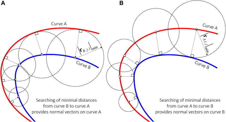
FIGURE 1. The shortest distance between two curves defines the direction of the normal vector to one of the curves, depending on the sequence of inscribing the circle. (A) Inscribing circle from curve A to curve B; (B) inscribing circle from curve B to curve A.
The shortest distance from the selected point on curve A to curve B can be obtained by drawing a circle from the center at the selected point on curve A with radius
2.1 Numerical detection of conjugate points
Curves defining the geometry of the scroll compressor blades are typically from the family of involutes. Two parallel involutes are parametrically defined using Eq. 1:
where φ stands for the angle of the involute, ϑ for the orbiting angle, rb for the basic radius of the involute, r0 for the orbiting radius, and α0 for the starting angle. To define the geometry for each orbiting angle ϑ, four sets of points describing four involutes must be calculated for the selected range of involute angles from φ0 to φmax, where φmax defines the length of the scroll i.e., the number of turns of the involute and hence the compression ratio. The basic radius rb and the starting angle α0 define the thickness of the blade and hence the orbiting radius r0. If the orbiting radius r0 is defined by a selected Oldham coupling mechanism, the basic radius rb and the starting angle α0 must be appropriately selected.
The tangential gap between the two scrolls, denoted as g, is fundamentally influenced by the basic radius (rb) and the starting angle (α0). Ideally, this gap should be minimized to improve the efficiency, but a very small gap may result in contact and sliding between the scrolls, leading to wear and decreased performance. As such, machining accuracy becomes a key factor in the determination of rb and α0. An iterative approach can be employed to estimate these parameters from a predefined tangential gap, which is typically established based on the machining tolerance and the design constraints that aim to minimize leakage. In operational terms, the gap g is the minimum distance between the two involutes during the compressor action and should align with the desired machining tolerance. Calculating rb and α0 for a given gap is a complex task as it requires careful consideration of the scrolls' geometry and motion. However, a simplified iterative method can be applied as follows:
Step 1. Commence with an initial guess for rb and α0.
Step 2. Compute the gap using the provided involute equations and these initial parameter estimates.
Step 3. If the calculated gap exceeds the desired gap, increase rb or decrease α0 (or both) and then return to Step 2. Conversely, if the calculated gap is smaller than the desired gap, decrease rb or increase α0 (or both) and then return to Step 2.
Step 4. Repeat this process until the calculated gap approximates the desired gap as closely as possible.
This method provides a simplified yet practical approach for estimating rb and α0. Although it may not offer complete accuracy due to its simplifications, it serves as an effective starting point for parameter estimation based on a machining tolerance-defined gap.In this paper, the involute angle range was selected from φ = 0 to φmax = 25.12, for rb = 3 mm and ro = 5 mm, with starting angle α0 = ± 0.735 rad. The resolution of involutes plays an important role in the numerical calculation of geometry. A resolution of 50 points per radian results in 1,256 points to describe the involute, and a resolution of 400 points per radian results in 10,048 points to describe the involute.During the numerical calculation of the involutes, their Cartesian coordinates are calculated for each orbiting angle. Discretized points are symbolically shown on the involute in Figure 2. The consecutive numbers i and j of each point on the involute increase from the beginning of the involute. The length of the inner and outer involutes is different. Consequently, the number of points describing the inner and outer involutes is also different (N ≠ M). Figure 2 shows two adjacent involutes enclosing the working volume. The working volume is bounded by two marked points. The marked points are defined where the distance between two adjacent involutes is the smallest, which represents the point where the volume is closed, i.e., the conjugate points k and k + 1 between the involutes. The distance between all points can be calculated from involute A to involute B (red) and from involute B to involute A (blue) by using two basic equations, i.e., Eqs 2, 3.
and
The matrices
and
By extracting the minima from each row of the matrix, new vectors
and
Components of vectors
1. For the adjustment of blade thickness by adaptively selecting the starting angle of the involute α0;
2. For the automatic numerical detection of the conjugate point during orbiting of one involute around another which is necessary for the calculation of the chamber surface;
3. Calculation of the chamber surface defining the working volume enveloped by the two adjacent involutes;
4. Estimation of the tangential/flank gap g.
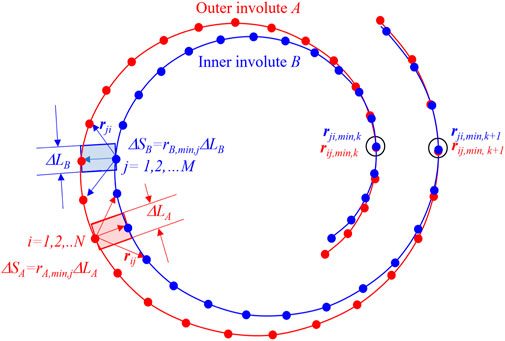
FIGURE 2. Vectors between each point on the inner involute and each point on the outer involute can be defined, and their length is calculated.
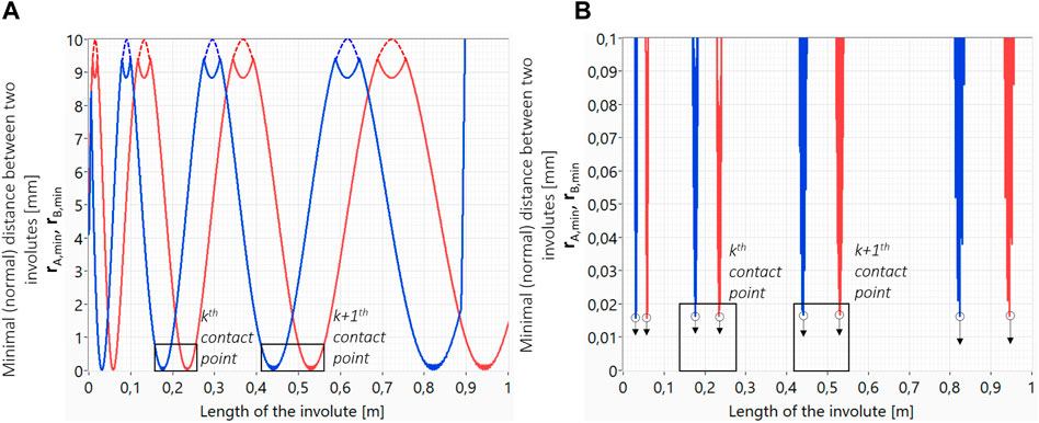
FIGURE 3. Distance between two involutes extracted from matrices RA and RB is shown on the left (A). Minimum values represent the tangential/flank gap, i.e., the clearance between two involutes at points closing the observed chamber (B).
2.2 Estimation of the surface area between two involutes defined by their two conjugate points
For the calculation of the surface area of the working chamber, the distance between two adjacent points on the involute is multiplied with the distance between two adjacent involutes, as marked with two rectangles in Figure 4. The following equation was used to calculate the width of the rectangle:
and
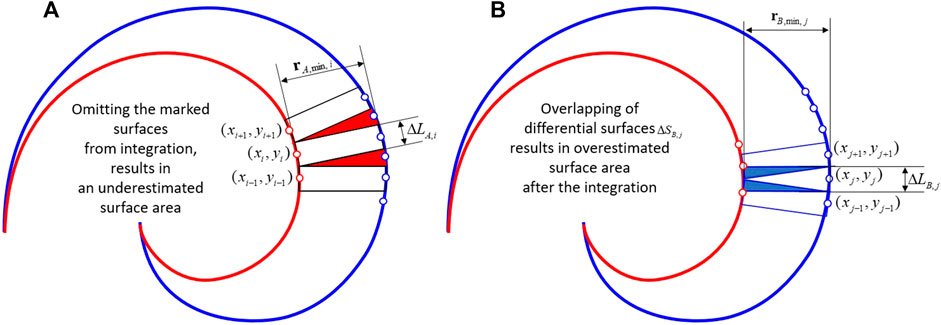
FIGURE 4. Integration of partial surface areas along the involute in two directions, from the inner involute to the outer (A) and from the outer involute to the inner (B). Integration error due to simplification of integration is minimized by averaging two results.
Due to different sizes of involutes, the distances differ from one coordinate number to the other.
The size of the rectangle can be simply calculated as
and
Two estimated surface areas SA and SB can be obtained by integrating the partial surface areas along the involute from one conjugate point to the other. Integration of partial surface areas
and
The described simplification in the integration of partial surfaces causes an error, which is canceled out with the doubling of the partial surfaces, from the direction of involute A to involute B and from the direction of involute B to involute A, as shown in Figure 4. While one result is overestimated, the other result is underestimated, as shown in Figure 4. Overestimation is marked with red triangles, and underestimation is marked with blue triangles. The integration error, which occurs due to described simplification, can be, therefore, cancelled by averaging the two results, Eq. 15.
Conjugate points between the fixed and orbiting involutes define the surface areas of the chambers at a given orbital angle, as shown in Figure 5 previously. The distances between the fixed involute and the orbiting involute are different from the distances between the orbiting involute and the fixed involute because their lengths are not equal, as shown in Figure 5 in the following section. Figure 5 shows the difference in the estimated distance between the involutes for the normal vector to involute A (blue) and the estimated distance between the involutes for the normal vector to involute B (red) as a function of their lengths. Integration of the distance between the fixed and the orbiting involute along the involute length provides the surface area of the chamber at the selected orbital angle. The calculated surface area of the chambers based on the integration of the distances from both directions is shown in Figure 6A as a function of an orbital angle. The difference is particularly clear for chamber #1 because the curvature of the scrolls is greatest. However, Figure 6B shows that the error can be eliminated by averaging, and approximately, linear decrease in the surface area is calculated even for the smallest volume in chamber #1.
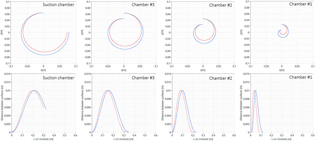
FIGURE 5. Distance between involutes along their length in their normal directions for one selected angle of orbit; normal to involute A (blue) and normal to involute B (red).
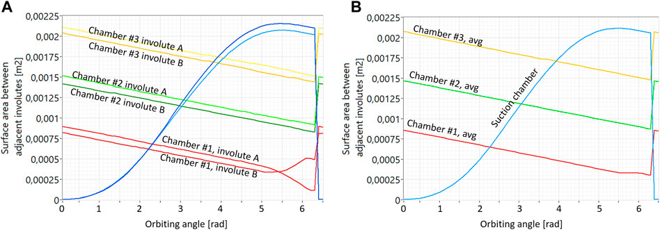
FIGURE 6. Integration of the distance in the normal direction from one involute is compensated with the integration error of distance in the normal direction from the other involute. Calculated surface area from the individual involutes is shown on left side (A) and average values are shown on the right side (B).
In numerical calculations of geometry, the resolution always affects the results. Typically, the results of numerical calculations approach the results of analytical solutions with the increasing resolution. The analysis of numerical calculations is shown in Figure 7. To evaluate the accuracy of numerical calculations, we used the calculation of the tangential/flank gap between the scrolls, depending on the angle of the orbit for different resolutions of the geometry, as shown in Figure 7A. The minimum gap value and the average gap value are shown in Figure 7B. As the resolution increases, the values converge. The calculation of the surface area of the suction chamber already converges at a resolution of 100 involute points per radian (Figure 7C). At an increased resolution due to the numerical nature of calculations, the surface area increases again and again, and converges at 400 points per radian to the solution, the same as with the resolution of 100 points per radian. It follows that at a resolution of 100 points per radian, we can estimate the volume of the suction chamber. With the same resolution, we can estimate the tangential/flank gap from the minimum value in the calculation series for all orbital angles.
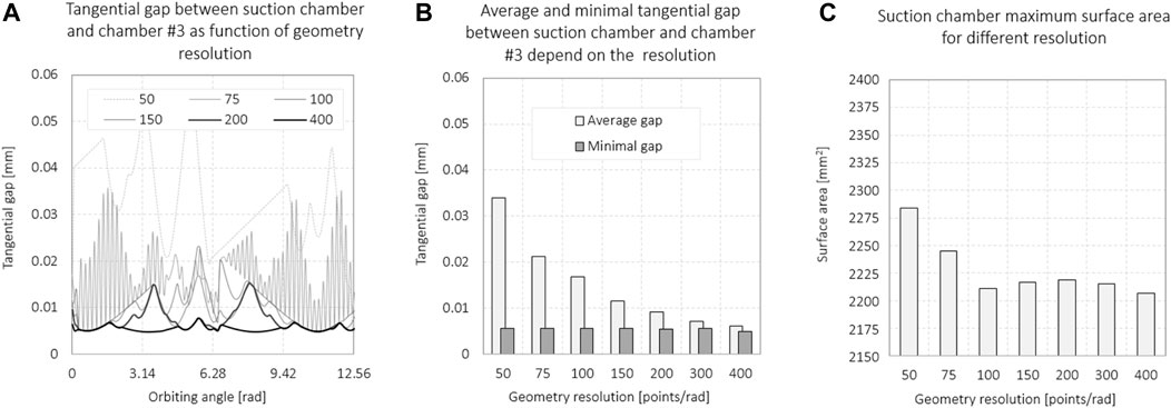
FIGURE 7. Influence of discretization on the estimated tangential/flank (A, B) gap and surface area (C) calculation. The resolution is given by the number of points in developing the involute for one radian.
3 Proposed method B
The calculation of chamber surfaces, as shown in method A, is based on an engineering approach, but unfortunately, we cannot prove that it is mathematically correct. To verify the reliability of the results of method A, we developed another numerical method B. In method B, the calculation of the chamber surfaces was performed by discretization into triangles. In method B, we only roughly estimate the position of the conjugate points. The method for evaluating the conjugate points aims specifically to evaluate the suction volume but it is also suitable for the evaluation of all chamber volumes.
3.1 Estimation of conjugate points
The conjugate points can be calculated analytically or estimated numerically for each orbiting angle. Method B is intended for quick calculations of the geometry of scroll compressors, so a simplification has been made. The conjugate point can be approximated to lie at the intersection of the orbiting angle line with the involutes, as shown in Figure 8. The error of such an estimate is negligible for the conjugate point defining the suction volume, which is farthest from the orbiting center (Figure 8A). Therefore, the calculation error of the compressor suction volume is negligible.
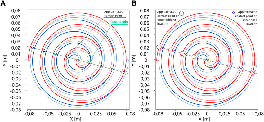
FIGURE 8. (A) Approximation of conjugate points and (B) only the pairs that overlap each other are the coincidence points.
Discrete points on the fixed and orbiting involute can be expressed with vectors pa and pb at a specific orbiting angle ϑ, as shown in in Eq. 16, where index a indicates the fixed involute, index b indicates the orbiting involute, I is the number of numerical points defining the fixed involute, and J is the number of numerical points defining the orbiting involute.
Assuming that all conjugate points lie on the same line and that the angle of this line coincides with the orbiting angle ϑ, the criterion for the elimination of discretional points (pa,i or pb,j) lying on the line can be defined for the fixed involute using Eq. 17:
and for orbiting involute using Eq. 18:
where
where N is the total number of identified points on the fixed involute and M is the total number of identified points on the orbiting involute. All the points lying at the intersections between the involute and the orbit angle line do not represent an approximation of the conjugate points between two involutes (Figure 8B). An additional elimination criterion must be applied. The Euclidian distance between each selected pair can be calculated to extract points from vectors pac and pbc, which represent the approximation of the conjugate points. Since involutes are discretized, the Euclidian distance is verified against the error value e, as shown in Eq. 20. Distances between conjugate points can be saved and then used in further thermodynamical models as the width of the tangential gap.
Pairs at which the criterion is met present approximate coincidence points and boundaries for obtaining the compression surface and can be written in the matrix form.
where L represents the total number of coincidence points between fixed and orbiting involutes.
3.2 Surface areas defined by two involutes and estimated conjugate points
Pairs of points from Pc, which approximate conjugate points, are used to define chamber surface areas and hence their working volume, as shown in Figure 9A. Selected compression areas are discretized in small triangles, and their vertices are neighboring points on the involute, as shown in Figure 9B. For each triangle with points A, B, and C, we can calculate the area using Eq. 22. Individual surfaces must be summed together at intervals defined with matrix Pc to obtain areas of different compression chambers.
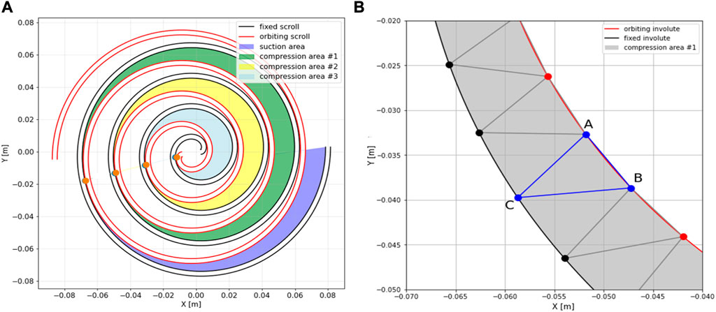
FIGURE 9. (A) Identified coincidence points and division of chambers inside the scroll compressor; (B) compression chamber discretization on triangles.
The number of points on the fixed and orbiting involutes is not equal; therefore, further simplification is needed. Figure 10 shows the differences between calculated surface areas when we shorten the interval of the longer involute to the number of points on the shorter involute. The results show a negligible error when integrating over two different involutes. We can also observe the dependence of the calculated area result on the number of points in the interval. The conclusion is that the difference is negligible if enough discrete points are chosen.
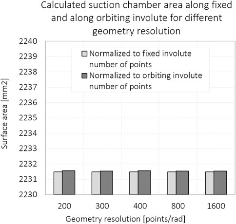
FIGURE 10. Calculated suction chamber areas along fixed and along orbiting involutes for different geometry resolutions.
The computation in the proposed method B is numerical and can easily handle discrete data with involute coordinates. The algorithm is fast and easy to understand and implement. After the fast and robust determination of the geometry of the compressing volumes, many described thermodynamic models can be used for parametric scroll compressor studies.
4 Discussion on numerical calculations of geometry
Two approximations are discussed as follows: 1) conjugate points lie on the intersection of the orbiting line with the involutes, and 2) the surface area between two conjugate involutes can be calculated using the distance in the direction of the normal vector from one involute to the other and the distance in the direction of the normal vector from the other involute back to the first involute. It is shown that the first approximation results in negligible errors in the calculation of the suction volume of the scroll compressor and that the results of the suction volume calculation by method A, which is based on the second approximation, are comparable with the results of method B. Moreover, the results of both methods are within 3% difference from the methods of Chen et al. (2002a), Wang et al. (2005), and Bell et al. (2012).
4.1 Conjugate points lie on the intersection of the orbiting line and involutes
The error caused by simplifying the location of the conjugate points, i.e., the integration limits, on the involute has been calculated. The location of the true conjugate point was defined by the minimum distance between two involutes, as shown in method A. Then, the intersection between the orbiting line and the involute was calculated using method B. The distance between the involutes in each chamber is shown in Figure 11 to demonstrate the error resulting from the approximation of method B. The mismatch between the true conjugate point and the approximated conjugate point is shown symbolically in Figures 8A and Figure 11. The plot in Figure 11 suggests that the suction volume calculated by method B is smaller than that calculated by method A, as expected. The error calculated by both methods for the volume of chambers #2 and #3 should be very similar since the integration interval is only shifted. The results are shown in Table 1. The error resulting from the simplification is given in angles [rad]. It is smaller for the conjugate points running out of the center of the orbit. The error for the last conjugate point defining the suction chamber is only 0.066 rad. Moreover, the distance between the involutes around the conjugate point is small, so the contribution to the integration of the chamber surface is small, as shown in Table 1.
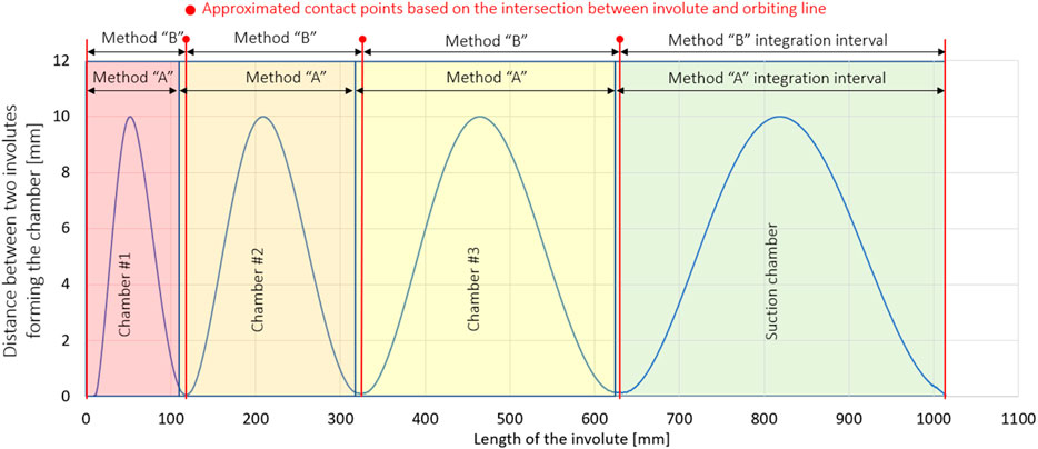
FIGURE 11. Distance between fixed and orbiting involutes along the length of the fixed involute, identified chambers usingminimal distance between involutes, and symbolic presentation of the integration intervals for the calculation of chamber surface areas using both methods A and B.
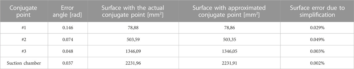
TABLE 1. Deviation of the coincidence point angle and calculated surface area of the working chamber obtained using methods A and B.
4.2 Validation of methods based on suction volume calculations
The design of compressors usually starts with the requirements for their delivery, i.e., mass flow at the inlet. The delivery capacity of the scroll compressor is determined primarily by the maximum size of the suction volume and the frequency; therefore, we compared the results of calculating the suction volume using methods A and B, both of which are based on a pure numerical approach, with the results of three analytical methods which represent fundamental works on calculating scroll geometry by Chen et al. (2002a), Wang et al. (2005), and Bell et al. (2012). Equation 9 in Chen’s work is slightly different from Eq. 16 in Wang’s work, resulting in a difference for the last part of the suction volume, where it starts to decrease. Equations 11 and 12 in Bell’s work are cumbersome, and errors occur easily. The results of calculating the suction volume for the three established methods and the proposed numerical methods are shown in Figure 12.
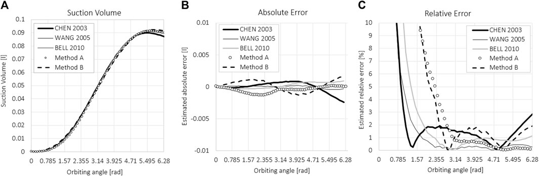
FIGURE 12. (A) Suction volume, (B) absolute error, and (C) relative error of the suction volume compared between five methods.
Figure 12A shows the suction volume as a function of the orbiting angle. The results are in good agreement. The average value of the calculated suction volume was used as a reference and compared with the results of the individual methods. For all five methods, the absolute and relative deviations of the obtained suction volume at a given orbital angle were calculated with respect to the mean value. The absolute deviation is shown in Figure 12B and is calculated as a subtraction from the mean value of all five methods. The relative deviation is calculated as the percentage error of the absolute error with respect to the average value and is shown in Figure 12C. The relative differences between the maximum suction volumes that determine the compressor delivery rate are calculated using five methods and are all within 3%. This result validates both numerical methods A and B for calculating the suction volume and thus allows an estimate of the delivery rate of the scroll compressor.
5 Measurement and modeling
Measurements were made on a 4-kW prototype of the oil-free scroll compressor with 4.55-mm-thick blades, as shown in Figure 13. The base radius of the scroll involute is 3.0 mm, with the starting angle of scroll involutes at ± 0.735 rad. The orbiting radius is 5.0 mm. The total length of the involutes is approximately 1 m, which results from an involute angle of 8π. The height of the scroll is 40 mm. The minimum gap size between scrolls, i.e., the location where tangential/flank leakage occurs, was estimated to be 0.002 mm, with the numerical calculation of scrolls with the same geometrical parameters. Two models for compressor delivery were tested. The first model is based on the hybrid modeling of the scroll compressor used in a micro-compressed air energy storage system, proposed by Ma et al. (2019). The second method is based on the numerically determined geometrical data obtained using method B and the thermodynamical equation of energy conservation.
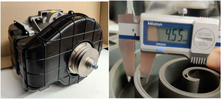
FIGURE 13. Omega Air scroll compressor prototype and geometry of the scrolls used in the experiment.
5.1 Measurement setup
Measurements of flow and pressure were made using the Omega Air portable data logger Omega Air OS 551-P6. The technical data on the pressure sensor and flow sensor are given in Table 2. The experimental setup was kept rudimentary to avoid complications, as shown in Figure 14. The experimental design was also kept simple, and only the filling of the pressure vessel from atmospheric pressure to 8 bar was measured at different speeds (500 RPM, 1000 RPM, 1500 RPM, 2000 RPM, 2500 RPM, and 2900 RPM). Pressure and mass flow on the suction and discharge sides were recorded. The results of the mass flow measured on the discharge side showed fluctuations and deviations, so they were not included in the results. The filling of the pressure vessel, i.e., the increase in pressure p2 in the vessel, is shown in Figure 15, together with the temperature of the compressed air at T2.
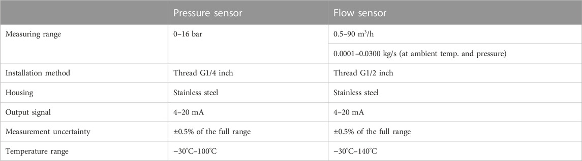
TABLE 2. Specifications of measurement equipment.
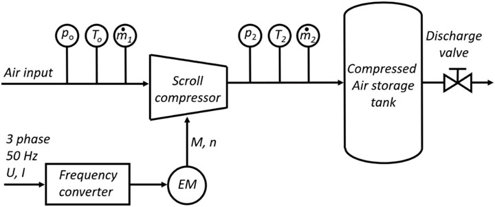
FIGURE 14. Experimental setup.
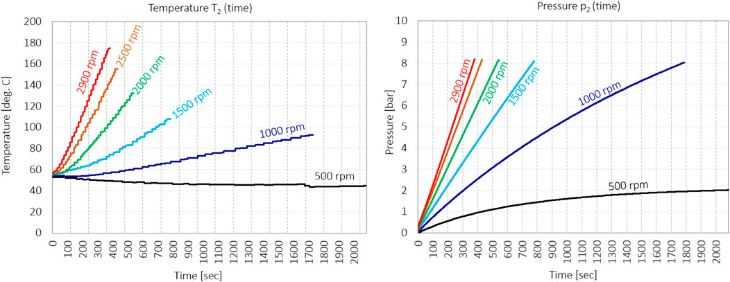
FIGURE 15. Pressure p2 and temperature T2 during pressurizing the vessel with different rotational speeds.
The experimental design was built around filling the pressure vessel with a total volume of 210 L, including the volume of the pipes. Before each run, the pressure chamber was relieved to ambient pressure. The compressor was started to fill the pressure chamber. At the beginning of each run, the temperature of the compressor was approximately 60°C as it was preheated from previous runs. The pressure buildup was measured for different rotational frequencies of the electric motor, as shown in Figure 15. From the results shown in Figure 15, it can be seen that the compressor does not reach the operating conditions when the rotation frequency is too low, i.e., below 500 RPM. When compressing air at a rotation frequency of 500 RPM, the compressor reaches a maximum pressure of only 2 bar. At a rotation frequency of 500 RPM, the air does not heat up to the typical operating temperature of 60°C at point T2 during compression so that the air temperature at the measuring point T2 drops to approximately 45°C. Only when the rotation frequency is increased to 1000 RPM, the compressor can reach a pressure of 8 bar and heat the air at point T2 above the typical temperature of the compressor.
5.2 Hybrid modeling of scroll compressors
Ma et al. (2019) presented a hybrid model of a scroll compressor. This method is based on the following assumptions: 1) an oil-free scroll compressor and clean gas are assumed; 2) an ideal gas is assumed, and the kinetic energy of the gas can be neglected; 3) the changes in temperature and pressure due to leakage in the same chamber can be neglected; and 4) the temperature and pressure losses due to internal leakage can be neglected as well. However, internal leakage is integrated into the overall volumetric losses together with the leakage of gas into the surrounding atmosphere. Based on the aforementioned assumptions, internal compression is considered an ideal adiabatic process. Although the over and underpressure processes are considered, this model can neither directly reflect the relationship between the output and compressor speed, back pressure, and other conditions nor can it reflect the distinction between different compressor types.
The model assumes that a scroll compressor operates as a volumetric machine, where the ideal flow rate is defined by the behavior of the suction volume with the rotational frequency. In this model, all leakages are described integrally with a quadratic pressure function, leading to equation Eq. 23, which models the mass flow:
where pB is the discharge pressure and ω is the rotation frequency. Constants A, B, and C depend on the specific design of the scroll compressor, but their values can be estimated using Eqs 24–26.
where
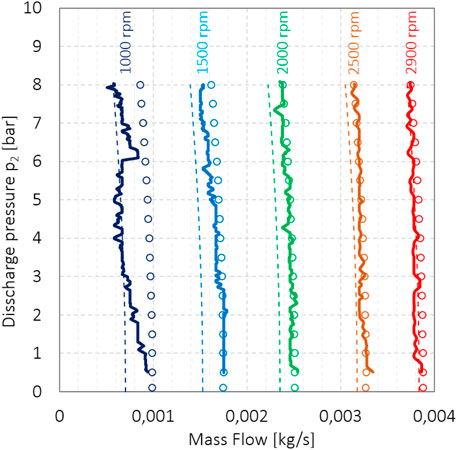
FIGURE 16. Measured compressor delivery (thick lines), result of the original hybrid model provided by Ma et al. (thin dashed line), and the modified hybrid model taking into account the volumetric suction rate
The original model ignores the influence of the heating of the intake air in the suction volume and the influence of the underpressure in the suction volume. The mass of the actually sucked volume of gas is smaller than that of the geometrically calculated suction volume. We can then easily introduce a volumetric suction rate ψ into the model to compensate for this. Based on the assessment of the heating of the inlet air and the vacuum, we can estimate the volumetric suction rate ψ to be 0.92. With its introduction, the mass flow compensation predicted by Ma et al. decreases from 0.00095 to 0.00053, i.e., by 45%. It should be noted that the equation for coefficient C as given in the article by Ma et al. has reversed signs. With these modifications, we obtained the results, as shown in Figure 16, in the form of points. We observed that the results obtained according to the modified equations (Eqs 27 and 28) for B’ and C’ agree better with the measurements, resulting in the smaller compensating term qcomp. Figure 16 shows modifications that account for intake air heating and negative pressure in the intake volume, and contribute to the accuracy of the model as predicted results have better agreement with measurements than predicted values from the original model.
5.3 Compressor delivery modeling based on numerical calculations of geometry
In this work, we are primarily interested in the delivery of a scroll compressor and not in its efficiency; therefore, only leakage is considered in a presented simplified delivery model. The input of the simplified delivery model calculation is based on the results from the numerical calculations of geometry using the proposed method B. The presented model is based on the iterative calculation of multiple thermodynamic variables inside the chambers of scroll compressors. Such models already exist in Bell (2011), but expanding them to access delivery with respect to discharge pressure was not observed. Results of this simplified model are compared with the results of the hybrid model for a small scroll compressor proposed by Ma et al. (2019). Finally, the results of modeling are compared with measurements.
The simplified delivery model is based on the conservation of energy and mass and on the equation of the gas state. The working fluid in each individual chamber of the scroll compressor is treated like the 0D thermodynamic domain. According to the first law of thermodynamics, the energy equation for the working fluid during compression is established. Considering the moving working fluid, the mass flow in and out of the domain, the ideal gas assumption, and the derivation of the temperature with respect to the turning angle of an orbiting scroll wrap, conservation of energy can be written for the working fluid (Bell, 2011) as
where T is the temperature of the working fluid, ρ is its density, ϑ is the orbiting angle, R is the specific gas constant, V is the volume, v is the specific volume, mCV is the mass of the fluid in the working chamber, h is the enthalpy,
The state equation of gas is used to calculate pressure:
The source of the significant decrease in the volumetric efficiency comes from two types of leakage that can be identified in a scroll compressor. Tangential or flank leakage comes from the gap between the inner and outer scroll wraps among two neighboring chambers, and radial leakage is formed by the gap between fixed and orbiting scrolls. Both types are shown in Figure 17. Basically, four modeling approaches for estimating leakage in scroll compressors are reported in the literature: i) the isentropic flow model; ii) the incompressible viscous flow model; iii) the adiabatic compressible viscous flow model (the Fanno flow model); and iv) the quasi-one-dimensional model (Evandro et al., 2020). In this paper, the mass flow rate through the described gaps is calculated using equations for the isentropic-flow model of compressible gas through the nozzle. From Fox et al. (2020), the equation is corrected by flow factor f.
where A is the cross-sectional area of the leakage gap, Ph and Pl are values of pressure on high- and low-pressure sides, respectively,
where

FIGURE 17. Tangential/flank gap (A) and radial gap (B) as sources for leakage.
The input data for the simplified delivery model are the volumes of suction, compression, and discharge chambers as functions of the orbital angle ϑ. All volumes are calculated using the proposed method B. In our case, suction and three compression chambers are modeled simultaneously. One revolution of the orbiting scroll is discretized in small steps, and new values of gas properties are calculated in each step. In the first step, the initial values of temperature, pressure, mass, and density are calculated for each chamber assuming adiabatic compression without heat transfer and leakage. Then, the mass flow due to tangential and radial leakages between the chambers is estimated using Eq. 32 from the atmosphere and discharge vessel.
The mass conservation equation (Eq. 30) is used to calculate new values of mass of the gas inside the specific chamber at the next step.
where i is the time instant.
At the end, the pressure is calculated using ideal gas assumption (Eq. 31). The described procedure is repeated for every discrete angle. Due to the assumption of adiabatic compression for modeling a real process, discontinuities in temperature and pressure curves occur during the first iteration; therefore, more iterations are needed, until reaching the threshold error value. Relaxation is advised when transferring values between iterations.
To model the change in mass flow through the scroll compressor as a function of discharge pressure, i.e., in the pressure vessel, the discharge pressure was varied from the atmospheric pressure to a value of 8 bar, simulating the pressure buildup in the vessel. The calculated mass of the gas at the outlet was multiplied by the rotational speed of the compressor. The results of the simulations are shown in Figure 18 using a thin line, and the measurement results are shown using a thick line. Simplicity and efficient calculation are the flagship of the presented model, and we must take into account that the assumptions made may affect the accuracy of the results. The 0D model assumes the uniform pressure and temperature field in the chambers of the scroll compressor; the heat transfer between the chambers and the environment is selected and could be taken into account in further investigations. Moreover, the numerical nature and time discretization may have a great impact on the results, so sufficiently small time steps are required.
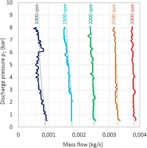
FIGURE 18. Simulations of mass flow through the scroll compressor, obtained using the simplified delivery model and numerically obtained geometry data (thin lines), and measured mass flow of the scroll compressor (thick line).
A comparison of the results of the delivery of the spiral compressor according to the two methods is shown in Figure 19. The mass flow rate is normalized for rotation frequency; therefore, the mass flow is given for one rotation of the scroll. Under ideal conditions, the mass flow to the compressor, normalized to one revolution, should be equal to the suction volume and should be independent of discharge pressure and rotation frequency. The black line represents the ideal mass flow rate. Under ideal conditions, the intake volume is filled with fresh gas; it does not heat up, and since there are no leaks, no gas enters the suction volume from the adjacent chambers where the pressure is already increased. Due to the heating of the inlet air and due to air leakage from the adjacent chambers, the mass flow decreases with revolutions and with pressure. The results obtained according to Ma’s model, which was upgraded for the volumetric suction rate ψ, are shown with circles. Results of the simplified delivery model, based on numerically calculated geometry, are shown using thin lines. The figure shows how both models predict the change in mass flow with discharge pressure. The difference between the hybrid model and the presented model based on numerical geometric analyses is minimal for revolutions from 2900 RPM to 2000 RPM. At revolutions of 1500 RPM, the difference is already significant, and from the comparison of the modeling results with the measurement results (Figures 16, 19), we can say that the simplified delivery model based on the numerical calculation of the geometry model sufficiently describes the delivery of the scroll compressor for the wide operational range. At 1/3 of the nominal revolutions, the deviation according to Ma’s model is already large (Figure 16), while our model clearly describes what happens in the compressor (Figure 19).
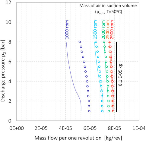
FIGURE 19. Correlation between the mass flow delivery (normalized per revolution at the compressor inlet) and the discharge pressure, according to Ma’s model (circles) and according to the simplified delivery model (thin line).
If we consider the mass flow normalized to one revolution as a function of rotational frequency, we observe that as the rotational frequency decreases, the normalized mass flow also decreases, as shown in Figure 20. This is consistent with expectations as volumetric losses are typically higher at lower rotational speeds, which is also predicted by Ma’s model. The simplified delivery model and Ma’s model describe well the delivery performance of the scroll compressor at different discharge pressures and at higher rotational frequencies. The simplified delivery model, on the other hand, better describes the volumetric losses when the rotation frequency decreases.
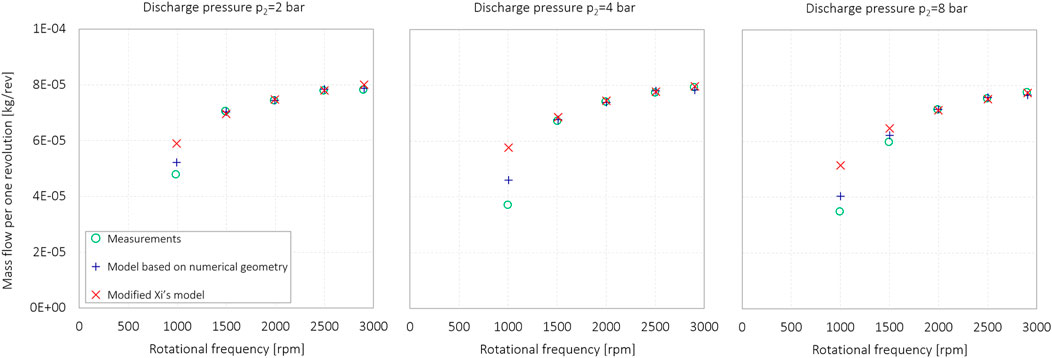
FIGURE 20. Measured and modeled mass flow, normalized to one revolution, as a function of the rotational frequency for discharge pressures 2 bar, 4 bar, and 8 bar.
As observed, leakage contributes significantly to the overall performance and efficiency of scroll compressors. The leakage is directly related to the tangential and radial gaps, so its accurate calculation in the models is essential for a good prediction of the compressor performance. Using efficient resolutions, the proposed methods A and B provide accurate determination of the tangential gap compared to analytical approaches. We must emphasize here that the comparison with real compressors is difficult due to the small values of the gaps, the inaccessibility of the gap to measure it, the lack of information from scroll compressor manufacturers, and the changing gap size under real operating conditions due to poor air quality (air contaminants).
6 Conclusion
In this paper, two new methods for a purely numerical calculation of the chamber surface area in a scroll compressor have been developed to make the process of the scroll compressor design, investigation, and evaluation faster, easier, and more understandable. Both methods consist of two steps. The first step is to determine the conjugate points, and the second step is to calculate the working surface area of the chamber as a function of the orbital angle.
The first method is based on the numerical identification of the conjugate point with the smallest distance between the fixed and the orbiting scroll. The chamber volumes are then calculated by integrating the partial areas defined by the normal distances between the two curves and multiplying by the height of the scroll. It is shown that discretization of scrolls with a resolution of 400 points per radian provides accurate results with an estimated maximum error of 3%, which includes the uncertainty/error of three proposed methods based on analytical calculations and two proposed numerical methods.
The second method simplifies the calculation of the conjugate points and sets them to the intersection of the orbiting angle line with the involutes. This simplification introduces an error, but the numerical approach limits the total error, which ends up being negligible. The chamber surfaces defined by two involutes and the pair of their conjugate points are then discretized into triangles. The surface integration of the triangles describes the surface area of the chamber. The difference between the number of points describing the inner and outer involutes has no significant effect on the calculation of the chamber surface, and the error is negligible for engineering use.
The results of the two proposed methods were compared with three analytical models to justify all assumptions and simplifications. The relative differences between the maximum suction volumes that determine the compressor delivery rate are calculated using five methods and are all within 3%. This result validates both numerical methods A and B for the calculation of the suction volume, thus allowing an estimation of the delivery rate of the scroll compressor. The main advantage of the proposed methods is that the numerically obtained results of the geometry can be easily implemented in thermodynamic models to simulate the behavior of scroll compressors.
Finally, the results of the simplified delivery model were calculated and compared with the results of the hybrid model proposed by Ma et al. and with measurements of the scroll compressor at different rotational frequencies and discharge pressures. Ma’s hybrid method was slightly improved for the mass flow rate. The results of the simplified delivery model agree with the measurement results in the pressure range from 1 bar to 8 bar, and in the rotational frequency range, the results range from 1000 RPM to 3000 RPM.
Thus, we have proved that the proposed methods for the numerical calculation of geometry can be applied to scroll compressors and are useful for the study and design of these machines. A similar approach can be used for other types of compressors, such as scroll compressors and Z-compressors. Methods enable simple implementation, further development, and upgrading, especially in terms of heat transfer. They can be further used in studies on compressed air storage systems (CAES), air conditioning, heat pumps, and fuel cells.
Data availability statement
The raw data supporting the conclusion of this article will be made available by the authors, without undue reservation.
Author contributions
JP: original draft, method A, and experimental part; NC: method B and the method for compressor modeling. All authors contributed to the article and approved the submitted version.
Conflict of interest
The authors declare that the research was conducted in the absence of any commercial or financial relationships that could be construed as a potential conflict of interest.
Publisher’s note
All claims expressed in this article are solely those of the authors and do not necessarily represent those of their affiliated organizations, or those of the publisher, the editors, and the reviewers. Any product that may be evaluated in this article, or claim that may be made by its manufacturer, is not guaranteed or endorsed by the publisher.
References
Bell, I. H., Groll, E. A., Braun, J. E., and King, G. B. (2010). Update on scroll compressor chamber geometry. Proc. Int. Compress. Eng. Conf. 1489, 1–8.
Bell, I. H., Groll, E. A., Braun, J. E., Horton, W. T., and Lemort, V. (2014). Comprehensive analytic solutions for the geometry of symmetric constant-wall-thickness scroll machines. Int. J. Refrig. 45, 223–242. doi:10.1016/j.ijrefrig.2014.05.029
Bell, I. H., Lemort, V., Groll, E. A., Braun, J. E., King, G. B., and Horton, W. T. (2012). Liquid-flooded compression and expansion in scroll machines - Part I: model development. Int. J. Refrig. 35 (7), 1878–1889. doi:10.1016/j.ijrefrig.2012.07.010
Bell, I. H. (2011). Theoretical and Experimental analysis of liquid flooded compression in scroll compressors, doctoral dissertation. Indiana: Purdue University.
Chen, Y., Halm, N. P., Braun, J. E., and Groll, E. A. (2002b). Mathematical modeling of scroll compressors — Part II: overall scroll compressor modeling. Int. J. Refrig. 25, 751–764. doi:10.1016/s0140-7007(01)00072-x
Chen, Y., Halm, N. P., Groll, E. A., and Braun, J. E. (2002a). Mathematical modeling of scroll compressors—part I: compression process modeling. Int. J. Refrig. 25, 731–750. doi:10.1016/s0140-7007(01)00071-8
Cordone, M., and Gargiulo, B. (2020). Numerical simulation and experimental validation of an oil free scroll compressor. Energies 13, 5863. doi:10.3390/en13225863
Ding, J., Yue, X., Zhang, Y., and Ba, D. (2021). Accurate calculations of working chamber volume constructed from involute of variable radii circle with double arcs modification in a scroll type compressor. Proc. Institution Mech. Eng. Part E J. Process Mech. Eng. 235 (5), 1652–1664. doi:10.1177/09544089211013661
Dumont, O., Parthoens, A., Dickes, R., and Lemort, V. (2018). Experimental investigation and optimal performance assessment of four volumetric expanders (scroll, screw, piston and roots) tested in a small-scale organic Rankine cycle system. Energy 165, 1119–1127. doi:10.1016/j.energy.2018.06.182
Evandro, L., Pereira, L., and Deschamps, C. J. (2020). Numerical analysis and correlations for radial and tangential leakage of gas in scroll compressors. Int. J. Refrig. 110, 239–247. doi:10.1016/j.ijrefrig.2019.11.002
Fanti, G. R., Romao, D. A., de Almeida, R. B., and Batista de Mello, P. E. (2020). Influence of flank clearance on the performance of a scroll expander prototype. Energy 193, 116823. doi:10.1016/j.energy.2019.116823
Fox, R. W., McDonald, A. T., and Mitchell, J. W. (2020). Fox and McDonald`s introduction to fluid mechanics. Hoboken, NJ, United States: John Wiley & Sons, Inc.
Ishii, N., Sakai, M., Sano, K., Yamamoto, S., and Otokura, T. “A fundamental optimum design for high mechanical and volumetric efficiency of compact scroll compressors,” in Proceedings of the International Compressor Engineering Conference, Purdue, IN, USA, July 1996, 1176.
Lee, Y. R., and Wu, W. F. (1995). On the profile design of a scroll compressor. Int. J. Refrig. 18, 308–317. doi:10.1016/0140-7007(95)00013-2
Ma, X., Zhang, C., and Li, K. (2019). Hybrid modeling and efficiency analysis of the scroll compressor used in micro compressed air energy storage system. Appl. Therm. Eng. 161, 114139. doi:10.1016/j.applthermaleng.2019.114139
Mendoza, L. C., Lemofouet, S., and Schiffmann, J. (2017). Testing and modelling of a novel oil free corotating scroll machine with water injection. Appl. Energy 185, 201–213. doi:10.1016/j.apenergy.2016.10.089
Mojiri, A., Mikel, M., and Barber, T. (2020a). Compression chamber volume analysis for co-rotating scroll compressors. Int. J. Refrig. 112, 172–188. doi:10.1016/j.ijrefrig.2020.01.005
Mojiri, A., Mikel, M., and Barber, T. (2020b). Compression chamber volume analysis for co-rotating scroll compressors. Int. J. Refrig. 112, 172–188. doi:10.1016/j.ijrefrig.2020.01.005
Mojiri, A., Mikel, M., and Barber, T. (2019). Geometry of wrap profiles in co-rotating scroll compressors. Int. J. Refrig. 106, 327–337. doi:10.1016/j.ijrefrig.2019.06.032
Pereira, E. L. L., and Deschamps, C. J. (2017). A heat transfer correlation for the suction and compression chambers of scroll compressors. Int. J. Refrig. 82, 325–334. doi:10.1016/j.ijrefrig.2017.05.033
Qiang, J., and Liu, Z. (2013). Scroll profiles in scroll compressors: general criteria and error sensitivity. Int. J. Refrig. 36, 1796–1808. doi:10.1016/j.ijrefrig.2013.09.030
Rak, J., and Pietrowicz, S. (2020). Internal flow field and heat transfer investigation inside the working chamber of a scroll compressor. Energy 202, 117700. doi:10.1016/j.energy.2020.117700
Shaffer, B. R., and Groll, E. A. (2013). Variable wall thickness scroll geometry modeling with use of a control volume approach. Int. J. Refrig. 36, 1809–1820. doi:10.1016/j.ijrefrig.2013.08.003
Shuaihui, S., YuanYang, Z., Pengcheng, S., and Shu, P. (2010). Simulation research on scroll refrigeration compressor with external cooling. Int. J. Refrig. 33, 897–906. doi:10.1016/j.ijrefrig.2010.03.005
Sun, S., Wang, X., Guo, P., and Song, Z. (2020). Investigation on the modifications of the suction flow passage in a scroll refrigeration compressor. Appl. Therm. Eng. 170, 115031. doi:10.1016/j.applthermaleng.2020.115031
Wang, B., Li, X., and Shi, W. (2005). A general geometrical model of scroll compressors based on discretional initial angles of involute. Int. J. Refrig. 28 (6), 958–966. doi:10.1016/j.ijrefrig.2005.01.015
Wang, C., Zhang, S., Lei, B., Cheng, J., and Wu, J. (2022b). Analysis on influence factors of back pressure in an asymmetrical algebraic scroll compressor. Int. J. Refrig. 138, 97–107. doi:10.1016/j.ijrefrig.2022.03.011
Wang, C., Zhang, S., Zhao, Z., Cheng, J., and Wu, J. (2023). Study on the contact and size of radial and flank leakage gaps of scrolls in a scroll compressor with CFD/CSM simulations. Int. J. Refrig. 149, 73–82. doi:10.1016/j.ijrefrig.2022.11.030
Wang, J., Dong, L., XI, Z., Cao, C., and Wang, Z. (2021a). Construction and simulation of novel asymmetrical scroll wraps for scroll vacuum pumps. Vacuum 183, 109837. doi:10.1016/j.vacuum.2020.109837
Wang, J., Dong, L., Xi, Z., Cao, C., and Wang, Z. (2021b). Construction and simulation of novel asymmetrical scroll wraps for scroll vacuum pumps. Vacuum 183, 109837. doi:10.1016/j.vacuum.2020.109837
Wang, J., Han, Y., Pan, S., Wang, Z., Cui, D., and Geng, M. (2022a). Design and development of an oil-free double-scroll air compressor used in a PEM fuel cell system. Renew. Energy 199, 840–851. doi:10.1016/j.renene.2022.08.154
Winandy, E., Claudio, S. O., and Lebrun, J. (2002). Experimental analysis and simplified modelling of a hermetic scroll refrigeration compressor. Appl. Therm. Eng. 22, 107–120. doi:10.1016/s1359-4311(01)00083-7
Xudong, W., Yunho, H., and Reinhard, R. (2008). Investigation of potential benefits of compressor cooling. Appl. Therm. Eng. 28, 1791–1797. doi:10.1016/j.applthermaleng.2007.11.010
Zhang, X., Zhang, B., Cao, J., Su, L., and Li, K. (2022). Numerical investigation on the performance and vapor injection process of a scroll compressor with different injection features. Appl. Therm. Eng. 217, 119061. doi:10.1016/j.applthermaleng.2022.119061
Ziviani, D., Bell, I. H., Zhang, X., Lemort, V., De Paepe, M., Braun, J. E., et al. (2020). PDSim: demonstrating the capabilities of an open-source simulation framework for positive displacement compressors and expanders. Int. J. Refrig. 110, 323–339. doi:10.1016/j.ijrefrig.2019.10.015
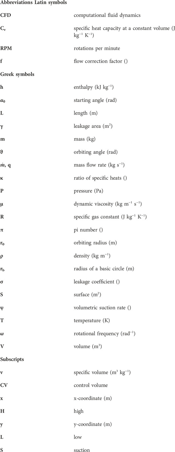
Nomenclature
Keywords: scroll compressor, involute pair, numerical calculation of geometry, suction volume, delivery of the scroll compressor, tangential or flank gap
Citation: Prezelj J and Cerkovnik N (2023) Numerical calculation of scroll compressor geometry and assessment of its delivery. Front. Mech. Eng 9:1226857. doi: 10.3389/fmech.2023.1226857
Received: 22 May 2023; Accepted: 10 August 2023;
Published: 01 September 2023.
Edited by:
Tabish Alam, Central Building Research Institute (CSIR), IndiaReviewed by:
Pablo Olmeda, Polytechnic University of Valencia, SpainMd Irfanul Haque Siddiqui, King Saud University, Saudi Arabia
Copyright © 2023 Prezelj and Cerkovnik. This is an open-access article distributed under the terms of the Creative Commons Attribution License (CC BY). The use, distribution or reproduction in other forums is permitted, provided the original author(s) and the copyright owner(s) are credited and that the original publication in this journal is cited, in accordance with accepted academic practice. No use, distribution or reproduction is permitted which does not comply with these terms.
*Correspondence: Nejc Cerkovnik, bmVqYy5jZXJrb3ZuaWtAZnMudW5pLWxqLnNp