 Gustavo Koury Costa
 Nariman Sepehri
- 1Department of Mechanical Engineering, Federal Institute of Science and Technology of the State of Pernambuco, Recife, Brazil
- 2Department of Mechanical Engineering, University of Manitoba, Winnipeg, Manitoba, Canada
Hydraulic accumulators have long been used in hydraulic circuits. Applications vary from keeping the pressure within a circuit branch to saving load energy. Among these applications, storing and releasing energy has gained attention in recent years due to the need for efficient circuits. In this sense, accumulators are the hydraulic counterparts of batteries and capacitors in electrical circuits. From hydraulic hybrid vehicles to complex agricultural machinery, accumulators have been successfully implemented, and significant energetic gains have been reported. This article reviews typical applications where accumulators can be used to this end and discusses the challenges that still have to be overcome in each situation.
1 Introduction
Hydraulic accumulators are the fluid equivalent of electrical capacitors (Yudell and Van de Ven, 2017; Leon-Quiroga et al., 2020). As such, they have been used to store energy. Their applications include hybrid vehicles (Costa and Sepehri, 2015; U.S. Environmental Protection Agency, 2020; Pourmovahed et al., 1992; Deppen et al., 2012; Deppen et al., 2015; Beachley et al., 1983; Ho and Ahn, 2010; Chapp, 2004; Chen et al., 2022; Sprengel and Ivantysynova, 2013), wind and wave energy extraction (Dutta et al., 2014; Fan et al., 2016a; Fan et al., 2016b; Fan et al., 2016c; Irizar and Andreasen, 2017; Fan and Mu, 2020), excavators and machinery alike (Heybroek et al., 2012; Lin and Wang, 2012; Shen et al., 2013; Hippalgaonkar and Ivantysynova, 2016a; Hippalgaonkar and Ivantysynova, 2016b; Ren et al., 2018; Yu and Ahn, 2020; Bertolin and Vacca, 2021). Accumulators have also been used as low-pressure tanks in closed hydraulic circuits (Çalışkan et al., 2015; Costa and Sepehri, 2019), shock absorbers (Porumamilla et al., 2008), and as part of switched hydraulic circuits, where hydraulic power at the actuator is controlled by fast-switching hydraulic valves instead of spool valves (to reduce throttling losses) (Brown et al., 1988; De Negri et al., 2014; Kogler and Scheidl, 2016; Yudell and Van de Ven, 2017).
With respect to their constructive type, accumulators are categorized into gas-loaded, weight-loaded, and spring-loaded types (Costa and Sepehri, 2015). Gas-loaded (hydropneumatic) accumulators are the most commonly used in hydraulic circuits, being evidenced in all references quoted so far, and are the focus of this article. However, it is important to say something about weight- and spring-loaded accumulators before we continue.
Weight-loaded accumulators provide a (nearly) constant pressure during discharge since they store potential gravitational energy within a vertically moving mass, as illustrated in Figure 1.
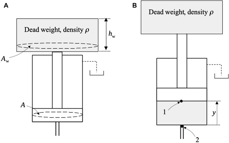
FIGURE 1. Weight-loaded accumulator: (A) uncharged and (B) charged.
Particularly, the output static pressure at point 2 (Figure 1B) depends on the elevation height,
Figure 2A shows the schematic representation of a spring-loaded accumulator. As hydraulic oil enters, the spring is compressed and the piston moves upward at distance
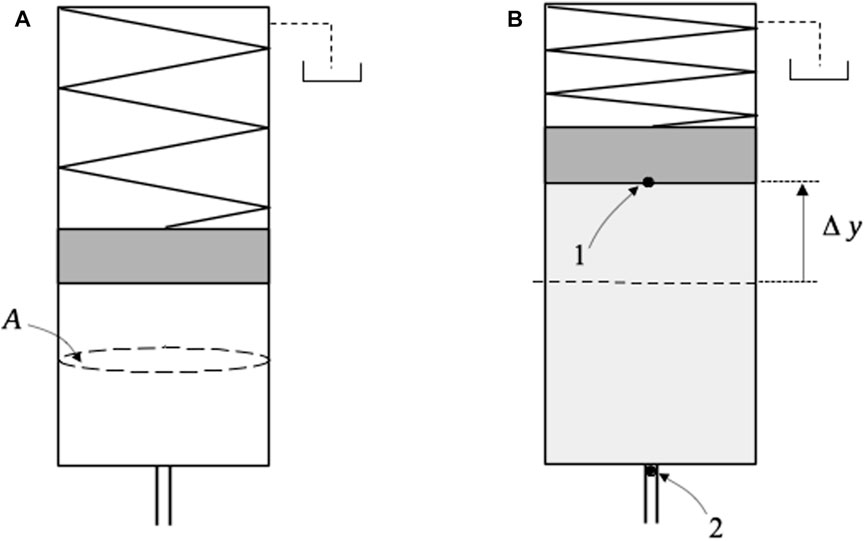
FIGURE 2. Spring-loaded accumulator: (A) uncharged and (B) charged.
The most common type of hydraulic accumulator is the gas-loaded accumulator. Typically, gas-loaded accumulators have a gas chamber separated from the oil by a bladder or diaphragm, with the great advantage of not having moving elements and, consequently, leaks. Piston-type gas accumulators also exist (Pfeffer et al., 2016), but there is an inherent leakage risk as well as the added inertia of the moving separator (piston). Figure 3 illustrates the three types of gas-loaded accumulators.
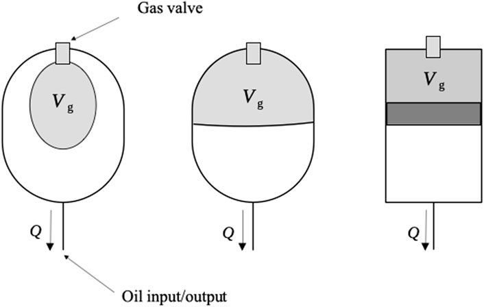
FIGURE 3. Gas-loaded accumulator types: (from left to right) bladder, diaphragm, and piston accumulators.
By far, gas-loaded accumulators are the most used in hydraulic circuits. A comparison between the accumulator types is given in Table 1.
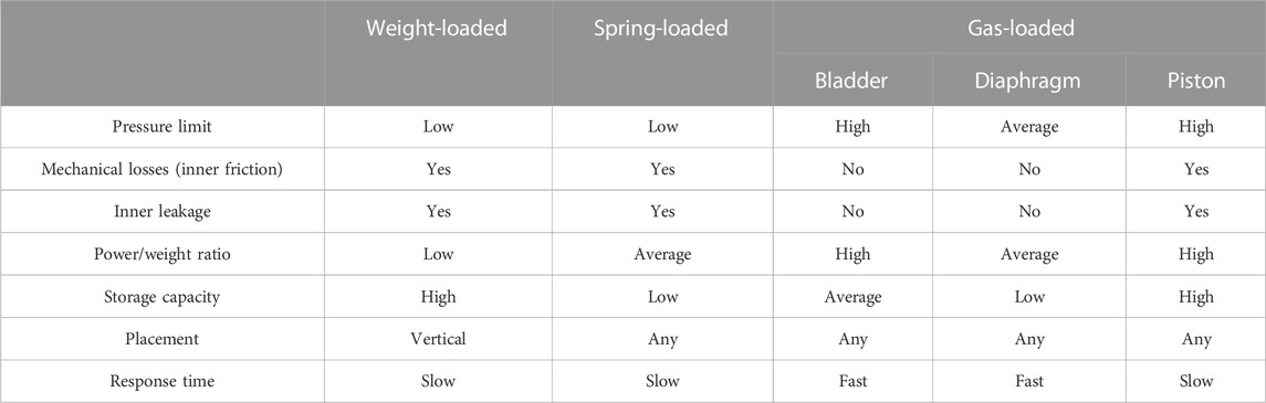
TABLE 1. Brief relative comparison between weight-, spring-, and gas-loaded accumulators.
In Section 2, we present a brief mathematical analysis of gas-loaded accumulators.
2 Mathematical modeling of gas-loaded accumulators
Considering that the accumulators illustrated in Figure 3 are isothermally loaded, the simplest relationship between the input pressure and the gas chamber volume can be obtained from the perfect gas law.
where
In Eq. 1, we have considered that the accumulator gas is ideal and that the heat transfer between the accumulator and the environment guarantees an isothermal process. In many situations, the resulting simplified model (1) is adequate to simulate an actual scenario (Dutta et al., 2014; Fan et al., 2016a; Pfeffer et al., 2016). However, a more general approach consists in treating the charging/discharging process as lying somewhere between isothermal and adiabatic and using the polytropic relation
The input/output oil flow,
where
Equations 2, 3 can be solved for some particular situations. For instance, consider the case where the accumulator is discharged into a tank at pressure
where
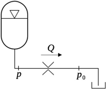
FIGURE 4. Accumulator discharging to tank through a fixed orifice.
Equation 4 can be integrated by making
From Eq. 6, we obtain the pressure within the gas chamber as a function of time
Equation 7 has a practical implication. If a gas-loaded accumulator is used to drive an actuator, both flow and force change in time. The only possible way of keeping a constant pressure,
As a general rule, pressure control in gas-loaded accumulators is carried out through a variable orifice, where
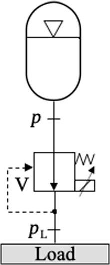
FIGURE 5. Pressure control using a piloted pressure-reducing valve.
A novel way of providing a constant pressure output was proposed by Van de Ven (2013). The idea was to modify the accumulator such that the gas would act on a variable piston area,
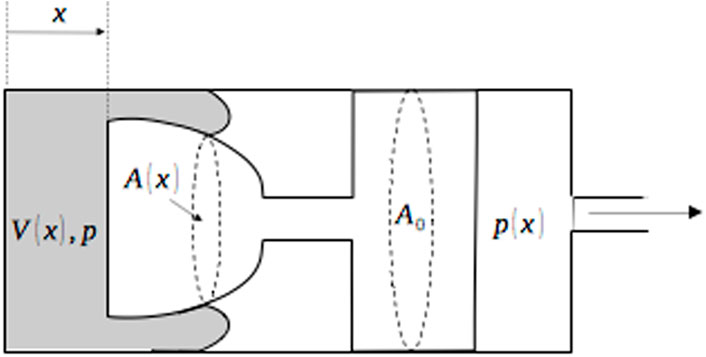
FIGURE 6. Constant pressure gas-loaded accumulator (Van de Ven, 2013).
For the simplest scenario, when the perfect gas law is applied to an isothermal process and dynamic forces are disregarded,
The solution proposed by Van de Ven (2013) adds a moving mass to the accumulator, and although dynamic forces are not considered in Eq. 8, they might play an important role in transient behavior.
Another approach to the variable-pressure problem consists in changing the compressed gas volume,
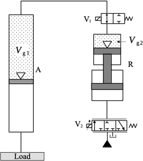
FIGURE 7. Variable gas volume accumulator (Liu et al., 2020).
Other concepts have been suggested that allow for controlling the output pressure. For instance, Zhao et al. (2019) introduces a piston-type gas accumulator where the variable pressure at the accumulator output is counterbalanced by a mechanical device attached to the piston. The resulting design (not shown here) is relatively complex and involves a cam mechanism together with roller bearings.
In the following sections, we describe typical uses of gas-loaded accumulators in hydraulic circuits as energy storage components.
3 Energy storage and reuse from multiple actuators
In many situations, accumulators can be used to store energy during motoring quadrants, i.e., when energy flows from the load into the hydraulic circuit. In one case scenario, accumulators can store energy from several hydraulic actuators and/or motors through a common pressure rail (CPR) system. To illustrate the CPR concept, the circuit shown in Figure 8 is considered. In the figure, we observe a high-pressure accumulator, H, and a low-pressure accumulator, L. The pressure differential between accumulators H and L provides the driving force for cylinders A and B, which move against resistive loads,
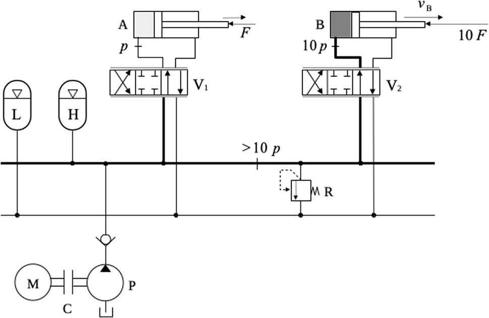
FIGURE 8. Common pressure rail (CPR).
CPRs can be considerably improved through the substitution of directional valves with hydraulic transformers, where throttling losses are not an issue (Shen et al., 2013). In fact, the design evolution of hydraulic transformers has recently drawn the attention of heavy machine manufacturers to the use of CPRs as a means of increasing the energetic performance (Heybroek et al., 2012).
It is possible to use accumulators to store load energy even when one single actuator is present, as shown in Figure 9.
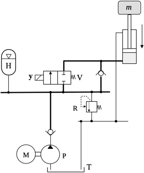
FIGURE 9. Hydraulic circuit with one actuator (CPR-style design).
In Figure 9, the low-pressure accumulator has been replaced by the tank. The cylinder lifts a load of mass
Valve-controlled actuators are accompanied by losses at the cylinder control valve. This is the case even when there is no flow reduction, as in Figure 9, where no velocity control is required for the cylinder. More energy efficient circuits eliminate cylinder control valves altogether, where stored energy is not dissipated into heat. Circuits such as these are denominated pump-controlled actuators [or “hydrostatic actuators” (Costa and Sepehri, 2015)] and are a direct evolution from “hydrostatic transmissions,” where a hydraulic motor is directly connected to the pump. We deal with hydrostatic transmissions and actuators in Section 4.
4 Energy storage and reuse in hydrostatic transmissions and actuators
There are two ways how we can use an accumulator to store energy from the load in a hydrostatic transmission or actuator. The first way is by connecting the high- and low-pressure accumulators directly to the main hydraulic circuit. The second way is by creating a secondary circuit with its own pump/motor where the accumulators are placed. Figure 10 shows two application examples.
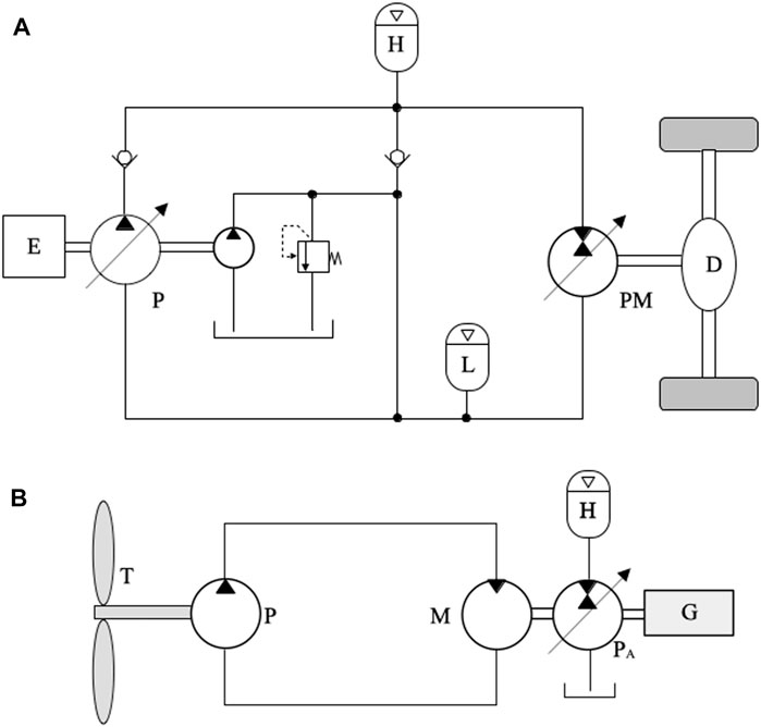
FIGURE 10. (A) Inline accumulators in a hybrid automobile transmission [reproduced from Costa and Sepehri (2015)] and (B) secondary accumulator circuit in a wind generator [reproduced from Dutta et al. (2014)].
Figure 10A shows the circuit for a hydraulic hybrid automobile (Costa and Sepehri, 2015). The engine, E, supplies energy to the wheels through pump, P, connected to the pump/motor, PM, which drives the differential, D. This is a fairly simple circuit, and many improvements have been made through the years (U.S. Environmental Protection Agency, 2020; Deppen et al., 2012; Ho and Ahn, 2010; Sprengel and Ivantysynova, 2013). The accumulator H is charged whenever energy flows from D to PM or when the automobile is idle, while the engine is still running. In both cases, energy that would otherwise be wasted is stored in H.
One clear disadvantage of placing the accumulator in parallel to the main hydraulic circuit is that the effective bulk modulus of the system is drastically reduced. In the particular case of an automobile, the effect is a “spongy” feeling to the driver due to the much lower response time (Sprengel and Ivantysynova, 2013). An inline accumulator precludes the need of additional mechanical devices, such as the one shown in Figure 10B, where a secondary circuit connected to another pump/motor is employed. Secondary circuits of this kind were first proposed by Wendel (2002) and are explained in detail by Costa and Sepehri (2015), where they are given the name “energy storage circuit.” In Figure 10B, a fixed-displacement pump, P, is driven by the wind turbine, T. The variable displacement motor, M, is connected to an auxiliary pump/motor, PA, which is responsible for transferring fluid between the high-pressure accumulator, H, and the tank (low-pressure accumulator). The stored energy can be used to help the motor drive the shaft of the electricity generator, G. In the particular case of the circuit shown in Figure 10B, the idea is to store energy whenever the wind speed is higher than a rated value and subsequently reuse the stored energy when the wind speed falls below it (Dutta et al., 2014). The use of a variable displacement motor, M, provides the high transmission ratio, which is necessary because of the high angular speed required by the generator (Costa and Sepehri, 2015).
Hydrostatic actuators can also benefit from accumulators to store energy from the load. Figure 11 shows an electrohydrostatic actuator where an energy storage circuit is connected to the main pump. The circuit shown in Figure 11 is based on a design proposed by Costa and Sepehri (2015). Other circuit designs can be found in Hippalgaonkar and Ivantysynova (2016a) and Hippalgaonkar and Ivantysynova (2016b).
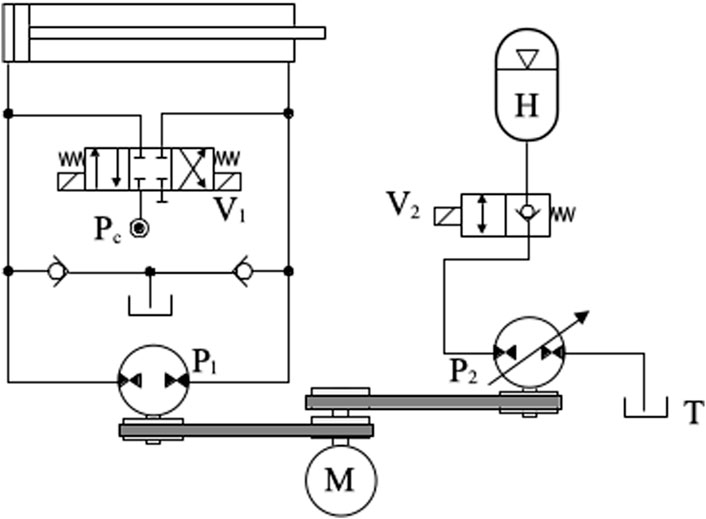
FIGURE 11. Energy storage circuit connected to a single-rod electrohydrostatic actuator.
With reference to Figure 11, valve V1, connected to a low-pressure source, Pc, is used to compensate for the uneven flows coming into and out of the differential cylinder [see Costa and Sepehri (2019) for details on the way in which valve V1 operates]. Since the pump and cylinder are directly connected, it is possible to transfer energy from the load to the main pump, P1. When this happens, we say that the circuit operates in the motoring mode, and P1 acts as a hydraulic motor. A belt and pulley transmission is used to connect P1 to the secondary pump P2, which loads the accumulator H when it pumps oil from the tank T. The variable displacement of the pump/motor, P2, can be shifted between a positive and negative value so that it guarantees that the flow between the tank and the accumulator is correctly directed. The energy stored in H can be later reused to assist the main pump, P1, by activating valve V2, thus reducing the overall energy consumption.
5 Accumulators in digital hydraulics
One interesting manner of providing a variable flow into the actuator without the use of throttling valves is through the use of a fast-switching electrovalve, V, as shown in Figure 12A. The idea is to modulate the electrical pulse width,
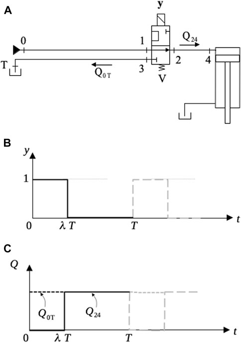
FIGURE 12. Pulse modulation flow control. (A) Hydraulic circuit, (B) Valve control signal, (C) Circuit flows.
Now consider the design shown in Figure 13 where an accumulator, H, is added to the circuit. In the figure, we have represented line 0-1 as in Brown et al. (1988) to emphasize the fact that it is a real conduit with an inner diameter,
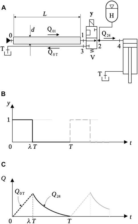
FIGURE 13. Ideal switched inertance circuit. (A) Hydraulic circuit, (B) Valve control signal, (C) Circuit flows.
Disregarding viscous losses in the circuit shown in Figure 12, the Second Law of Newton can be applied between points 0 and 1. Considering the hydraulic fluid with density
where
Equation 9 can be simplified and written as a function of the flow,
where
Integrating Eq. 10 for
In Figure 12C, we see the behavior of
Switched inertance circuits are challenging in many ways. The switching frequency, for instance, is an issue in conventional spool valves. Rotary valves have been suggested as a substitute; however, dynamic problems such as the appearance of cavitation voids in the fluid have been observed (Brown et al., 1988). Nevertheless, this is a promising field in which hydraulic accumulators play an important part.
6 Conclusion
In this review article, we presented some major fields where hydraulic accumulators can be used to increase energy efficiency and performance. The challenges concerning pressure and flow output have also been addressed, where we see that attempts have been made to produce a constant-pressure response. Still, no solution has become commercial, but as in many other aspects of technology, this may be a simple matter of time. It must also be said here that hydraulic accumulators have other aspects that not explored in this article, such as energy loss during charge and discharge due to non-isothermal behavior. These are themselves complex and would not be fairly covered in a single article, so a choice had to be made even in this article to pick up some significant aspects out of a fairly large choice of approaches. We thus know that it is not possible, by any means, to cover all aspects concerning hydraulic accumulators, especially if we note that new circuits and new designs are constantly being developed. The idea, however, has been to introduce the state-of-the-art and expose the challenges and achievements obtained so far in some significant fields of application.
Author contributions
GC contributed to conception, design, and writing of the manuscript. NS contributed by reviewing and improving the content of the submitted version. All authors contributed to the article and approved the submitted version.
Conflict of interest
The authors declare that the research was conducted in the absence of any commercial or financial relationships that could be construed as a potential conflict of interest.
Publisher’s note
All claims expressed in this article are solely those of the authors and do not necessarily represent those of their affiliated organizations, or those of the publisher, the editors and the reviewers. Any product that may be evaluated in this article, or claim that may be made by its manufacturer, is not guaranteed or endorsed by the publisher.
References
Beachley, N. H., Anscomb, C., and Burrows, C. R. (1983). Minimization of energy storage requirements for internal combustion engine hybrid vehicles. J. Dyn. Sys., Meas. Control 105 (2), 113–119. doi:10.1115/1.3149641
Bertolin, M., and Vacca, A. (2021). An energy efficient power-split hybrid transmission system to drive hydraulic implements in construction machines. ASME. J. Dyn. Sys., Meas. Control. 143 (10), 101005. doi:10.1115/1.4051035
Brown, F. T., Tentarelli, S. C., and Ramachandran, S. (1988). A hydraulic rotary switched-inertance servo-transformer. ASME. J. Dyn. Sys., Meas. Control. 110 (2), 144–150. doi:10.1115/1.3152664
Çalışkan, H., Balkan, T., and Platin, B. E. (2015). A complete analysis and a novel solution for instability in pump controlled asymmetric actuators. ASME. J. Dyn. Sys., Meas. Control. 137 (9), 091008. doi:10.1115/1.4030544
Chapp, R. (2004). Combined optimisation of design and power management of the hydraulic hybrid propulsion system for the 6 × 6 medium truck. Int. J. Veh. Des. Heavy Veh. Des. 3 (4), 372–402. doi:10.1504/IJHVS.2004.005458
Chen, Y., Zhang, T., Zhang, H., Zhang, Z., Jia, Q., Chen, H., et al. (2022). Study on the effect of hydraulic energy storage on the performance of electro-mechanical-hydraulic power-coupled electric vehicles. Electronics 11, 3344. doi:10.3390/electronics11203344
Costa, G. K., and Sepehri, N. (2019). Four-quadrant analysis and system design for single-rod hydrostatic actuators. ASME. J. Dyn. Sys., Meas. Control. 141 (2), 021011. doi:10.1115/1.4041382
Costa, G. K., and Sepehri, N. (2015). Hydrostatic transmissions and actuators—operation, modelling and applications. Chichester - UK: Wiley.
De Negri, V. J., Wang, P., Plummer, A., and Johnston, D. N. (2014). Behavioural prediction of hydraulic step-up switching converters. Int. J. Fluid Power 15 (1), 1–9. doi:10.1080/14399776.2014.882057
Deppen, T. O., Alleyne, A. G., Meyer, J. J., and Stelson, K. A. (2015). Comparative study of energy management strategies for hydraulic hybrids. ASME. J. Dyn. Sys., Meas. Control. 137 (4), 041002. doi:10.1115/1.4028525
Deppen, T. O., Alleyne, A. G., Stelson, K. A., and Meyer, J. J. (2012). Optimal energy use in a light weight hydraulic hybrid passenger vehicle. ASME. J. Dyn. Sys., Meas. Control. 134 (4), 041009. doi:10.1115/1.4006082
Dutta, R., Wang, F., Bohlmann, B. F., and Stelson, K. A. (2014). Analysis of short-term energy storage for midsize hydrostatic wind turbine. ASME. J. Dyn. Sys., Meas. Control. 136 (1), 011007. doi:10.1115/1.4025249
Fan, Y., and Mu, A. (2020). Adaptive fuzzy Proportion Integration Differentiation control in hydraulic offshore wind turbine for optimal power extraction based on the estimated wind speed. Energy Sci. Eng. 8, 1604–1619. doi:10.1002/ese3.618
Fan, Y., Mu, A., and Ma, T. (2016c). Design and control of a point absorber wave energy converter with an open loop hydraulic transmission. Energy Convers. Manag. 121, 13–21. doi:10.1016/j.enconman.2016.04.107
Fan, Y., Mu, A., and Ma, T. (2016a). Modeling and control of a hybrid wind-tidal turbine with hydraulic accumulator. Energy 112, 188–199. ISSN 0360-5442. doi:10.1016/j.energy.2016.06.072
Fan, Y., Mu, A., and Ma, T. (2016b). Study on the application of energy storage system in offshore wind turbine with hydraulic transmission. Energy Convers. Manag. 110, 338–346. doi:10.1016/j.enconman.2015.12.033
Heybroek, K., Vael, G., and Palmberg, J. (2012). “Towards resistance-free hydraulics in construction machinery,” in Proceedings of the 8th International Fluid Power Conference, Dresden, Germany, March 26-28, 2012, 123–138.
Hippalgaonkar, R., and Ivantysynova, M. (2016a). Optimal power management of hydraulic hybrid mobile machines—Part I: Theoretical studies, modeling and simulation. ASME. J. Dyn. Sys., Meas. Control. 138 (5), 051002. doi:10.1115/1.4032742
Hippalgaonkar, R., and Ivantysynova, M. (2016b). Optimal power management of hydraulic hybrid mobile machines—Part II: Machine implementation and measurements. ASME. J. Dyn. Sys., Meas. Control. 138 (5), 051003. doi:10.1115/1.4032743
Ho, T. H., and Ahn, K. K. (2010). Modeling and simulation of hydrostatic transmission system with energy regeneration using hydraulic accumulator. J. Mech. Sci. Technol. 24, 1163–1175. doi:10.1007/s12206-010-0313-8
Irizar, V., and Andreasen, C. S. (2017). Hydraulic pitch control system for wind turbines: Advanced modeling and verification of an hydraulic accumulator. Simul. Model. Pract. Theory 79, 1–22. ISSN 1569-190X. doi:10.1016/j.simpat.2017.09.002
Kogler, H., and Scheidl, R. (2016). Energy efficient linear drive Axis using a hydraulic switching converter. ASME. J. Dyn. Sys., Meas. Control. 138 (9), 091010. doi:10.1115/1.4033412
Leon-Quiroga, J., Newell, B., Krishnamurthy, M., Gonzalez-Mancera, A., and Garcia-Bravo, J. (2020). Energy efficiency comparison of hydraulic accumulators and ultracapacitors. Energies 13, 1632. doi:10.3390/en13071632
Lin, T., and Wang, Q. (2012). Hydraulic accumulator-motor-generator energy regeneration system for a hybrid hydraulic excavator. Chin. J. Mech. Eng. 25, 1121–1129. doi:10.3901/cjme.2012.06.1121
Liu, Y., Xu, Z., Hua, L., and Zhao, X. (2020). Analysis of energy characteristic and working performance of novel controllable hydraulic accumulator with simulation and experimental methods. Energy Convers. Manag. 221, 113196. ISSN 0196-8904. doi:10.1016/j.enconman.2020.113196
Pfeffer, A., Glück, T., Kemmetmüller, W., and Kugi, A. (2016). Mathematical modelling of a hydraulic accumulator for hydraulic hybrid drives. Math. Comput. Model. Dyn. Syst. 22 (5), 397–411. doi:10.1080/13873954.2016.1174716
Porumamilla, H., Kelkar, A. G., and Vogel, J. M. (2008). Modeling and verification of an innovative active pneumatic vibration isolation system. ASME. J. Dyn. Sys., Meas. Control. 130 (3), 031001. doi:10.1115/1.2807049
Pourmovahed, A., Beachley, N. H., and Fronczak, F. J. (1992). Modeling of a hydraulic energy regeneration system: Part I—analytical treatment. ASME. J. Dyn. Sys., Meas. Control. 114 (1), 155–159. doi:10.1115/1.2896497
Ren, H., Lin, T., Zhou, S., Huang, W., and Miao, C. (2018). Novel automatic idle speed control system with hydraulic accumulator and control strategy for construction machinery. Appl. Sci. 8, 496. doi:10.3390/app8040496
Shen, W., Jiang, J., Su, X. 2, and Karimi, H. R. (2013). Energy-saving analysis of hydraulic hybrid excavator based on common pressure Rail. Sci. World J. 2013, 1–12. doi:10.1155/2013/560694
Sprengel, M., and Ivantysynova, M. (2013). “Investigation and energetic analysis of a novel hydraulic hybrid architecture for on-road vehicles,” in The 13th Scandinavian International Conference on Fluid Power, SICFP2013, Linkoping, Sweden, June 3-5; 2013.
U.S. Environmental Protection Agency (2020). How series hydraulic hybrid vehicles work. Web Page, Available at: https://archive.epa.gov/otaq/technology/web/html/how-it-works.html (Accessed January 10, 2023).
Van de Ven, J. D. (2013). Constant pressure hydraulic energy storage through a variable area piston hydraulic accumulator. Appl. Energy 105, 262–270. ISSN 0306-2619. doi:10.1016/j.apenergy.2012.12.059
Wendel, G. R. (2002). “Hydraulic system configurations for improved efficiency,” in Proceedings of the 49th National Conference on Fluid Power – NCFP, USA, 567–573.
Yu, Y. X., and Ahn, K. K. (2020). Energy regeneration and reuse of excavator swing system with hydraulic accumulator. Int. J. Precis. Eng. Manuf.-Green Tech. 7, 859–873. doi:10.1007/s40684-019-00157-7
Yudell, A. C., and Van de Ven, J. D. (2017). Soft switching in switched inertance hydraulic circuits. ASME. J. Dyn. Sys., Meas. Control. 139 (12), 121007. doi:10.1115/1.4036887
Keywords: hydraulic accumulators, hydraulic circuits, energy harvesting, fluid power, power hydraulics
Citation: Costa GK and Sepehri N (2023) Hydraulic accumulators in energy efficient circuits. Front. Mech. Eng 9:1163293. doi: 10.3389/fmech.2023.1163293
Received: 10 February 2023; Accepted: 03 July 2023;
Published: 19 July 2023.
Edited by:
Sohel Anwar, Indiana University-Purdue University Indianapolis, United StatesReviewed by:
Sourav Pramanik, Purdue University, United StatesAnle Mu, Xi’an University of Technology, China
Copyright © 2023 Costa and Sepehri. This is an open-access article distributed under the terms of the Creative Commons Attribution License (CC BY). The use, distribution or reproduction in other forums is permitted, provided the original author(s) and the copyright owner(s) are credited and that the original publication in this journal is cited, in accordance with accepted academic practice. No use, distribution or reproduction is permitted which does not comply with these terms.
*Correspondence: Gustavo Koury Costa, Z3VzdGF2b2tvdXJ5QHJlY2lmZS5pZnBlLmVkdS5icg==