 F. Djamaluddin
- Department of Mechanical Engineering, Faculty of Engineering, Hasanuddin University, Gowa, Indonesia
Mainly composed of elastic materials, ship fenders are utilised on all kinds of vessels for the protection of berthing structures and the prevention of damage due to heavy crash loads. This study aims to enhance deformation mode and crash performance of foam-filled fenders under quasi-static and dynamic loadings. Six models of ship fender’s structure are chosen for simulation test. The fenders are examined for crashworthiness parameters such as crushing force efficiency (CFE) and specific energy absorption (SEA). Finite element analysis is conducted for estimating crash responses then compared to an appropriate reference and experiment result. Four design variables are considered for instance height, foam density, thickness, and material for optimization. Non-dominated Sorting Genetic Algorithm II as multi-objective optimization approach are used to obtain the maximum of Specific Energy Absorption (SEA) and the minimum of Crushing Force Efficiency (CFE). Based on the results of the optimization, the best performance is observed in model 5, however it can be replaced the traditional fender design.
1 Introduction
The main function of a marine fender is to absorb a berthing vessel’s impact energy through the conversion of kinetic energy into strain energy (Mostofi and Bargi, 2012). The method of energy dissipation used is intended to elicit dependence on the impact energy’s size and frequency. Ideally, a fender system consumes high input energy produced by berthing or moored ships at an acceptable building and maintenance cost. Using elastomeric rubber, foams, or springs as the principal element that absorbs energy according to an ideal marine system’s criterion for cost-effectiveness is one of the basic reasons for marine fender system’ extensive utilisation of elastic impact energy absorbers. There is a widespread use of elastic fender systems in commercial facilities that has various ship types, hull layouts, and sizes (Spencer, 2004).
Because of the elasticity of the berthing structure and the fender system, elastic energy absorbers are suitable to be used in low-energy collisions with no major consequent lasting damage (Voyiadjis, 2008). On the other hand, elastic energy absorbers observed with highly non-linear material reactions have the tendency to become unsuitable in case the system bears irreversible damage due to a high-energy collision. In addition, the elastic absorbers’ energy-absorbing properties and response forces are in direct proportion to the material’s stiffness, which, in turn, strongly depends on impact velocity and temperature. However, dispersing and regulating impact energy at an acceptable level of deceleration/force greatly enhances the maritime fenders’ structural crashworthiness as well as the safety of people. With the use of computational and experimental methodologies, studies have been conducted on the tactics used in describing the impact energy absorbers’ non-linear behaviour done in a controlled and progressive manner by means of plastic deformation that has excellent reproducibility.
The technique and amplitude of load application, deformation patterns, transmission rates, and material qualities are all essential elements for the conversion of kinetic energy into plastic deformation (Alghamdi, 2001). This research also investigated and presented various shapes and materials of impact energy absorbers that are deformable. In these experiments, the most common form is a metallic tube absorber that has a plastic collapse model (Zhang et al., 2009; Salehghaffari et al., 2010). This type of plastic energy absorber has been characterised as the element that has the most efficient energy absorption properties with uneven crushing loads, because of its multiple buckling modes. Metallic tubes initially require a strong force that can destroy berthing structures and injure people in colliding boats (Alghamdi, 2001; Zhang et al., 2009; Hassan et al., 2015). Consequently, to assess the need to make plastic impact energy absorbers more structurally optimised, studies were carried out to explore new configurations, geometries, and material combinations (Hassan et al., 2015). The latest modifications to the rules that classify sea-going steel ships that have fenders and comparable structures in collision zones require improving dredger side plates. Usually found on engineering ships such as dredgers and barges, fender structures provide a system for the absorption or dispersal of a substantial portion of the impact energy of the berthing ship with no permanent deformation on the ship’s side structures. Ship fenders include rubber, lumber, steel, and pneumatic fenders, as per (Zhao et al., 2000). Because of their comparatively low-cost prices, high strength-to-weight ratio, and superior capabilities to absorb energy, steel fenders are still normally used by small and medium-sized boats (Yamazaki and Han, 1998).
Figure 1 shows a small ship that has fenders on both sides. Since fender structures often encounter considerable kinematic deformation induced by crushing, protecting the hull plates has seen two crucial problems in thin-walled structure design: specifically, how to optimise their capacities to absorb energy and minimise the crushing pressures at the time of impact (Taghipoor and Eyvazian, 2022). Earlier testing and computational analysis (Liu, 2008; Taghipoor et al., 2020; Taghipoor et al., 2021) noted that it is possible that the structures’ crashworthiness could be enhanced using modern materials or the optimisation of the shape configurations (Yamazaki and Han, 2000). Yamazaki and Han (Kim, 2002) explored improving the cylindrical shells’ design to enhance their crushing energy (Kim, 2002). Kim (US Army Corps of Engineers, 2005) also suggested new cross-sections with several square cells at the corner. In different studies, Hou et al. (Taghipoor and Eyvazian, 2022) and Liu (Liu, 2008) reviewed the best multi-corner construction designs that have good crash performance. The preliminary research demonstrates that the traditional structures’ crashworthiness is improved when the sectional profiles or geometric proportions undergo redesign and optimisation. Still, little attention has been given to the optimisation of crash-worthy aluminium foam-filled fenders. This is because the durability and crash performance of many fenders are inadequate. Medium-sized ships increasingly use fenders for economic reasons; thus, to manufacture fenders with the highest possible crashworthiness post-collision, optimisation of their geometric characteristics is necessary. For that reason, this study suggests an aluminium foam-filled fender structure with an optimal design that maximises the efficient absorption of energy while it improves structural safety.
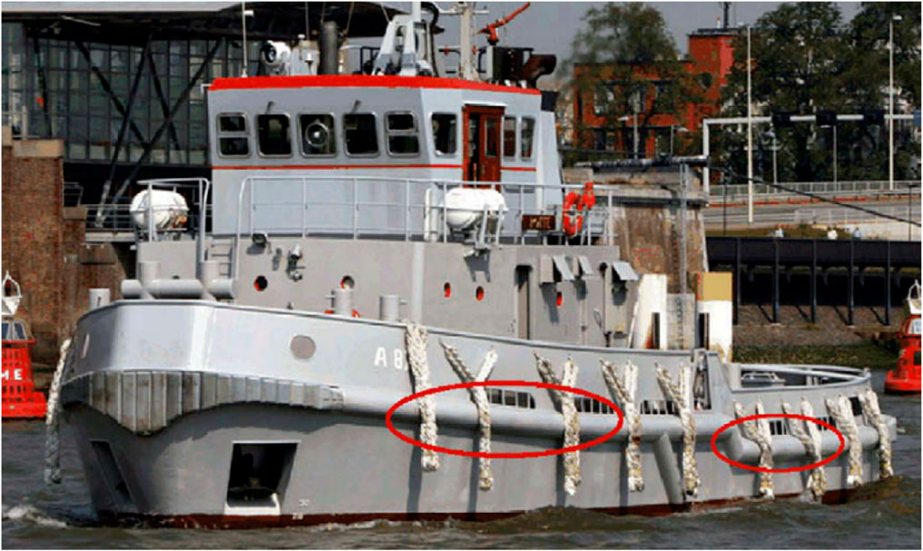
FIGURE 1. Fender of ship (Jiang et al., 2010).
Aluminium foam has been noticed as an innovative cellular material for absorbing energy and reducing load because of its strong load resistance and low density (Banhart, 2001; Gama et al., 2001; Banhart, 2011; Yin et al., 2015; Sun et al., 2016; Sun et al., 2019). Different hybrid applications using composite or metallic hollow structures have highlighted aluminium foam as an efficient technique for the further improvement of the crashworthiness and lightweight properties of fender structures (Fang et al., 2014a; Duarte et al., 2014; Sun et al., 2018). This study emphasises the foam-filled columns’ crashworthiness because of developing metallic foam materials for the past two decades. Employing experimental and simulation methods, Mirfendereski et al. (2008) tested foam-filled straight, double-tapered, triple-tapered, and frusta geometries to explore crashworthiness properties for dynamic and static impact loads. Based on the results, initial peak load drops as the number of oblique sides increases (Mirfendereski et al., 2008). Foam-filled conical columns absorb substantially more energy and therefore have greater mean crush loads than empty columns, as stated by Ahmad and Thambiratnam (2009). Goel (2015) assessed the energy absorption capacities of foam-filled and empty columns across diverse cross-sections under various impact loading conditions and discovered that foam-filled mono-tubular columns absorb less energy than foam-filled tri-tubular and bi-tubular columns. Altin et al. (2017) carried out axial crushing experiments using empty and partially foam-filled thin-walled circular columns and found that square columns performed best (Altin et al., 2017). Metallic foam can assist in improving their capacity for energy absorption. Nevertheless, the impacts of foam densities and cross-sectional shapes have been extensively examined in efforts to strengthen crashworthiness performance. As stated by Langseth and Hopperstad (Langseth et al., 2003), increased column foam density and wall thickness enhanced SEA values under axial loading conditions. Hanssen et al. examined the crushing behaviour of square and circular columns filled with aluminium foam under various dynamic and static loads (Hanssen et al., 2000a; Hanssen et al., 2000b; Hanssen et al., 2001). Sun et al. (2018) also carried out research on thin-walled foam-filled circular columns using theoretical formulations, to predict maximum and forces as well as effective crushing distances.
Crash simulations are computationally intensive, and the associated cost is a major concern hindering crashworthiness assessment and evaluation. Addressing computational problems typically requires the use of meta-models or RBFs like simulation framework results. Moreover, optimisation research uses meta-models to assess structural crashworthiness (Tanlak, 2016; Karagöz and Yıldız, 2017; Renreng and F Djamaluddin, 2019; Djamaluddin and Mat, 2021; Djamaluddin, 2022b; Djamaluddin et al., 2051); the emphasis is on evaluating how thin-walled systems absorb energy. Extensive research has been performed to enhance the crashworthiness of foam-packed columns by altering wall dimensions and foam density. For instance, Hou et al. (2009) employed multi-objective optimisation to enhance foam-packed crash absorbers having a square mono-tubular structure. Foam filling enhances SEA, leading to higher peak crush force, enhancing crashworthiness characteristics (Hou et al., 2009). Bi et al. (2010) performed design and improvement studies concerning mono- and tri-tubular columns packed with foam. A comparison of the energy absorption characteristics of unfilled, foam-filled, and honeycomb-packed columns using dynamic crushing loading prompted Zarei and Kröger (Zarei and Kröger, 2007; Zarei and Kröger, 2008) to use the multi-criteria design improvement method to enhance mono-tubular and tri-tubular columns to enhance SEA capacity. The authors highlighted the benefits of using foam-loaded columns and their energy absorption ability (Zarei and Kröger, 2007). Zheng et al. (2014) evaluated eight distinct mono- and bi-tubular structure; three impact speeds were used to test them. The outcomes indicated that the optimal structure is dependent on the impact. Single- and multiple-optimisation approaches were used to test the crashworthiness of proposed designs using several optimisation approaches like the Multi-objective Particle Swarm Optimization (MOPSO) algorithm (Zhang et al., 2012; Tran et al., 2014a; Tran et al., 2014b; Sun et al., 2014), Non-Dominated Sorting Genetic Algorithm (NSGA-II) (Acar et al., 2011; Djamaluddin et al., 2015; Gao et al., 2016a), Genetic Algorithm (GA), and others (Jiang et al., 2010; Djamaluddin et al., 2018; Djamaluddin et al., 2019; Renreng et al., 2020).
The primary aim of this study is to enhance the material characteristics and geometry of foam-loaded ship fenders to maximise crashworthiness for such aluminium fenders. Crasworthiness performances of foam filled fender are evaluated using ABAQUS software and also the optimum results are determined using NSGA II and RBF.
2 Materials and methods
2.1 Crashworthiness indicator of fender under axial loadings
PCF, SEA, and Energy Absorption (EA) are metrics employed to assess structures’ crashworthiness and energy absorption. The EA is calculated as follows (Salehghaffari et al., 2010):
Where
The SEA indicates the energy the structure absorbs (EAtotal) for one unit mass (Mtotal); it is expressed as:
Crush force efficiency (Fmax) is expressed as the ratio of average (Favg) to peak crush force (Kim, 2002):
2.2 Finite element models of the fender
Figure 2 depicts the architecture of a ship fender having 100 mm and 600 mm height and length (constant value) respectively, impacted to transfersal load (Jiang et al., 2010). As Figure 3 indicates, fenders have six types such as foam-filled double and single foam fender.
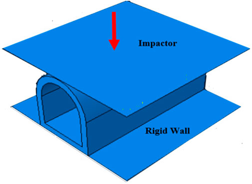
FIGURE 2. The fender structure.
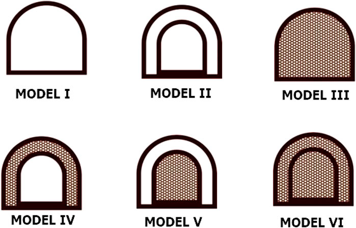
FIGURE 3. Cross-section of fender (6 models).
The impactor speeds are 0.2 m/s for quasi-static loads and 1 m/s (approximately 2 knots) for dynamic loads. A 1200 T weight is added to simulate speed collisions that fenders typically encounter. The impactor transitions to squash the structures, and the solid wall permits better deformation characteristics. Neck berthing is a frequently encountered situation. The dynamic force on the assessed fender length is assumed uniform based on this situation. On the other hand, the impact might be unpredictable on the structure of the fender and its rough and non-uniform surface (Guo and Yu, 2011a).
Figure 3 and Figure 4 presents the cross-section and the finite element model comprising six types foam filled single and double fender structures The Finite Element (FE) ABAQUS software was used to build the fender comprising aluminium foam filling and determine the effect of a free-falling mass impacting thin walls. This research integrated the fender with a hull and it offered a stationary boundary.
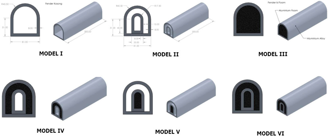
FIGURE 4. The Finite Element (FE) for 6 models of fender structure.
The walls of the fenders were modelled using four node shell continuum elements with five integration points along the element’s thickness direction. Moreover, the foam was modelled using eight node continuum elements with a reduced integration technique combined with the hourglass control. To avoid both artificial zero energy deformation modes and volumetric locking, enhancement-based hourglass control and reduced integration were applied. Based on a mesh convergence study of shells and foam elements, a 2 mm element size was chosen. A mesh convergence was addressed to ensure a sufficient mesh density and to accurately capture the deformation process. The contact interaction between all components was the general contact algorithm used to avoid interpenetration of fender walls, which is less intense in terms of computational time. Meanwhile, the contacts between the foam and the fender walls were modelled as a finite sliding penalty based contact algorithm, with contact pairs and a hard contact. The friction coefficient value for all contact surfaces was set at 0.3.
2.3 Material properties
2.3.1 Fender material
The A6063 T6 aluminium alloy was used to produce the fender (Fang et al., 2014a; Yin et al., 2015). The material has density of 2,700 kg/m3, initial yield stress of 184.4 MPa, ultimate stress of 215.5 MPa and Young modulus of 60.2 GPa, The tubes’ constitutive phenomena were evaluated through an elastic-plastic material structure and Von Mises’ isotropic plasticity technique. Moreover, we disregarded the manufacturing impact created by aluminium foam orientation. The constitutive material approach comprised the use of piecewise lines to specify plastic stiffening. The true plastic strain and stress were determined using experiments to ascertain the piecewise lines. Different A6063 T6 aluminium alloy thicknesses were used to compute the uniaxial tension outcomes (Guo and Yu, 2011b). The aluminium alloy had strain insensitivity; hence, strain speed and its impact were disregarded. It was done because aluminium alloy fracturing characteristics were not accounted for in the evaluation.
2.3.2 Aluminium foam-filled material
This research used a closed-cell aluminium foam as a filler material that was tested to understand its average mechanical characteristics. Experimental assessment of the foam-loaded material indicated its characteristics. At the same time, studies (Langseth and Hopperstad, 1996) specify uniaxial quasi-static compression outcomes for several foam density values.
The constitutive behaviour was based on an isotropic uniform material of the foam model developed by Deshpande and Fleck (2000) using ABAQUS/Explicit software. The effect of the manufacturing process for anisotropic behaviour of aluminium foam was not considered in this work. Table 1 shows the details of the material’s parameters used in the FE simulation.
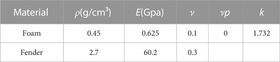
TABLE 1. The materials’ parameters (Deshpande and Fleck, 2000).
2.4 Design of experiment and meta-model technique
The meta-model comprises a mathematical method to use simulations to create outputs using the gathered input data. Such a model helps assess physical properties through several datasets employed to implement distinct meta-models. The experimental design comprises setting points in an area, e.g., data collection inputs (Fang et al., 2005). Test data based on physical evaluations or computer simulations based on the finite element technique were employed to build meta-models. The design space was used to identify useful data by specifying parameter ranges that were split into several points. Every point indicates several variables having different levels. The meta-model creation process uses DOE to reduce input data. It is a statistical approach to gather data using several simulations based on different variables to understand specific characteristics (Yin et al., 2014).
Radial Basis Function (RBF) is employed for geographic data and fixes non-uniform topology boundaries. RBF was used for several situations, including objective function approximation. Fang et al. (Gao et al., 2016b) used the RBF meta-model to optimise several vehicle body requirements concerning frontal impact. It was validated using finite element simulations to estimate the general vehicle structure. Considering an equal number of reaction observations, the outcomes indicated that RBF was better than RSM because of optimal result more accuracy and stability. Additionally, impact absorption ability was determined based on the fewest applicable analytical variables to construct the RBF framework. Evolutionary algorithms are integrated with surface reactions to create single- and multiple-objective constraints. Implementing single restrictions and multiple-objective optimisation required genetic algorithms to be integrated with surface reactions. Outcomes concerning circular tubes indicated moderate eccentricity outcomes leading to high construction efficiency. Structures had uniform forward crushing reactions and desirable impact absorption. The outcomes indicated up to 7% and 20% mass reduction and vertical impact results, respectively (Fang et al., 2014b).
2.5 Multi-objective optimization
The multi-objective optimisation design (MOD) was performed by using sectional design parameters such as wall thickness t, height h, foam density f, yield stress y, and a 600 mm constant length tube. Furthermore, several early studies (Lanzi et al., 2004) investigated 2 crashworthiness indicators that are tweaked simultaneously to identify the lowest CFE and maximum SEA when subjected to transverse impact loadings. The GA (Genetic Algorithm) is a standard optimisation technique since it bypasses the trapping capacity when searching in local optima for an optimum (Salehghaffari et al., 2011). For grading solutions, assigning ranking fitness, and determining number problems, the NSGA (Non-dominated Sorting GA) technique, such as the NSGA versions I and II, is a more efficient and favourable approach. Figure 5 illustrates the flowchart for optimising the double fender’s crashworthiness under impact loadings. The DOE method was used in the preliminary step to specify the design space and produce sampling sites for different angle loadings. The design solutions for the preliminary D-optimal models of the design objectives were attained using FEA in the 2nd phase. Lastly, Pareto solutions of systems under stress are obtained in the 3rd phase. In the 3rd phase, the NSGA II method was used to obtain Pareto solutions of systems under different loading situations.
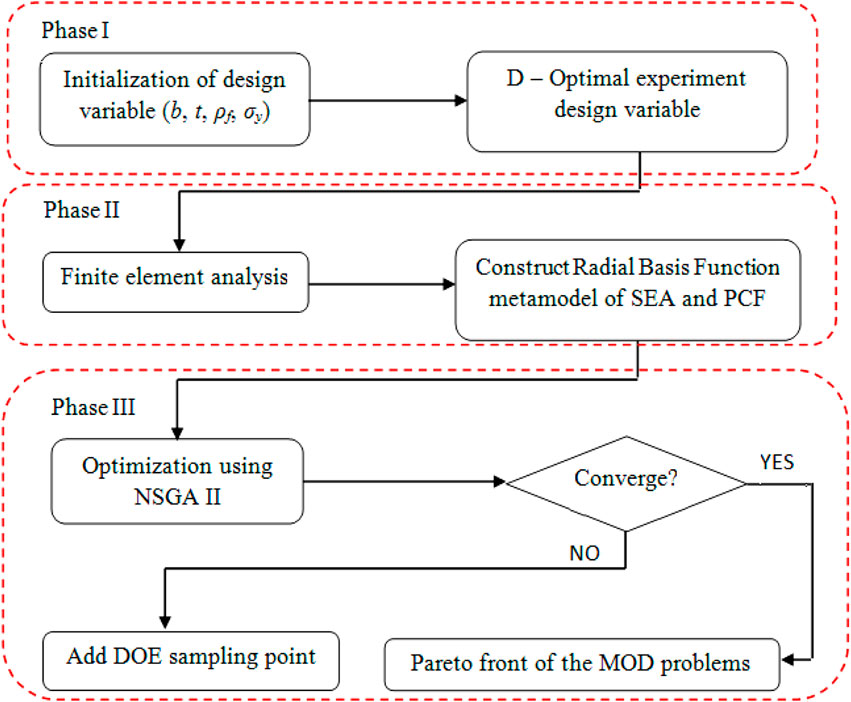
FIGURE 5. Flowchart of crashworthiness multi-objective optimization for tubes [81].
3 Results and discussion
3.1 Model validation
The specimens were carried out from the casting method. The fenders molds were made using iron plate. After that, the aluminum alloy 6,063 material melts into the fender molds (shown in Figure 6).
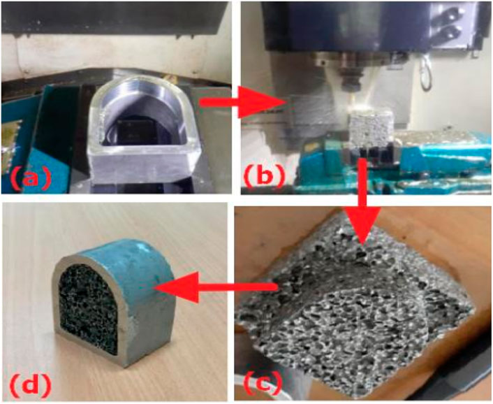
FIGURE 6. Process of fender specimen manufacturing: (A) fender specimen from the casting process (B) CNC process of foam (C) Formed foam (D) Foam filled fender.
Finite element models making use of the ABAQUS were compared to outcomes of the investigation to determine if they were satisfactorily accurate for design optimisation. Moreover, simulation study was carried out using side frames with height 100 mm and a length of 50 mm to determine the value under the axial collision of fender (shown in Figure 7 and Table 2). The section view of deformations in Figure 7 compare between simulation and experiment results under axial load. It can be seen also in Table 2, the errors percentage between FEA and theoretical solutions are fairly small and it found that they have a sufficient agreement.
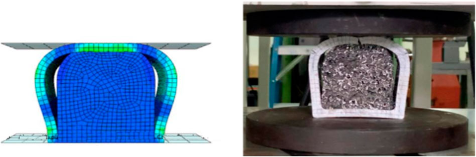
FIGURE 7. Simulation and experiment results.
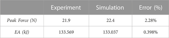
TABLE 2. Differences between experiment and FE ABAQUS.
FEA model also compared between ABAQUS and LS DYNA results (Jiang et al., 2010). The fender impacted with velocity of 1 m/s, the weight of the 1200 T and fender length of 600 mm under the tranverse impact (in Figure 8). From Table 3 also can be found that a good agreement between both results (Jiang et al., 2010).
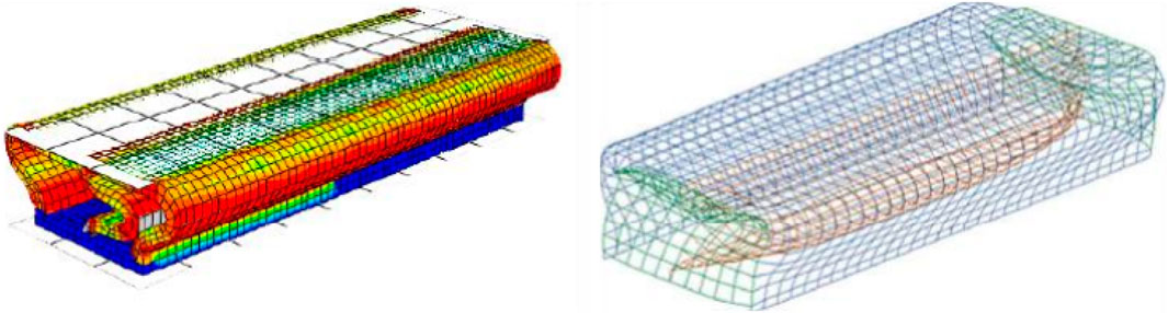
FIGURE 8. Simulation using ABAQUS and reference (Jiang et al., 2010).
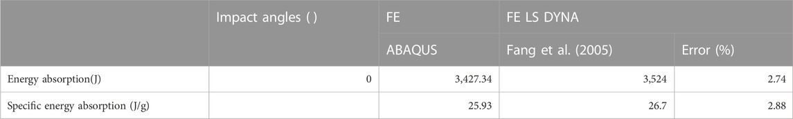
TABLE 3. Differences between FE LS DYNA and FE ABAQUS results (Jiang et al., 2010).
To find the sample points accurately, a radial basis functions meta-model was created. Moreover, within the design spheres of the 6 kinds of tubes made to undergo the axial stress, five extra random points (Hanssen et al., 2000a; Langseth et al., 2003) were generated. The responses of PCF and SEA at validation sites of the RBF and FE models were used to substantiate these models at a reduced cost. To determine the radial basis functions meta-model’s degree of approximation to the FEA results, the Relative Error (RE) (Renreng et al., 2020) is computed as follows:
where
In five random sample points, the initial sample points pertain to the RBF and the FEA. Figures 9–11 show that the RE for these approximations of RBF meta-model was below 4% in model IV, V and VI. Therefore, the RBF model for the goal functions (PCF and SEA) is considered to have given satisfactory accuracy for optimisation of design. In 5 random sample points, the initial sample points pertain to the RBF and the FEA. Figures 7–9 show that the RE for these approximations of RBF meta-model was below 4%. Therefore, the RBF model for the goal functions (PCF and SEA) is considered to have given satisfactory accuracy for optimisation of design.
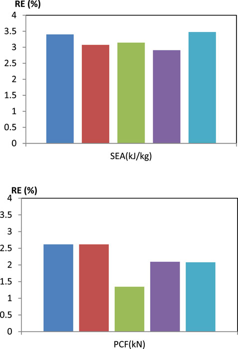
FIGURE 9. Relative errors of Model IV.
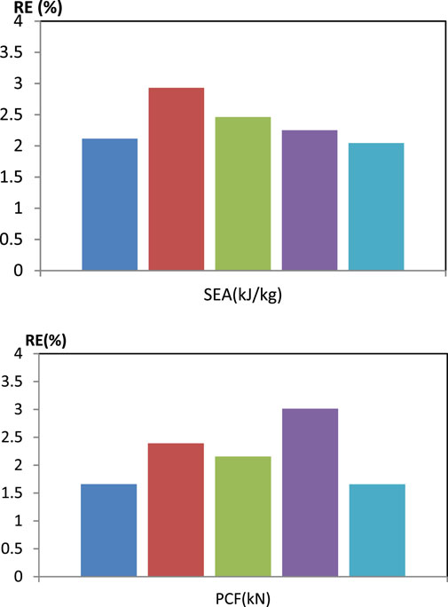
FIGURE 10. Relative errors of model V.
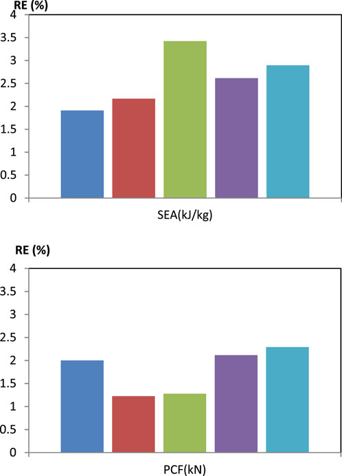
FIGURE 11. Relative errors of model VI.
3.2 Comparison of the fender structures under transverse impact loadings
The deformation configurations of the fenders under quasi static and dynamic loadings are shown in Figures 12, 13. Also, the force—displacement diagrams can be seen in Figures 14, 15. From these figures, they can be seen that foam-filled double fenders (model IV—VI) have more ability to absorb energy than single fender. This phenomenon is caused the frictional interaction between the walls of the inner and outer fenders and the foam. Figure 15 shows displacement–force graphs of different cross section foam filled fenders under static and dynamic loadings. By regarding this figure, we can see that the highest PCF of 436.5 N for model IV and 762 N for model V under quasi static and dynamic loadings, respectively.
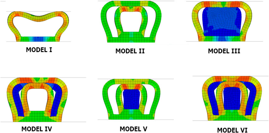
FIGURE 12. Deformation pattern of different structures under quasi static respon.
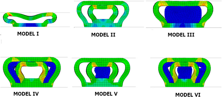
FIGURE 13. Deformation pattern of different structures under dynamic respon.
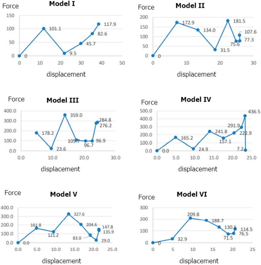
FIGURE 14. Force—displacement diagram of different structures under quasi static responses.
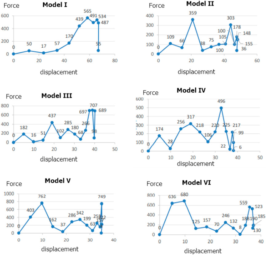
FIGURE 15. Force—displacement diagram of different structures under dynamic responses.
The geometry of the empty fender has weaker energy absorption compared to structures of other configurations that are exposed to transverse loadings, as displayed in Figure 16 and Figure 17. The combination structures showed higher energy absorption capacity and decreased peak crushing force because of the frictional contact between the inner/outer tubes and the foam-filler (Langseth et al., 2003; Salehghaffari et al., 2011). Consequently, these constructions have the capacity to improve the crashworthiness of shallow-walled tubes, especially those utilised in ship fenders.
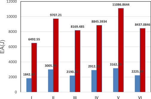
FIGURE 16. Energy absorption capability.
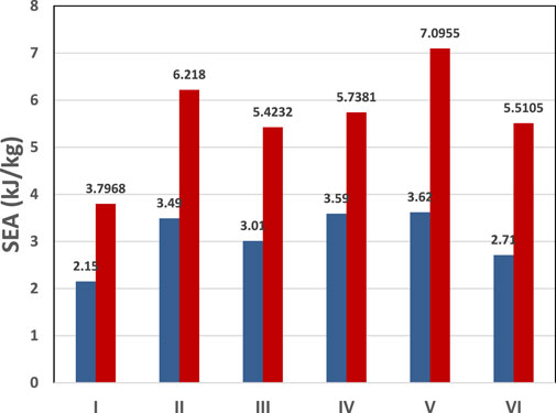
FIGURE 17. Specific energy absorption capability.
Based on the crashworthiness parameters, for quasi static loading, the highest energy absorption value is the model V with SEA value of 3.62 kg/kJ and the lowest one is model I with SEA value of 2.15 kg/kJ. However for dynamic loading, the highest energy absorption value is the model V with SEA value of 7.09 kg/kJ and the lowest one is model I with SEA value of 3.79 kg/kJ.
3.3 Crashworthiness optimisation design
To optimize the structure, four design variables and each varies within its domain were considered in this study. The design ranges of all the parameters are determined based on practical concerns. Considering the FE simulation runs affordable, this work selects D-Optimal design sample points (see Table 4).
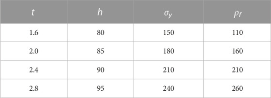
TABLE 4. Design variables levels.
Several parameters were used to produce the equations for the multi-objective optimisation of aluminium foam double tube. Multi-objectives were also employed when there was the issue of trade-offs among two or more opposing objectives. With respect to design parameters such as t, h, σy, ρf and objective functions, that is PCF and SEA for double circular tubes, new constraint functions and objectives were established.
The Pareto fronts are figured by using MOD problems, as indicated in Eq. 5. The NSGA-II technique was used to investigate the design domain using radial basis functions meta-models. Moreover, the DOE technique was used to create an initial group of 200 design points for all MOD conditions. Pareto fronts graphs of CFE vs. SEA for model V were built using NSGA-II by determining the convergence of optimisations repeating for 20 generations. In both CFE and SEA criterion design situations, they were clearly in disagreement with one another. As shown in Figure 18, there was increase in SEA, which led to an unsuitable rise in CFE.
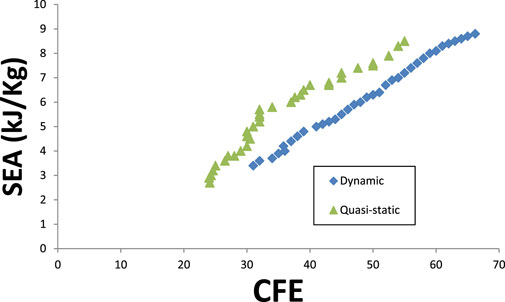
FIGURE 18. Pareto fronts for model V.
To define the faults between the radial basis functions models and the FEA, multi-objective optimisation was examined with respect to the design parameters of sectional fender of thickness t, height h, foam density f, and yield stress y. The NSGA-II optimisation and radial basis functions method were used to determine the Pareto fronts (shown in Figure 18) using five random sample points (Hanssen et al., 2000a). Under transversal loading conditions, all fenders were optimised. To determine the entry of foam-filler into the simulation of crashworthiness, suitable RBF models and MOD issues were used.
From Table 5, the optimal value of model V is in columns 4–7. Two objective functions such as SEA are in column 8 and PCF in column 9. It can be see that the structure designs in this table, it is found that the maximum SEA at 30.06 kJ/kg is achieved when the model V under dynamic impact. The wall thickness value is 2.49 mm which the material yield stress is 238.86 MPa.
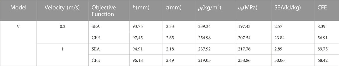
TABLE 5. The optimal value of model V.
4 Conclusion
In concluding the investigation, the design of crashworthiness for fender structures constructed of aluminium foam-filled circular tubes was examined in this research. It also evaluated crashworthiness metrics including SEA (Specific Energy Absorption) and CFE (Crushing Force Efficiency) when transverse forces were used. Finite Element Analysis (FEA) was utilised to construct multi-objective problems based on Radial Basis Functions (RBF) (FEA). As per the research, the lowest CFE and maximum SEA were 2.57 kN and 89.75 kJ/kg, respectively.
The following are the main observations: For the multi-objective optimisation of CFE and SEA for circular dual tubes, the NSGA-II (Non-dominated Sorting Genetic Algorithm-II) was used first. Then, it was used to optimise several structures, quasi-static and dynamic response. Lastly, with respect to transversal impact, model five samples were potential candidates for energy-absorbing crashworthiness ship constructions to guard against impacts.
Data availability statement
The original contributions presented in the study are included in the article/supplementary material, further inquiries can be directed to the corresponding author.
Author contributions
The author confirms being the sole contributor of this work and has approved it for publication.
Conflict of interest
The author declares that the research was conducted in the absence of any commercial or financial relationships that could be construed as a potential conflict of interest.
Publisher’s note
All claims expressed in this article are solely those of the authors and do not necessarily represent those of their affiliated organizations, or those of the publisher, the editors and the reviewers. Any product that may be evaluated in this article, or claim that may be made by its manufacturer, is not guaranteed or endorsed by the publisher.
References
Acar, E., Guler, M. A., Gerçeker, B., Cerit, M. E., and Bayram, B. (2011). Multi-objective crashworthiness optimization of tapered thin-walled tubes with axisymmetric indentations. Thin-Walled Struct. 49, 94–105. doi:10.1016/j.tws.2010.08.010
Ahmad, Z., and Thambiratnam, D. (2009). Crushing response of foam-filled conical tubes under quasi-static axial loading. Mater. Des. 30 (7), 2393–2403. doi:10.1016/j.matdes.2008.10.017
Alghamdi, A. A. A. (2001). Collapsible impact energy absorbers: An overview. Thin-Walled Struct. 2, 189–213. doi:10.1016/S0263-8231(00)00048-3
Altin, M., Güler, M. A., and Mert, S. K. (2017). The effect of percent foamfill ratio on the energy absorption capacity of axially compressed thin-walled multi-cell square and circular tubes. Int. J. Mech. Sci. 131, 368–379. doi:10.1016/j.ijmecsci.2017.07.003
Banhart, J. (2011). Aluminum foams: On the road to real applications. MRS Bull. 28, 290–295. doi:10.1557/mrs2003.83
Banhart, J. (2001). Manufacture, characterisation and application of cellular metals and metal foams. Prog. Mater Sci. 46, 559–632. doi:10.1016/s0079-6425(00)00002-5
Bi, J., Fang, H., Wang, Q., and Ren, X. (2010). Modeling and optimization of foam-filled thinwalled columns for crashworthiness designs. Finite Elem. Anal. Des. 46 (9), 698–709. doi:10.1016/j.finel.2010.03.008
Deshpande, V. S., and Fleck, N. A. (2000). Isotropic constitutive models for metallic foams. J. Mech. Phys. Solids 48, 1253–1283. doi:10.1016/s0022-5096(99)00082-4
Djamaluddin, F., and Mat, F. (2021). Optimization and crush characteristic of foam-filled fender subjected to transverse loads. Ocean. Eng. 242, 110085. doi:10.1016/j.oceaneng.2021.110085
Djamaluddin, F., Mat, F., Sarah, Z., Ahmad, M., and Renreng, I. (2051). “Analysis of energy absorption of aluminium foam fenders under axial loads,” in Journal of Physics: Conference Series, Perlis, Malaysia, 23rd August 2021.
Djamaluddin, F. (2022). Optimization of ship fender under axial load using Taguchi. WSEAS Trans. Appl. Theor. Mech. 17, 132–135. doi:10.37394/232011.2022.17.18
Djamaluddin, F., Abdullah, S., Ariffin, A. K., and Nopiah, Z. M. (2015). Multi objective optimization of foam-filled circular tubes for quasi-static and dynamic responses. Lat. Am. J. Solids Struct. 12, 1126–1143. doi:10.1590/1679-78251638
Djamaluddin, F., Abdullah, S., Ariffin, A. K., and Nopiah, Z. M. (2019). Optimisation and validation of full and half foam filled double circular tube under multiple load cases. J. Crashworthiness 24 (4), 389–398. doi:10.1080/13588265.2018.1454375
Djamaluddin, F., Abdullah, S., Arrifin, A. K., and Nopiah, Z. M. (2018). Crush analysis of the foamfilled bitubal circular tube under oblique impact. IOP Conf. Ser. Mater. Sci. Eng. 308, 012040. doi:10.1088/1757-899x/308/1/012040
Duarte, I., Vesenjak, M., and Krstulovi -Opara, L. (2014). Dynamic and quasi-static bending behaviour of thin-walled aluminium tubes filled with aluminium foam. Compos Struct. 109, 48–56. doi:10.1016/j.compstruct.2013.10.040
Fang, H., Rais-Rohani, M., Liu, Z., and Horstemeyer, M. F. (2005). A comparative study of metamodeling methods for multiobjective crashworthiness optimization. Comput. Struct. 85, 2121–2136. doi:10.1016/j.compstruc.2005.02.025
Fang, J., Gao, Y., Sun, G., Zhang, Y., and Li, Q. (2014). Parametric analysis and multiobjective optimization for functionally graded foam-filled thin-wall tube under lateral impact. Comput. Mater Sci. 90, 265–275. doi:10.1016/j.commatsci.2014.03.044
Fang, J., Gao, Y., Sun, G., Zhang, Y., and Li, Q. (2014). Crashworthiness design of foam-filled bitubal structures with uncertainty. Int. J. Non-linear Mech. 65, 120–132. doi:10.1016/j.ijnonlinmec.2014.08.005
Gama, B. A., Bogetti, T. A., Fink, B. K., Yu, C-J., Dennis Claar, T., Eifert, H. H., et al. (2001). Aluminum foam integral armor: A new dimension in armor design. Compos Struct. 52, 381–395. doi:10.1016/s0263-8223(01)00029-0
Gao, Q., Wang, L., Wang, Y., and Wang, C. (2016). Crushing analysis and multiobjective crashworthiness optimization of foam-filled ellipse tubes under oblique impact loading. Thin-Walled Struct. 100, 105–112. doi:10.1016/j.tws.2015.11.020
Gao, Q., Wang, L., Wang, Y., Wang, C., and Zhang, Z. (2016). Optimization of foam-filled double ellipse tubes under multiple loading cases. Adv. Eng. Softw. 99, 27–35. doi:10.1016/j.advengsoft.2016.05.001
Goel, M. D. (2015). Deformation, energy absorption and crushing behavior of single-double-and multi-wall foamfilled square and circular tubes. Thin-Walled Struct. 90, 1–11. doi:10.1016/j.tws.2015.01.004
Guo, L. W., and Yu, J. L. (2011). Bending behavior of aluminum foam-filled double cylindrical tubes. Acta Mech. 222, 233–244. doi:10.1007/s00707-011-0537-4
Guo, L. W., and Yu, J. L. (2011). Dynamic bending response of double cylindrical tubes filled with aluminum foam. Int. J. Impact Eng. 38 (2–3), 85–94. doi:10.1016/j.ijimpeng.2010.10.004
Hanssen, A. G., Langseth, M., and Hopperstad, O. S. (2000). Static and dynamic crushing of circular aluminium extrusions with aluminium foamfiller. Int. J. Impact Eng. 24 (5), 475–507. doi:10.1016/s0734-743x(99)00170-0
Hanssen, A. G., Langseth, M., and Hopperstad, O. S. (2000). Static and dynamic crushing of square aluminium extrusions with aluminium foamfiller. Int. J. Impact Eng. 24 (4), 347–383. doi:10.1016/s0734-743x(99)00169-4
Hanssen, A., Langseth, M., and Hopperstad, O. (2001). Optimum design for energy absorption of square aluminium columns with aluminium foamfiller. Int. J. Mech. Sci. 43 (1), 153–176. doi:10.1016/s0020-7403(99)00108-3
Hassan, M., Ghani, A., Taha, Z., and Hamdi, M. (2015). Mechanics of energy absorption by progressive plastic deformation of a square column with an ellipsoidal bulge base. Appl. Math. Inf. Sci. 1, 51–58. doi:10.12785/amis/091l06
Hou, S., Li, Q., Long, S., Yang, X., and Li, W. (2009). Crashworthiness design for foamfilled thinwall structures. Mater. Des. 30 (6), 2024–2032. doi:10.1016/j.matdes.2008.08.044
Jiang, Z., Gu, M., and March, M. (2010). Optimization of a fender structure for the crashworthiness design. Mater. Des. 31, 1085–1095. doi:10.1016/j.matdes.2009.09.047
Karagöz, S., and Yıldız, A. R. (2017). A comparison of recent metaheuristic algorithms for crashworthiness optimisation of vehicle thin-walled tubes considering sheet metal forming effects. Int. J. Veh. Des. 73 (1–3), 179–188. doi:10.1504/ijvd.2017.10003410
Kim, H. S. (2002). New extruded multi-cell aluminum profile for maximum crash energy absorption and weight efficiency. Thin-Walled Struct. 40 (4), 311–327. doi:10.1016/s0263-8231(01)00069-6
Langseth, M., and Hopperstad, O. S. (1996). Static and dynamic axial crushing of square thin-walled aluminium extrusions. Int. J. Impact Eng. 18, 949–968. doi:10.1016/s0734-743x(96)00025-5
Langseth, M., and Hanssen, A. G. (2003). “Crashworthiness of aluminium structures,” in Aluminium structural design. Editor F. M. Mazzolani (Vienna, Vienna: Springer), 313–394.
Lanzi, L., Castelletti, L. M. L., and Anghileri, M. (2004). Multi-objective optimisation of composite absorber shape under crashworthiness requirements. Compos. Struct. 65 (3-4), 433–441. doi:10.1016/j.compstruct.2003.12.005
Liu, Y. (2008). Crashworthiness design of multi-corner thin-walled columns. ThinWalled Struct. 46, 1329–1337. doi:10.1016/j.tws.2008.04.003
Mirfendereski, L., Salimi, M., and Ziaei-Rad, S. (2008). Parametric study and numerical analysis of empty and foam-filled thin-walled tubes under static and dynamic loadings. Int. J. Mech. Sci. 50 (6), 1042–1057. doi:10.1016/j.ijmecsci.2008.02.007
Mostofi, A., and Bargi, K. (2012). New concept in analysis offloating piers for ship berthing impact. Mar. Struct. 25, 58–70. doi:10.1016/j.marstruc.2011.12.001
Renreng, I., and F Djamaluddin, F. (2019). “Furqani energy absorption analysis of aluminum filled foam tube under axial load using finite element method with cross section variations,” in Proceedings of the IOP Conference Series: Materials Science and Engineering, South Sulawesi, Indonesia, 24-25 September 2019.875.
Renreng, I., Djamaluddin, F., and Furqani, F. (2020). Energy absorption analysis of aluminum filled foam tube under axial load using finite element method with cross section variations. IOP Conf. Ser. Mater. Sci. Eng. 875 (1), 012060. doi:10.1088/1757-899x/875/1/012060
Salehghaffari, S., Rais-Rohani, M., and Anajafi, M. (2011). Analysis and optimization of externally stiffened crush tubes. Thin-Walled Struct. 49, 397–408. doi:10.1016/j.tws.2010.11.010
Salehghaffari, S., Tajdari, M., Panahi, M., and Mokhtarnezhad, F. (2010). Attempts to improve energy absorption characteristics of circular metal tubes subjected to axial loading. Thin-Walled Struct. 6, 379–390. doi:10.1016/j.tws.2010.01.012
Sun, G., Li, S., Liu, Q., Li, G., and Li, Q. (2016). Experimental study on crashworthiness of empty/aluminum foam/honeycomb-filled CFRP tubes. Compos Struct. 152, 969–993. doi:10.1016/j.compstruct.2016.06.019
Sun, G., Liu, T., Huang, X., Zhen, G., and Li, Q. (2018). Topological configuration analysis and design for foam filled multi-cell tubes. Eng. Struct. 155, 235–250. doi:10.1016/j.engstruct.2017.10.063
Sun, G., Wang, Z., Yu, H., Gong, Z., and Li, Q. (2019). Experimental and numerical investigation into the crashworthiness of metal-foam-composite hybrid structures. Compos Struct. 209, 535–547. doi:10.1016/j.compstruct.2018.10.051
Sun, G., Xu, F., Li, G., and Li, Q. (2014). Crashing analysis and multiobjective optimization for thin-walled structures with functionally graded thickness. Int. J. Impact Eng. 64, 62–74. doi:10.1016/j.ijimpeng.2013.10.004
Taghipoor, H., Eyvazian, A., Musharavati, F., Sebaey, T. A., and Ghiaskar, A. (2020). Experimental investigation of the three-point bending properties of sandwich beams with polyurethane foam-filled lattice cores. Structures 28 (9), 424–432. doi:10.1016/j.istruc.2020.08.082
Taghipoor, H., and Eyvazian, A. (2022). Quasi-static axial crush response and energy absorption of composite wrapped metallic thin-walled tube. J. Braz. Soc. Mech. Sci. Eng. 44, 158. doi:10.1007/s40430-022-03449-3
Taghipoor, H., Ghiaskar, A., and Shavalipour, A. (2021). Crashworthiness performance of thin-walled, square tubes with circular hole discontinuities under high-speed impact loading. Int. J. Crashworthiness 27, 1622–1634. doi:10.1080/13588265.2021.1981125
Tanlak, N. (2016). Cross-sectional shape optimization of thin-walled columns enduring oblique impact loads. Thin-Walled Struct. 109, 65–72. doi:10.1016/j.tws.2016.09.009
Tran, T., Hou, S., Han, X., Nguyen, N., and Chau, M. (2014). Theoretical prediction and crashworthiness optimization of multi-cell square tubes under oblique impact loading. Int. J. Mech. Sci. 89, 177–193. doi:10.1016/j.ijmecsci.2014.08.027
Tran, T., Hou, S., Han, X., Tan, W., and Nguyen, N. (2014). Theoretical prediction and crashworthiness optimization of multi-cell triangular tubes. Thin-Walled Struct. 82, 183–195. doi:10.1016/j.tws.2014.03.019
US Army Corps of Engineers (2005). Design: Piers and wharves (engineering manual), unified facilities criteria. Seattle: UFC.
Voyiadjis, G. Z. (2008). Feasibility of tubular fender units for pier protection against vessel collision. Baton Rough, LA: Louisiana Department of Transportation and Development.
Yamazaki, K., and Han, J. (2000). Maximization of the crushing energy absorption of cylindrical shells. Adv. Eng. Softw. 31 (6), 425–434. doi:10.1016/s0965-9978(00)00004-1
Yamazaki, K., and Han, J. (1998). Maximization of the crushing energy absorption of tubes. Struct. Multidiscip. Optim. 16 (1), 37–46. doi:10.1007/bf01213998
Yin, H., Xiao, Y., Wen, G., Qing, Q., and Deng, Y. (2015). Multiobjective optimization for foam-filled multi-cell thin-walled structures under lateral impact. Thin-Walled Struct. 94, 1–12. doi:10.1016/j.tws.2015.03.031
Yin, H., Wen, G., Liu, Z., and Qing, Q. (2014). Crashworthiness optimization design for foam-filled multi-cell thin-walled structures filled multi-cell thin-walled structures. Thin-Walled Struct. 75, 8–17. doi:10.1016/j.tws.2013.10.022
Zarei, H., and Kröger, M. (2007). Crashworthiness optimization of empty andfilled aluminum crash boxes. Int. J. Crashworthiness 12 (3), 255–264. doi:10.1080/13588260701441159
Zarei, H., and Kröger, M. (2008). Optimization of the foam-filled aluminum tubes for crush box application. Thin-Walled Struct. 46 (2), 214–221. doi:10.1016/j.tws.2007.07.016
Zhang, X. W., Su, H., and Yu, T. X. (2009). Energy absorption of an axially crushed square tube with a buckling initiator. Int. J. Impact Eng. 3, 402–417. doi:10.1016/j.ijimpeng.2008.02.002
Zhang, Y., Sun, G., Li, G., Luo, Z., and Li, Q. (2012). Optimization of foam-filled bitubal structures for crashworthiness criteria. Mater. Des. 38, 99–109. doi:10.1016/j.matdes.2012.01.028
Zhao, G. (2000). “Ship structural design,” in Manual for practical ship design-part-II. Editors G. Zhao, and J. G. Zheng (Beijing: China Ship Industry Inc.), 259–285. in Chinese.
Keywords: specific energy absorption, crushing load, fender, foam, SHIP
Citation: Djamaluddin F (2023) Finite element analysis and optimization of foam filled fender under quasi static and dynamic responses. Front. Mech. Eng 9:1091345. doi: 10.3389/fmech.2023.1091345
Received: 06 November 2022; Accepted: 30 January 2023;
Published: 13 February 2023.
Edited by:
Guoqiang Li, Louisiana State University, United StatesReviewed by:
Chengxing Yang, Central South University, ChinaAlireza Ostadrahimi, Louisiana State University, United States
Copyright © 2023 Djamaluddin. This is an open-access article distributed under the terms of the Creative Commons Attribution License (CC BY). The use, distribution or reproduction in other forums is permitted, provided the original author(s) and the copyright owner(s) are credited and that the original publication in this journal is cited, in accordance with accepted academic practice. No use, distribution or reproduction is permitted which does not comply with these terms.
*Correspondence: F. Djamaluddin, ZmF1emFubWFuXzc3QHlhaG9vLmNvbQ==