- Department of Industrial Engineering, University of Salerno, Fisciano, Italy
In the framework of the elasto-hydrodynamic lubrication simulation algorithms of lubricated tribopairs, a key role is played by the chosen deformation model, since it affects the surfaces’ separation, which guarantees the existence of a thin lubricant film thickness, even when the tribo-system is subjected to high loads. The aim of this article is to merge a finite element deformation model based on linear tetrahedra, previously developed by the same authors, within the Reynolds equation solver in the elasto-hydrodynamic mode, with reference to a generic ball in socket lubricated tribo-system. The main novelty of this research is the implementation of the finite element deformation model, allowing the authors to relate the deformation vector to the pressure one through an influence matrix which takes into account the spherical motion of the ball with respect to the socket. The computer code for the problem–solution was developed in a MATLAB environment and simulated a planar motion condition in terms of eccentricity and angular velocity vectors, in order to calculate the meatus fluid pressure field, surfaces’ separation, shear stress, deformation, and wear depth. The integration over time of the output fields led to the time evolution of the load vector, friction torque vector, and wear volume. Moreover, the lubrication algorithm takes into account the fluid non-Newtonian behavior and the surfaces’ progressive geometrical modification over time due to cumulated wear. The obtained results reproduced the classical elasto-hydrodynamic shapes of the involved quantities, following the meatus minimum thickness predicted by the Hamrock–Dowson model; furthermore, it provided information about the mechanical behavior of the whole bodies belonging to the spherical joint thanks to the finite element deformation model.
Introduction
The elasto-hydrodynamic lubrication is a lubrication mechanism established between two contacting deformable surfaces separated by a lubricant meatus. In general, the hydrodynamic lubrication related to two coupled surfaces provides their full separation thanks to the relative motion between them, in particular,
1) The sliding relative motion in the contact plane, when the surfaces are inclined along the motion direction forming a converging duct, leading the lubricant to generate a force acting on the surfaces orthogonally with respect to the contact plane in order to separate them;
2) The squeeze motion occurring when the surfaces approach each other along the contact normal direction, leading the lubricant to produce a separation force while trying to not be squeezed out of the surfaces’ gap.
When the loading closure force acting on the couple is too high to keep the separation between the surfaces, their deformability acts in order to permit full thin-film lubrication also in this case. The elasto-hydrodynamic lubrication mode produces a lubricant pressure shape along the relative motion direction very similar to the dry contact pressure evaluated by the well-established Hertz theory, but additionally, it is characterized by a minimum fluid film thickness located in correspondence of the contact zone outlet due to the relative motion, producing here the well-known pressure spike.
Actually, the elasto-hydrodynamic lubrication numerical simulation refers mostly to the Reynolds equation (Wang and Jin, 2004a; Wang and Jin, 2008; Gao, et al., 2009; Shettar, et al., 2018; Ruggiero and Sicilia, 2020a; Ruggiero and Sicilia, 2020b; Ruggiero, et al., 2020), which elaborates the fluid pressure field for a given separation field and entraining velocity: in this case, the deformation model contributes to the calculation of the surfaces’ separation, so its reliability affects the evaluated results.
In this work, the ball in socket kinematical couple is analyzed, due to its scientific relevance in the framework of the biomechanics (Mattei, et al., 2011; Ruggiero and Sicilia, 2020c). Several deformation models adapted to this spherical geometry were used by the researchers in the scientific literature: once the 2D lubrication grid on the socket internal surface is defined, the common purpose is to evaluate the radial deformation in correspondence of each grid point due to the fluid pressure acting on all the nodes belonging to the grid domain. Three usual approaches can be identified:
1) The proportional models, which assume a proportionality between the local deformation and the local pressure, such that each nodal deformation on the analyzed lubrication grid does not depend on other nodes [e.g., the constraint column model or independent spring model (Jalali-Vahid, 2001; Jalali-Vahid, et al., 2001; Jalali-Vahid, et al., 2003; Ruggiero and Sicilia, 2020b), the elastic foundation model (Fregly, et al., 2003; Halloran, et al., 2005; Pèrez-Gonzàlez, et al., 2008; Mukras, et al., 2010; Askari and Andersen, 2018; Srivastava, et al., 2021), etc.]; it can be used when the two materials composing the couple are characterized by very different stiffness, such as to consider only the deformation of the softer body;
2) The convolution method, which consists in solving the mechanical problem associated with the evaluation of the surface deformation of an elastic half-space due to a distributed surface load (i.e., the pressure field) by applying the discrete Fourier transform or the boundary element method (Evans and Hughes, 2000; Wang, et al., 2003; Wang and Jin, 2004b; Wang and Jin, 2004a; Wang and Jin, 2008; Gao, et al., 2009; Wang, et al., 2009; Shettar, et al., 2018); in this case, each lubrication grid point communicates with the other nodes through the definition of an influence matrix which relates the radial surface deformation field to the pressure one;
3) The finite element method, aims to elaborate displacements and constraint reactions of the whole analyzed bodies, by discretizing them in several finite elements and solving the weak formulation of the mechanical equilibrium problem (Jagatia and Jin, 2001; Halloran, et al., 2005; Ruggiero, et al., 2018; Ruggiero, et al., 2019; Ruggiero and Sicilia, 2021); this approach ensures accurate deformation results, however, it can be very expensive in terms of computational time and could require an additional dedicated software with respect to the one used to solve the lubrication problem.
The purpose of this work is to implement a deformation model based on the discretization of the ball in socket joint in linear tetrahedra finite elements (Ruggiero and Sicilia, 2021), in order to assemble an influence matrix which relates the surfaces’ radial deformation vector to the pressure one generated by the fluid meatus within the joint gap. The objective is to fully merge the finite element model with the lubrication algorithm into a comprehensive MATLAB code which works to solve the lubrication problem at the interface between the ball and socket surfaces, keeping information about the whole bodies composing the kinematical couple, in order to obtain a fluid–solid interaction system in which both the computational fluid dynamics and computational solid model are implemented.
Materials and Methods
The Finite Elements Deformation Model
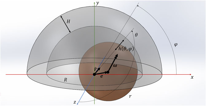
The spherical joint comprises the ball, i.e., a solid sphere of radius
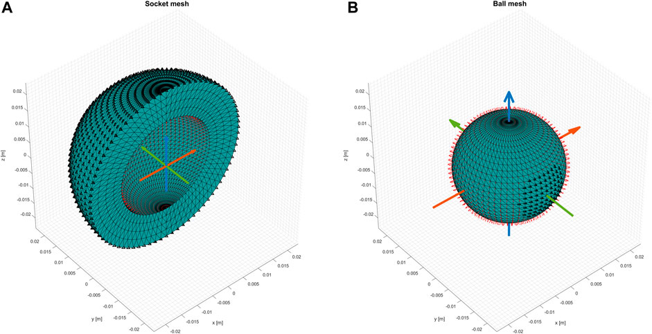
With reference to a previous work of the same authors (Ruggiero and Sicilia, 2021), the linear tetrahedra mesh was created for both the bodies and is shown in Figure 1, where the fixed nodes are highlighted by black triangles and the pressure loaded nodes are identified by red arrows oriented toward the radial loading direction. The pressure vector acts simultaneously on the internal socket surface and external ball surface, while the socket is fixed on the external surface and the ball is characterized by fixed nodes with the
With the developed approach (Ruggiero and Sicilia, 2021), the equilibrium equation associated with the linear elastic mechanical behavior of the two structures is converted in Eq. 2 into the relationship which links the surface radial deformation vector
As described next, the Reynolds lubrication equation refers to a surface grid domain fixed with the socket's internal surface, so, while the constitutive Eq. 2 referring to the socket does not need further transformations, the one referring to the ball has to be rotated. The rotation is obtained through the cubic interpolation matrices
Then, writing Eq. 2 for both the spherical joint bodies and rotating all the involved quantities in the socket’s internal surface grid through Eq. 3, the final constitutive deformation model which relates to the total surface deformation vector
The Elasto-Hydrodynamic Lubrication Model
Under the classical hypotheses, the unsteady Reynolds equation is reported in its general form in Eq. 5: it is a partial differential equation in which the lubricant pressure
The quantities involved in the Reynolds equation are characterized by the following (Ruggiero and Sicilia, 2020b), considering that the spatial coordinates related to the analyzed spherical contact are referred to the spherical angles
The rheological properties are considered as functions of the pressure through:
1) The Dowson–Higginson density model in Eq. 6, in which it is assumed that the lubricant density
2) The product between the cross non-Newtonian model and the Barus one in Eq. 7, which consider, respectively, that the lubricant viscosity
The sub-models described in the Eqs 6, 7 are very useful in the context of the biomechanical tribological pairs represented by the artificial hip joint, in which the high pressure level reached within the gap could be responsible for an appreciable increase of the synovial fluid density, while the low relative angular speed causes the aggregation of the macromolecules composing the fluid, generating a considerable increase in its viscosity.
The surfaces’ separation
1) the geometrical approach
2) the total surfaces’ radial deformation field
3) the penetration wear depth field
The entraining velocity vector
Once all the quantities involved in the Reynolds equation have been identified, it is reported in Eq. 10, turned in to spherical coordinates, and coupled with the boundary pressure
Eq. 10 is discretized with the finite differences on the socket’s internal surface grid by the definition of some groups, vectors and matrices explained in the authors’ previous work. The objective is to write the Reynolds equation
Even though the analytical forms of all the quantities involved in the Reynolds equation are known, from a numerical point of view, it is not convenient to use the Newton iterative method to solve the system Eq. 11 as done in Ruggiero and Sicilia (2020b), because the related Jacobian matrix in this case is a full matrix due to the presence of all the non-zero elements belonging to the influence matrix
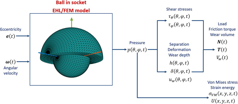
The working algorithm logic is shown in Figure 3 and is supplied by the input data of eccentricity
Once the lubrication algorithm has reached convergence over all the analyzed time periods, the interesting integral quantities of load, friction torque, and wear volume can be evaluated. The load vector over time
The friction torque vector calculation requires the knowledge of the shear stress fields due to the lubricant acting on the socket internal surface; they are collected in vector
Then, the friction torque vector
Finally, the wear volume loss over time
As stated during the finite element deformation model description, additional interesting information about the entire tribo-system body is achieved by returning to the mechanical equilibrium reported in Eq. 2, that is, the solution of the elasto-hydrodynamic lubrication problem provides the time evolution of the lubricant pressure vector
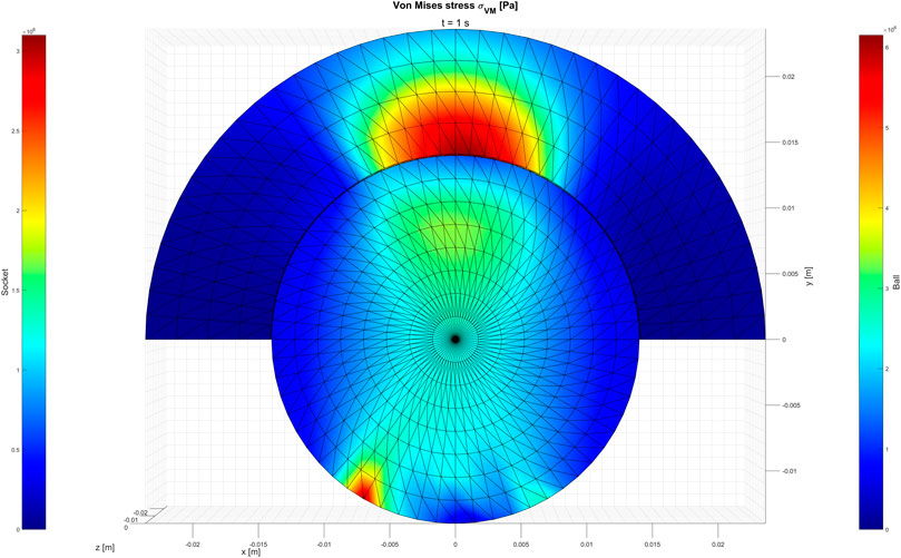
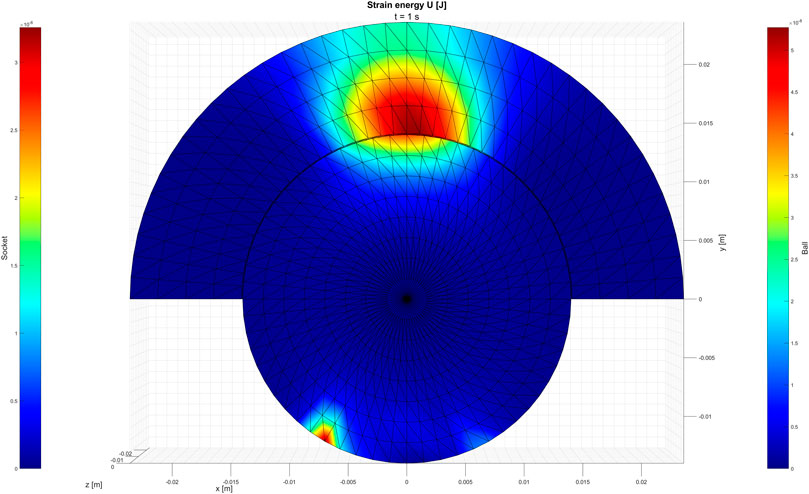
The two fields over time evaluated in this work are the Von Mises equivalent stress
The whole merged model flowchart is shown in Figure 4, in which all the input and output quantities are highlighted.
Results and Discussions
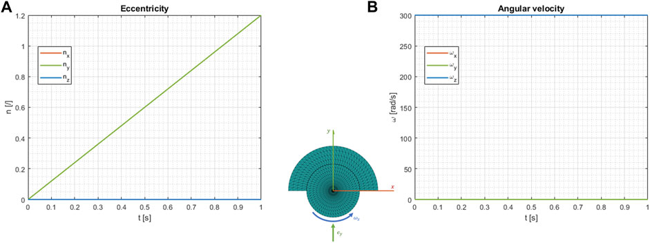
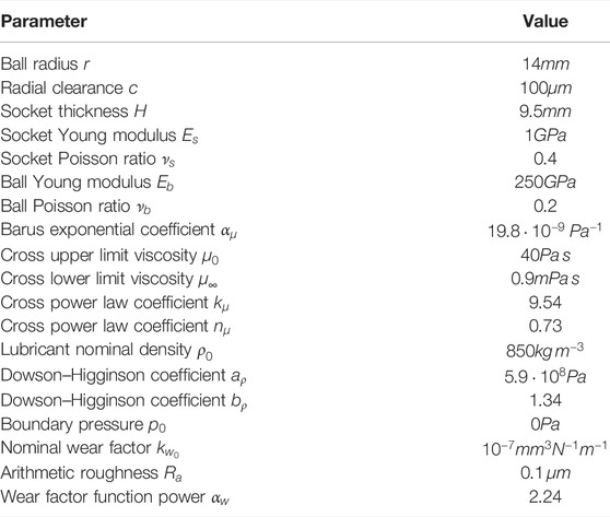
The developed elasto-hydrodynamic lubrication simulator was tested for a typical biotribological system considered in the human total joint replacements: a Ceramic ball in an ultra-high-molecular-weight-polyethylene (UHMWPE) socket. The joint kinematics was selected, without loss of generality, as a planar motion (Figure 5) in the
The tribological quantities' output are shown in their following dimensionless form, by using the maximum Hertzian pressure and shear stress
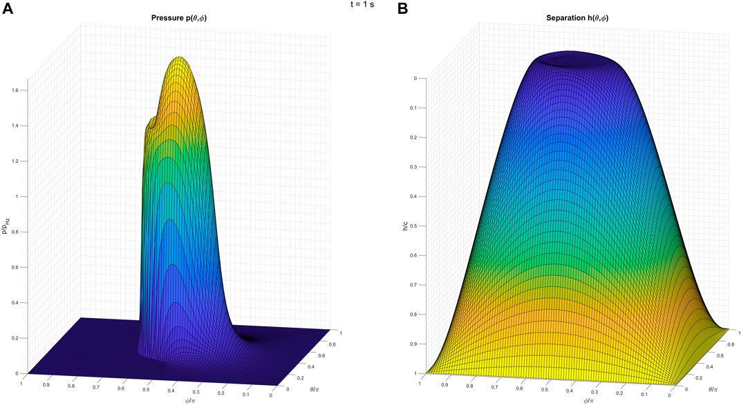
The calculated fluid pressure
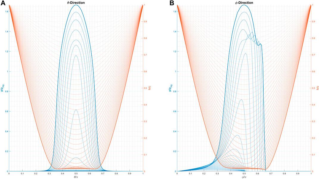
The classical elasto-hydrodynamic profiles of the pressure and separation are better visualized in Figure 7, showing the complete time evolution of the same quantities depicted in Figure 6; here, they are reported in correspondence with the pressure peak position, in which each line is characterized by proportional transparency going from 100% to 0% along with time. Due to the only relative rotational motion around the
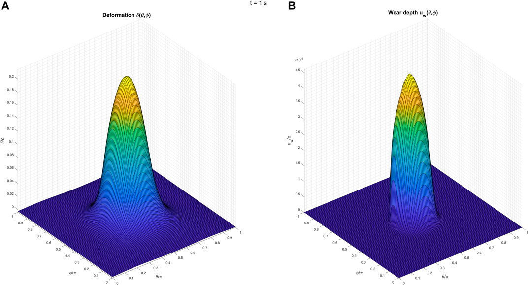
During the analyzed time instant, the fields of the surface radial deformation
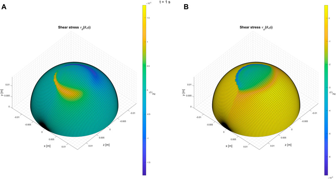
The shear stress fields are shown in Figure 9 and in Supplementary Video S4 over the socket's internal surface domain, in order to analyze their action in terms of friction; the shear stress acting along the
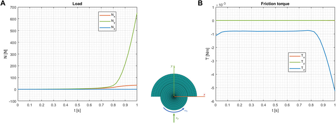
The integration over the socket surface of the pressure and of the shear stress led to the time evolution of load
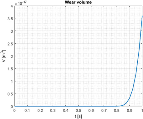
The surface integration over the analyzed domain of the penetration wear depth shown in the Figure 8 causes the wear volume loss time evolution reported in Figure 11.
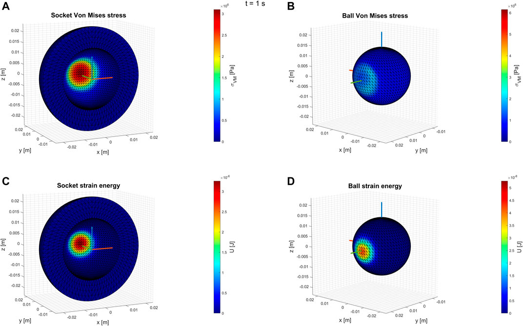
The quantities describing the mechanical behavior of the spherical joint with respect to the analyzed kinematics can be viewed both for the entire body and for its internal structure. In particular, the Von Mises stress and the strain energy fields are depicted in Figure 12 in correspondence to the last time instant for both the ball and socket, by viewing the contact interface (the complete time evolution of the visualized quantities is available in Supplementary Video S5); on the contacting surfaces, the socket is characterized by higher values of both Von Mises stress and strain energy than the ball because of its lower stiffness; in general, the ball is more loaded on its back (negative
The same quantities referring to the internal structure of the spherical joint are shown, respectively, in Figures 13, 14, highlighting their propagation inside the bodies in the
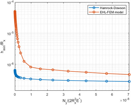
The reliability of the model was discussed by comparing the minimum fluid meatus thickness
where the viscosity surface integral mean
The comparison is depicted in Figure 15, where the minimum fluid meatus thickness is plotted against the vertical load
Conclusion
The objective of this work was to integrate a finite element deformation model already developed by the authors into an elasto-hydrodynamic lubrication algorithm, in order to characterize the deformation of the surfaces belonging to the analyzed tribo-system through a complex and accurate fluid–solid interaction tool.
The mechanical and tribological behavior of the ball in socket joint was discussed and described through the analytical theories coming from the Reynolds equation and the finite element method in the case of linear elastic materials.
In particular, the surface deformation model referred to the spherical geometry of the ball and socket bodies and, starting from the mechanical equilibrium which links the nodal displacements to the nodal forces through the stiffness matrix, led to the definition of the influence matrix which directly related the total surfaces’ radial deformation to the pressure established within the interface between the ball and the socket; following the proposed approach, the interfacial influence matrix contains information about the mechanical and geometrical properties of the whole body comprising the spherical joint and, furthermore, the finite element model allows analyses of the tensional state of the global structure once the lubrication algorithm has elaborated the interfacial lubricant pressure.
The evaluated deformation directly communicates to the summation which composes the surfaces’ separation that is needed to solve the Reynolds equation referred to the elasto-hydrodynamic mode. The lubricant rheology properties of density and dynamical viscosity are defined as pressure functions and the viscosity, moreover, is considered as a function of the lubricant shear rate in order to simulate its non-Newtonian shear-thinning or -thickening behavior. The surface separation geometry varies over time even because its composition accounts for a loss contribution equal to the penetration wear depth, which is updated over each time instant. The resulting highly nonlinear partial differential equation is discretized over the socket’s internal surface through the finite differences and solved by an iterative technique. The lubricant pressure solution due to the relative motion input in terms of eccentricity and angular velocity of the ball with respect to the socket is used to evaluate the shear stress acting on the socket surface, then the integral quantities of load, friction torque, and wear volume are elaborated. Thanks to the used finite element deformation model, the Von Mises stress and the strain energy related to the spherical joint bulk are computed by the knowledge of the nodal displacements.
The developed algorithm related to the integration of the two described models is written in a MATLAB environment, and it is used to analyze the elaborated output quantities referred to as a ceramic-in-UHMWPE spherical joint during a basic planar motion. The results computed by the model reproduced the classical elasto-hydrodynamic shapes referring to the lubricant pressure and to the surface separation, which presented the pressure spike in correspondence to the minimum film thickness and provided the time evolution of the load lying in the relative motion plane and of the friction torque consistent with the allowed relative rotation, showing a good computational behavior, demonstrated by the comparison with the Hamrock–Dowson model. Furthermore, the propagation of the lubricant pressure action along with the ball and socket both superficial and sub-superficial structures was visualized in terms of Von Mises stress and strain energy, providing information about the modality to absorb the stress of the materials involved in the construction of the spherical joint.
Due to the high information content provided by the developed model, it could be exploited in the framework of the tribological characterization or design of lubricated joints for both mechanical and biomechanical purposes (e.g., the total hip replacements). From a purely mechanical point of view, a Stribeck curve describing the friction coefficient in correspondence with a chosen kinematics can be depicted, in order to, for example, define a map that can compute the friction torque due to the ball and socket relative motion and loading configurations, which could be very useful within the multibody simulation algorithms. In order to reach more accurate results, the main improvements in the authors’ perspective could regard
1) the adaptation of the entire model to the mixed lubrication regime, dividing the socket's internal surface into lubricated areas and direct contact zones;
2) the introduction of a damping matrix within the finite element model, in order to consider the possibility of having a viscoelastic mechanical behavior;
3) the coupling of the Reynolds equation to the energy conservation equation, such that the computed interfacial temperature field could be used to define a further contribution to the nodal forces due to the consequent thermal expansion of the finite elements.
Data Availability Statement
The original contributions presented in the study are included in the article/Supplementary Material, further inquiries can be directed to the corresponding author.
Author Contributions
AR: conceptualization, formal analysis, methodology, supervision, reviewing and editing, and funding. AS: formal analysis, programming, calculations, writing—original draft, and writing—reviewing, and editing.
Funding
This research was funded by MIUR, PRIN 2017 BIONIC.
Conflict of Interest
The authors declare that the research was conducted in the absence of any commercial or financial relationships that could be construed as a potential conflict of interest.
Publisher’s Note
All claims expressed in this article are solely those of the authors and do not necessarily represent those of their affiliated organizations, or those of the publisher, the editors, and the reviewers. Any product that may be evaluated in this article, or claim that may be made by its manufacturer, is not guaranteed or endorsed by the publisher.
Supplementary Material
The Supplementary Material for this article can be found online at: https://www.frontiersin.org/articles/10.3389/fmech.2022.909156/full#supplementary-material
References
Askari, E., and Andersen, M. S. (2018). A Closed-form Formulation for the Conformal Articulation of Metal-On-Polyethylene Hip Prostheses: Contact Mechanics and Sliding Distance. Proc. Inst. Mech. Eng. H. 232 (12), 1196–1208. doi:10.1177/0954411918810044
Evans, H. P., and Hughes, T. G. (2000). Evaluation of Deflection in Semi-infinite Bodies by a Differential Method. Proc. Institution Mech. Eng. Part C J. Mech. Eng. Sci. 214 (4), 563–584. doi:10.1243/0954406001523911
Fregly, B. J., Bei, Y., and Sylvester, M. E. (2003). Experimental Evaluation of an Elastic Foundation Model to Predict Contact Pressures in Knee Replacements. J. biomechanics 2003 (36), 1659–1668. doi:10.1016/s0021-9290(03)00176-3
Gao, L., Dowson, D., and Hewson, R. W. (2016). A Numerical Study of Non-newtonian Transient Elastohydrodynamic Lubrication of Metal-On-Metal Hip Prostheses. Tribol. Int. 93, 486–494. doi:10.1016/j.triboint.2015.03.003
Gao, L., Dowson, D., and Hewson, R. W. (2017). Predictive Wear Modeling of the Articulating Metal-On-Metal Hip Replacements. J. Biomed. Mat. Res. 105 (3), 497–506. doi:10.1002/jbm.b.33568
Gao, L., Wang, F., Yang, P., and Jin, Z. (2009). Effect of 3D Physiological Loading and Motion on Elastohydrodynamic Lubrication of Metal-On-Metal Total Hip Replacements. Med. Eng. Phys. 31 (6), 720–729. doi:10.1016/j.medengphy.2009.02.002
Halloran, J. P., Easley, S. K., Petrella, A. J., and Rullkoetter, P. J. (2005). Comparison of Deformable and Elastic Foundation Finite Element Simulations for Predicting Knee Replacement Mechanics. J. Biomech. Eng. 127, 813–818. doi:10.1115/1.1992522
Hamrock, B. J., and Dowson, D. (1976). Isothermal Elastohydrodynamic Lubrication of Point Contacts: Part III – Fully Flooded Results. Cleveland, OH: National Aeronautics and Space Administration Technical Note.
Jagatia, M., and Jin, Z. M. (2001). Elastohydrodynamic Lubrication Analysis of Metal-On-Metal Hip Prostheses under Steady State Entraining Motion. Proc. Inst. Mech. Eng. H. 215 (6), 531–541. doi:10.1243/0954411011536136
Jalali-Vahid, D., Jagatia, M., Jin, Z. M., and Dowson, D. (2001). Prediction of Lubricating Film Thickness in a Ball-In-Socket Model with a Soft Lining Representing Human Natural and Artificial Hip Joints. Proc. Institution Mech. Eng. Part J J. Eng. Tribol. 215 (4), 363–372. doi:10.1243/1350650011543600
Jalali-Vahid, D., Jin, Z. M., and Dowson, D. (2003). Elastohydrodynamic Lubrication Analysis of Hip Implants with Ultra High Molecular Weight Polyethylene Cups under Transient Conditions. Proc. Institution Mech. Eng. Part C J. Mech. Eng. Sci. 217 (7), 767–777. doi:10.1243/095440603767764417
Jalali-Vahid, D., and Jin, Z. M. (2001). Transient Elastohydrodynamic Lubrication Analysis of Ultra-high Molecular Weight Polyethylene Hip Joint Replacements. Proc. Institution Mech. Eng. Part C J. Mech. Eng. Sci. 216 (4), 409–420. doi:10.1243/0954406021525205
Lubrecht, A. A., Venner, C. H., and Colin, F. (2009). Film Thickness Calculation in Elasto-Hydrodynamic Lubricated Line and Elliptical Contacts: The Dowson, Higginson, Hamrock Contribution. Proc. Institution Mech. Eng. Part J J. Eng. Tribol. 223 (3), 511–515. doi:10.1243/13506501jet508
Mattei, L., Di Puccio, F., Piccigallo, B., and Ciulli, E. (2011). Lubrication and Wear Modelling of Artificial Hip Joints: A Review. Tribol. Int. 44 (5), 532–549. doi:10.1016/j.triboint.2010.06.010
Mukras, S. M., Kim, N. H., Schmitz, T. L., and Sawyer, W. G. (2010). Evaluation of Contact Force and Elastic Foundation Models for Wear Analysis of Multibody Systems. Int. Des. Eng. Tech. Conf. Comput. Inf. Eng. Conf. 44106, 1565–1577. doi:10.1115/detc2010-28750
Pèrez-Gonzàlez, A., Fenollosa-Esteve, C., Sancho-Bru, J. L., Sànchez-Marìn, F. T., and Vergara, M. a. R.-C. P. J. (2008). A Modified Elastic Foundation Contact Model for Application in 3D Models of the Prosthetic Knee. Med. Eng. Phys. 30 (3), 387–398.
Ruggiero, A., D’Amato, R., and Affatato, S. (2019). Comparison of Meshing Strategies in THR Finite Element Modelling. Materials 12 (14), 2332. doi:10.3390/ma12142332
Ruggiero, A., Merola, M., and Affatato, S. (2018). Finite Element Simulations of Hard-On-Soft Hip Joint Prosthesis Accounting for Dynamic Loads Calculated from a Musculoskeletal Model during Walking. Materials 11 (4), 574. doi:10.3390/ma11040574
Ruggiero, A., and Sicilia, A. (2020b). A Mixed Elasto-Hydrodynamic Lubrication Model for Wear Calculation in Artificial Hip Joints. Lubricants 8 (7), 72. doi:10.3390/lubricants8070072
Ruggiero, A., and Sicilia, A. (2020c). A Novel Explicit Analytical Multibody Approach for the Analysis of Upper Limb Dynamics and Joint Reactions Calculation Considering Muscle Wrapping. Appl. Sci. 10 (21), 7760. doi:10.3390/app10217760
Ruggiero, A., Sicilia, A., and Affatato, S. (2020). In Silico total Hip Replacement Wear Testing in the Framework of ISO 14242-3 Accounting for Mixed Elasto-Hydrodynamic Lubrication Effects. Wear 460, 203420. doi:10.1016/j.wear.2020.203420
Ruggiero, A., and Sicilia, A. (2020a). Lubrication Modeling and Wear Calculation in Artificial Hip Joint during the Gait. Tribol. Int. 142, 105993. doi:10.1016/j.triboint.2019.105993
Ruggiero, A., and Sicilia, A. (2021). Mathematical Development of a Novel Discrete Hip Deformation Algorithm for the In Silico Elasto-Hydrodynamic Lubrication Modelling of Total Hip Replacements. Lubricants 9 (4), 41. doi:10.3390/lubricants9040041
Shettar, B. M., Hiremath, P., and Bujurke, N. (2018). A Novel Numerical Scheme for the Analysis of Effects of Surface Roughness on EHL Line Contact with Couple Stress Fluid as Lubricant. Sadhana 43 (8), 1–12. doi:10.1007/s12046-018-0906-y
Srivastava, G., Christian, N., and Fred Higgs, C. (2021). A Predictive Framework of the Tribological Impact of Physical Activities on Metal-On-Plastic Hip Implants. Biotribology 25, 100156. doi:10.1016/j.biotri.2020.100156
van Leeuwen, H. (2009). The Determination of the Pressure-Viscosity Coefficient of a Lubricant through an Accurate Film Thickness Formula and Accurate Film Thickness Measurements. Proc. Institution Mech. Eng. Part J J. Eng. Tribol. 223 (8), 1143–1163. doi:10.1243/13506501jet504
Wang, F. C., Jin, Z. M., McEwen, H. M. J., and Fisher, J. (2003). Microscopic Asperity Contact and Deformation of Ultrahigh Molecular Weight Polyethylene Bearing Surfaces. Proc. Inst. Mech. Eng. H. 217 (6), 477–490. doi:10.1243/09544110360729117
Wang, F. C., and Jin, Z. M. (2004a). Prediction of Elastic Deformation of Acetabular Cups and Femoral Heads for Lubrication Analysis of Artificial Hip Joints. Proc. Institution Mech. Eng. Part J J. Eng. Tribol. 218 (3), 201–209. doi:10.1243/1350650041323331
Wang, F., and Jin, Z. (2004b). Lubrication Modelling of Artificial Hip Joints: From Fluid Film to Boundary Lubrication Regimes. Eng. Syst. Des. Analysis 417731, 605–611. doi:10.1115/esda2004-58077
Wang, F., and Jin, Z. (2008). Transient Elastohydrodynamic Lubrication of Hip Joint Implants. J. Tribol. 130, 6200. doi:10.1115/1.2806200
Wang, W.-Z., Wang, F.-C., Jin, Z.-M., Dowson, D., and Hu, Y.-Z. (2009). Numerical Lubrication Simulation of Metal-On-Metal Artificial Hip Joint Replacements: Ball-In-Socket Model and Ball-On-Plane Model. Proc. Institution Mech. Eng. Part J J. Eng. Tribol. 223 (7), 1073–1082. doi:10.1243/13506501jet581
Nomenclature
Abbreviations
Keywords: EHD lubrication, finite element method, ball in socket, fluid film thickness, fluid–solid interaction system
Citation: Ruggiero A and Sicilia A (2022) Implementation of a Finite Element Deformation Model Within an Elasto-Hydrodynamic Lubrication Numerical Solver for a Ball in Socket Tribopair. Front. Mech. Eng 8:909156. doi: 10.3389/fmech.2022.909156
Received: 31 March 2022; Accepted: 03 May 2022;
Published: 08 June 2022.
Edited by:
Giuseppe Carbone, Politecnico di Bari, ItalyReviewed by:
Gananath Doulat Thakre, Indian Institute of Petroleum (CSIR), IndiaEmanuel Willert, Technical University of Berlin, Germany
Copyright © 2022 Ruggiero and Sicilia. This is an open-access article distributed under the terms of the Creative Commons Attribution License (CC BY). The use, distribution or reproduction in other forums is permitted, provided the original author(s) and the copyright owner(s) are credited and that the original publication in this journal is cited, in accordance with accepted academic practice. No use, distribution or reproduction is permitted which does not comply with these terms.
*Correspondence: Alessandro Sicilia, YXNpY2lsaWFAdW5pc2EuaXQ=
 Alessandro Ruggiero
 Alessandro Sicilia