- 1College of Electronics and Information Engineering, Shenzhen University, Shenzhen, China
- 2School of Integrated Circuits and Electronics, Beijing Institute of Technology, Beijing, China
In this paper, we proposed an ultrafast and nanoscale hot-wire flow (NHF) sensor implemented in a 0.18 µm complementary metal-oxide-semiconductor microelectromechanical system (CMOS-MEMS) technology. The nanoscale wire was released and reduced in thickness and width by an in-house developed post-CMOS fabrication process, hence the heat conduction loss is greatly suppressed, while the response time of the NHF sensor is significantly improved. Benefiting from the nano size of the hot-wire (a width of 622 nm), the NHF sensor exhibits an ultrafast response time of 30 µs (@ airflow velocity of 0 m/s), a wide flow range of 0–30 m/s, and a cut-off frequency of 21 kHz under the constant temperature (CT) mode. In addition, an equivalent circuit model (ECM) was established in PSPICE to predict the NHF sensor performance, and the theoretical simulation results were in good agreement with the experiment results.
Introduction
MEMS technology has grown rapidly over the past few decades (Kuo et al., 2012), and its rise can be traced back to the inspiration of Feynman’s lecture in 1961 (Feynman, 1992). The main purpose of MEMS is to pursue the smaller device sizes, lower costs, and higher performance. CMOS-MEMS technology has been recognized as one of the most effective ways to realize low-cost miniaturized devices due to its highly integrated capabilities. As a result, research interest in CMOS-MEMS combined technique has increased dramatically. Based on the sequence of CMOS and MEMS process, CMOS-MEMS technologies can be classified into three categories: pre-CMOS, intra-CMOS, and post-CMOS (Qu, 2016). In pre-CMOS technology, MEMS structures are defined and embedded in advance on silicon wafers (Qu, 2016). While for intra-CMOS technology, CMOS process steps are intertwined with additional thin films deposition and micromachining steps to form MEMS structures (Kuehnel and Sherman, 1994). Compared to the above-mentioned two technologies, post-CMOS technology is more attractive due to its excellent accessibility and compatibility with IC foundries. In post-CMOS, all MEMS process steps are performed after CMOS fabrication is completed (Qu, 2016). Of these, post-CMOS technology was first utilized in the fabrication of a silicon-based pressure sensor by Borky et al. in the 1970s (Borky and Wise, 1979).
As one of the important devices realized in MEMS technology, MEMS flow sensors are essential for various applications (Qiu et al., 1996), such as biomedical (Gray et al., 2018), microfluidics (Wang et al., 2009), energy-efficient building (Fisk and De Almeida, 1998; Miao et al., 2014), and so on. In general, micromachined flow sensors can be classified as either thermal or non-thermal (Kuo et al., 2012). Specifically, thermal flow sensors are widely investigated, due to their simple structure and low power consumption (Kuo et al., 2012). According to the thermal interaction between the sensors and the fluids, thermal flow sensor can be classified into three types: hot-film/hot-wire flow sensors (Comte-Bellot, 1976; Mailly et al., 2001), time-of-flight flow sensors (Byon, 2015), and calorimetric flow sensors (Kitsos et al., 2019). All types of micro thermal flow sensors can be easily implemented in CMOS processes thanks to their non-movable sensing structures. To this end, researchers have recently tried to implement cost-effective thermal flow sensors by using mature CMOS-MEMS technology. For example, Miao et al. (Miao et al., 2014) reported a hot-wire flow sensor that developed in a 0.35 μm 2P4M CMOS-MEMS technology. The developed hot-wire sensor with a size of 300 μm × 2 μm × 3.76 μm, achieving a sensitivity of 23.87 mV/(m/s) and a heating power of around 0.79 mW. After that, Xu et al. (Xu et al., 2020) also designed and fabricated a thermoresistive micro calorimetric flow (TMCF) sensor by using a 0.35 μm node CMOS-MEMS technology, and their sensor gained a prominent normalized sensitivity of 228 µV/(m/s)/mW for the airflow.
Generally, the basic characteristics that reflect the performance of thermal flow sensors are response time, sensitivity, flow range, etc. Although the calorimetric flow sensor shows the highest sensitivity and bidirectional flow detection capability, it requires two or more symmetrically arranged temperature-sensitive elements, which results in high sensor complexity and long response times (Kohl et al., 2007; Kuo et al., 2012). For the time-of-flight flow sensor, a high-energy thermal pulse for the microheater is needed so that a distinct peak signal can be detected from downstream (Berthet et al., 2011; De Luca and Udrea, 2017). For the hot-wire/hot-film flow sensor, convective heat loss from a single thin wire/film (often referred to as a heater), can be used to determine the flow (Heyd et al., 2010). Meanwhile, by placing the hot-wire on a low-thermal conductivity membrane and operating in constant temperature (CT) mode (Nguyen, 1997; Chen and Chang Liu, 2003), the flow range and response time of the hot-wire/hot-film flow sensor can be significantly improved (Mehmood et al., 2019).
Typically, the response time of thermal flow sensors is in the range of several hundreds of µs to several ms (Elwenspoek, 1999; Buchner et al., 2006; Sosna et al., 2011). For example, Xu et al. (Xu et al., 2022) proposed a CMOS-MEMS calorimetric flow sensor with a high sensitivity of 453 mV/(m/s), and its response time was demonstrated as 4.8 ms. However, this extremely long time constant will limit the application of micro flow sensor in fields requiring fast response (Verhoeven and Huijsing, 1996). For example, the air intake of a car engine typically needs to change from a positive flow condition to a negative flow condition in less than 5 ms (Sosna et al., 2011). Otherwise, large delays in gas flow sensing will result in intermittent engine stalls. Moreover, turbulence measurements usually require fast frequency responses above several kHz to measure velocity fluctuations at ultra-small scales (Bailey et al., 2010). In general, a common strategy to achieve a fast response time for the thermal flow sensor is to scale down the sensing elements and isolate them from the substrate (Balakrishnan et al., 2018).
With the help of MEMS technology, the response time of micro thermal flow sensors can be shortened with the reduced sensor size (Kunkel et al., 2006). This scaling benefit is also applicable to the highly integrated CMOS-MEMS sensor. However, to the best of our knowledge, most reported CMOS-MEMS thermal flow sensors are still on the microscale. More efforts should be taken to pursue a smaller sensor size and faster dynamic response. In this paper, we proposed a nanoscale hot-wire flow (NHF) sensor by using a 0.18 µm complementary metal-oxide-semiconductor microelectromechanical system (CMOS-MEMS) technology. The NHF sensor is released from the silicon substrate through an in-house developed post-CMOS fabrication process, while the width and thickness of the sensing wire is significantly reduced. Thereby, this NHF sensor shows a short response time of 30 µs, a wide cut-off frequency of 21 kHz, and a measurable flow range of 0–30 m/s in CT mode. Furthermore, an equivalent circuit model (ECM), which for heat transfer and interface circuit coupling simulation, is established in PSPICE to rapidly predict the sensor performance, including steady sensor output, response time, and cut-off frequency. The analytical results provided by the ECM are in good agreement with the experimental data.
Design and Fabrication
Theoretical Analysis
The proposed nanoscale hot-wire flow (NHF) sensor utilizes its cooling effect from the forced convection to detect fluid flow (Tai and Muller, 1988), as shown in Figure 1A. The NHF sensor consists of only a hot-wire that is released from the Si substrate. It is worth noting that its width is nanoscale. Two different operation modes are commonly used for the electrical configuration of the microheater: CC (constant current) mode and CT (constant temperature) mode. Compared with CC mode, although CT mode requires more complex circuitry, it can significantly shorten the response time of the flow sensor (Jiang et al., 1994; Shikida et al., 2009; Zhao, 2020). For the configuration of the NHF sensor in CT mode, a negative feedback circuit consisting of a Wheatstone bridge and an operational amplifier is used (Shikida et al., 2009; Zhao, 2020), as shown in Figure 1B. The hot wire Rh is placed in a quarter bridge and serves as both a heater and a sensor. In addition, R1, R2, and Rs are off-chip resistors. When the fluid flow over the microheater increases, the resistance of Rh is decreased due to the cooling effect. As a result, an increased voltage difference is formed at the input ends of the operational amplifier, which causes an enhanced voltage to be fed into the Wheatstone bridge. With the increased heating power, the resistance of microheater Rh increases, and the Wheatstone bridge balances again. The power consumption required to maintain the constant temperature under different flow velocities is monitored and used to determine the flow velocity.
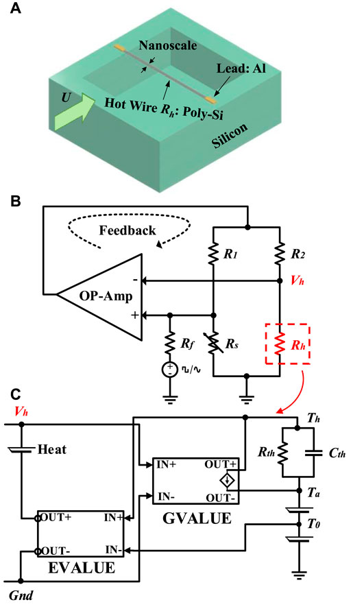
FIGURE 1. (A) The schematic of the NHF sensor. (B) The CT control circuit for the NHF sensor. (C) The established ECM of the NHF sensor in PSPICE.
When the Wheatstone bridge is balanced, the differential mode voltage is almost equal to zero. Thus,
With the positive temperature coefficient of resistance (TCR) of Rh, we have:
where Rh0 is the resistance of the microheater at the temperature of T0, Rh is the resistance of the microheater at the working temperature of Th, α is the TCR of Rh.
According to Eqs 1 and 2, the constant temperature of the microheater can be calculated as:
Eq. 3 demonstrates that the microheater can be operated in different constant temperatures by setting the ratio of R1/R2 and the resistance of Rs.
To understand the mechanical-thermal-electrical coupling behavior of the NHF sensor, it is necessary to build an equivalent circuit model of the microheater in the CT mode. The relationship between the power consumption of the microheater and the flow velocity is given by the King’s law (King, 1914; Bruun et al., 1988):
where A is the heat loss that takes the conduction, radiation, and free convection into account, and it is not a function of U. BUn represents forced convection by the boundary layer flow, and the exponent n is a constant value that depends on the sensor structure.
Based on energy conservation, we have (Xu, 2017):
where ρheater, Cheater, and Vheater are the density, heat capacity, and volume of the NHF sensor, and t is time.
Thus, the equivalent circuit model (ECM) of microheater could be established in PSPICE, as shown in Figure 1C. Cthermal is the thermal capacitance and Rthermal is the thermal resistance as expressed in Eqs 6 and 7, respectively. More details on simulating sensor performance with this ECM model are described in the Supplementary Material.
Sensor Fabrication
The sensor chip is prepared by the GlobalFoundries 0.18 μm 1P6M CMOS process. Typically, a high temperature coefficient of resistance (TCR) is desired for a thermal sensing material since the sensitivity to temperature change is proportional to a material’s TCR (Kuo et al., 2012; Balakrishnan et al., 2018). Besides, the resistivity of the sensing material should be taken into account because it is the change in resistance that is detected (Kuo et al., 2012). Thereby, in consideration of the relatively high TCR and resistivity values, polysilicon is chosen as the sensing material of the NHF sensor.
For the microfabrication of the NHF sensor, an in-house developed post-CMOS process is further adopted, as shown in Figure 2. First, the sensor chip prepared by the CMOS process is glued on a 4-inch Si wafer with a spin-coated photoresist (Figure 2A). Second, a 4 μm thick AZ9260 photoresist is deposited on the sensor chip through a spray coating process, and then the photolithography is performed with a MEMS opening size of 200 μm × 400 μm (Figure 2B). Next, the oxide reactive ion etching (RIE) is conducted to form the microstructure of the NHF sensor (Figure 2C). A vacuum pressure of 68 mT and a bias power of 85 W were used in the detailed RIE recipe, and the flow rates of O2 and CHF3 were controlled at 1.5 sccm and 87 sccm, respectively. Notably, the thickness of the NHF sensor can be controlled by choosing different aluminum layers as etch stops. Since reducing the thickness of the NHF sensor will suppress the heat conduction loss, the second layer of metal is used here as an etch stop. When this step is complete, the metal-based etch stop layer is removed (Figure 2D). Then, several Si trenches with a depth of 80 μm are defined through the deep RIE (Figure 2E). Finally, the NHF sensor is released from the Si substrate by XeF2 isotropic Si etching (Figure 2F), and the depth of the bottom cavity is increased to about 100 μm.
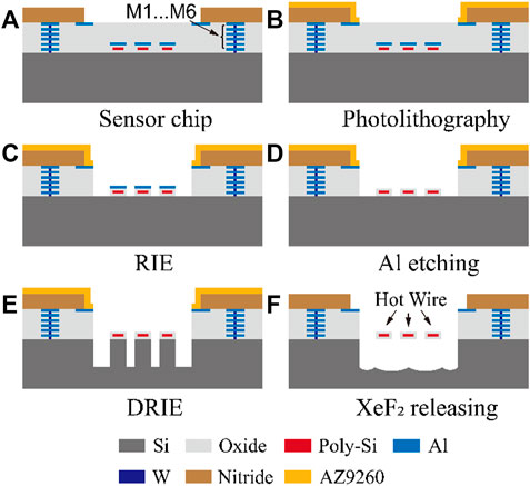
FIGURE 2. The in-house developed post-CMOS fabrication steps for the NHF sensor. (A) Chip fabricated by CMOS technology. (B) Photolithography. (C) Oxide etching by RIE. (D) Al etching. (E) Si trench structure by DRIE. (F) XeF2 releasing and PR removing.
Figure 3 shows a microphotograph of the fabricated NHF sensor, where the 0.18 µm wide and 0.2 µm thick conductive polysilicon layer is surrounded by silicon oxide. For the detail of the NHF sensor, the resistance of the released 200 μm × 622 nm × 2.7 μm (Length × Width × Thickness) wire is 6087 Ω at 25°C. It is worth noting that the width of the sensing wire is successfully shrunk down to the nanometer level by the in-house developed post-CMOS process. However, the CMOS-MEMS fabrication process and the mechanical strength of materials limit the minimum width of the hot wire. For example, the standard 0.18 µm CMOS process offered by the GlobalFoundries specifies a minimum width of 0.23 μm for the adopted etch stop layer of Metal 2 layer. Besides, considering the possible over-etching issue in the post-CMOS process, a proper allowance should be designed around polysilicon. More importantly, the finite element method (FEM) simulation shows that a 0.18 µm wide wire may break under the worst wind load condition @ 30 m/s, where the observed 370 MPa tensile stress exceeds the yield stress of the oxide. Therefore, a sensing wire that is too narrow in this CMOS-MEMS process may limit its measurable flow range and reliability. In this paper, the fabricated 622 nm wide wire that contained a 0.18 µm wide polysilicon shows good mechanical reliability as proved by static structural analysis in FEM simulation.
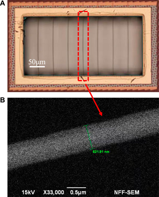
FIGURE 3. (A) The optical graph of the fabricated NHF sensor by using a 0.18 μm 1P6M CMOS-MEMS technology. (B) The SEM micrograph of the NHF sensor. The width of the sensor is 622 nm.
Experimental Method
The NHF sensor is embedded in a printed circuit board (PCB) and packaged in a flow channel with a cross-section of 15 mm2, as shown in Figure 4A. Figure 4B shows the CT control circuit for the NHF sensor by using PCB technology. An LM358 device with an open-loop gain of 100 dB is used as the negative feedback operational amplifier, and the supply voltage is 5 V. In addition, the ratio of R1/R2 is set as 5/1 and the resistance of Rs is set as 35 kΩ. Thus, the overheat temperature of the nano hot-wire flow sensor is determined as 62 K.
So far, a number of research works on the dynamic response of thermal flow sensors have been reported (Jiang et al., 1994; Chen and Chang Liu, 2003). However, due to the complexity of the perfectly generated fluid steps, rigorous measurement of the sensor response time is not that easy. Kohl et al. (Kohl et al., 2003) placed a thermal flow sensor into a pipe and used a bursting balloon to generate a sharply changed fluid step for the measurement of the sensor time constant. But this testing setup causes acoustic oscillations at 680 Hz superimposed with the flow signal (Ashauer et al., 2001). To overcome this shortcoming, (Sosna et al., 2011) utilized a complicated experimental device including a membrane and a loudspeaker to create a flow step. Given that it is difficult to generate a well-defined fluid velocity step, the electrical method is used for the time constant measurement commonly. In this paper, as shown in Figure 1B, a square or a sine wave in series with a 750 kΩ resistor Rr is applied to the non-inverting input of the amplifier, and the response time and cut-off frequency of the NHF sensor are determined from the output voltage Vh. Notably, both the square wave and the sine wave have a bias voltage of 1 V and a peak-to-peak voltage of 400 mV.
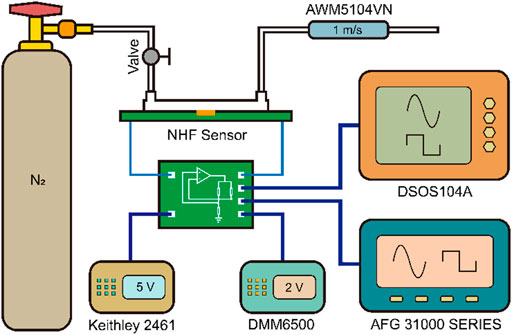
Figure 5 shows the testing system built for the NHF sensor. The N2 flow is controlled by a valve and a commercial flow meter (AWM5104VN, Honeywell, United States) is used as a reference. In addition, a source meter (Keithley 2461, Tektronix, United States) is used to provide a supply voltage of 5 V for the whole sensor system. During the steady response testing, the output voltage Vh is measured by a multimeter (DMM6500, Tektronix, United States). However, when conducting the dynamic response testing, Vh is monitored by an oscilloscope (DSOS104A, Keysight, United States), while an additional function generator (AFG 31000 SERIES, Tektronix, United States) is also indispensable to generate a square wave and a sine wave.
Results and Discussion
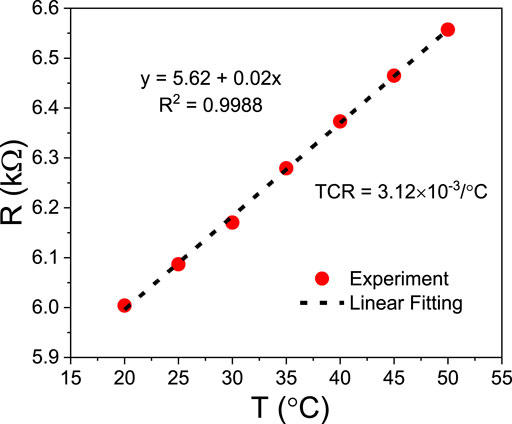
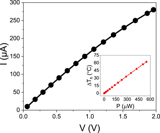
The resistance of the fabricated flow sensor was measured in an oven with an ambient temperature from 20 to 50°C. As shown in Figure 6, the measured TCR of the microheater is 3.12 × 10⁻³/°C, which is approximately equal to the commonly used material (platinum) for thermal flow sensors. The positive TCR means that the resistance of the microheater made of polysilicon is proportional to the temperature. Further, source current ranging from 10 to 280 μA was applied in the microheater to reveal the relationship between the resistance of the microheater and its power consumption. Figure 7 shows that only 462 μW of the power consumption is needed to increase the resistance of the microheater to 6.83 kΩ, where the overheated temperature of the NHF sensor is 53 K.
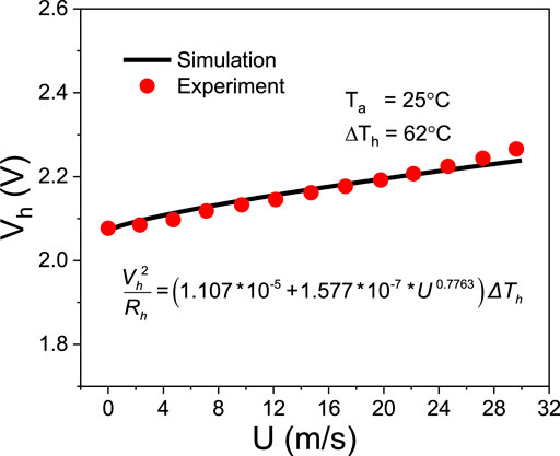
Figure 8 shows the steady output of the NHF sensor under CT mode, with the flow velocity ranging from 0 to 30 m/s. The parameters of A, B, n of the ECM are extracted from the measured results. It is demonstrated that the performance of the flow sensor predicted by the ECM is in good agreement with experimental results. On this basis, further prediction on the dynamic response of the NHF sensor could be started.
For the test of the sensor response time, a 1 kHz square wave is adopted. Both ECM analysis and experimental results show similar trends in the square wave testing, as shown in Figures 9A,B. At the rising and falling edges of the square wave, the sensor output under CT mode is disturbed first and then becomes stable again. The method to define the response time of the NHF sensor is exhibited in Figure 9B (Chen and Chang Liu, 2003). According to the measured data, the average response time of this sensor is 30 μs with the absence of the input flow. It is worth noting that this time constant τ will become smaller under high-speed flow, as the thermal resistance Rthermal will decrease due to the enhanced convective heat transfer.
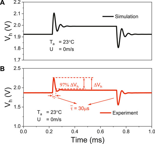
FIGURE 9. Square wave response of the NHF sensor under CT mode, including simulation results (A) and experiment results (B). The response time of NHF sensor with the absence of fluid flow is measured to be 30 µs.
For the frequency response test, the frequency of the adopted sine wave is changed from 50 Hz to 100 kHz. Figure 10 shows that the dynamical output of the NHF sensor first rises and then falls as the frequency of the sine wave increases. According to (Jiang et al., 1994), the cut-off frequency of the NHF sensor is identified as fc = 21 kHz in the absence of the input gas flow. The response of the sine wave testing verifies the time constant measurement in Figure 9, which corresponds to
where the parameter a falls into the most reported value between 1.3 and 1.6 (Freymuth, 1977; Li, 2004).
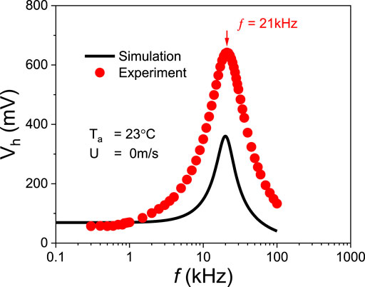
FIGURE 10. Sine wave response of the NHF sensor under CT mode, including simulation and experiment results. The measured cut-off frequency of the sensor is 21 kHz.
In addition, ECM also successfully revealed the frequency characteristics of the NHF sensor in CT mode. Therefore, this proposed ECM will be very useful for the design and optimization of high-performance hot-wire sensors.
Table 1 summarizes the proposed flow sensor’s performance and compares it with reported works. It can be seen that our flow sensor achieves better performance, including a wide detectable flow range, low power consumption, and short response time. Notably, Jiang’s work was implemented in pure MEMS technology (Jiang et al., 1994), which achieves a faster response time than that of this work, mainly due to its length (10 μm) being much smaller than that of our sensor. However, it is not difficult to reduce the NHF sensor length in CMOS-MEMS technology. While in this work, we have tackled the difficulty to narrow the wire width down to nano-scale, which is not achievable in most reported works, especially in CMOS-MEMS technology.
Conclusion
We developed a CMOS-MEMS based NHF sensor and investigated the sensor dynamic response under CT mode through square wave and sine wave tests. Since the width of the fabricated sensing wire is reduced to the nanometer scale, the NHF sensor achieves a wide detectable flow range of 0–30 m/s, a low power consumption of 500 μW, a short response time of 30 µs, and a wide bandwidth of 21 kHz. The ultrafast performance achieved by this NHF sensor will enable it for the turbulent flow measurement in aerodynamics. Moreover, an efficient ECM is proposed, which can well predict not only the steady-state response of the NHF sensor but also its dynamic response. Therefore, the proposed ECM will be a very useful tool to assist the design and optimization of high-performance hot-wire sensors in the future.
Data Availability Statement
The original contributions presented in the study are included in the article/Supplementary Material, further inquiries can be directed to the corresponding author.
Author Contributions
XW designed and fabricated the flow device. ZF conducted the experiment, analyzed the data, and wrote the manuscript. XS provided some figures and performed FEM simulation. WX offered ideas and revised the manuscript. All authors commented on the manuscript.
Funding
This research was partially supported by a grant from National Natural Science Foundation of China (52105582), Natural Science Foundation of Guangdong Province (2020A1515011555), high-Talent Research Funding (827-000451), Fundamental Research Foundation of Shenzhen (JCYJ20210324095210030), Open Foundation of The State Key Laboratory of Digital Manufacturing Equipment and Technology (DMETKF2021016), and Beijing Institute of Technology Research Fund Program for Young Scholars.
Conflict of Interest
The authors declare that the research was conducted in the absence of any commercial or financial relationships that could be construed as a potential conflict of interest.
Publisher’s Note
All claims expressed in this article are solely those of the authors and do not necessarily represent those of their affiliated organizations, or those of the publisher, the editors and the reviewers. Any product that may be evaluated in this article, or claim that may be made by its manufacturer, is not guaranteed or endorsed by the publisher.
Supplementary Material
The Supplementary Material for this article can be found online at: https://www.frontiersin.org/articles/10.3389/fmech.2022.877754/full#supplementary-material
References
Ashauer, M., Scholz, H., Briegel, R., Sandmaier, H., and Lang, W. (2001). “Thermal Flow Sensors for Very Small Flow Rate,” in Transducers’ 01 Eurosensors XV (Berlin, Heidelberg: Springer), 1436–1439. doi:10.1007/978-3-642-59497-7_339
Bailey, S. C. C., Kunkel, G. J., Hultmark, M., Vallikivi, M., Hill, J. P., Meyer, K. A., et al. (2010). Turbulence Measurements Using a Nanoscale thermal Anemometry Probe. J. Fluid Mech. 663, 160–179. doi:10.1017/s0022112010003447
Balakrishnan, V., Dinh, T., Phan, H.-P., Dao, D. V., and Nguyen, N.-T. (2018). Highly Sensitive 3C-SiC on Glass Based Thermal Flow Sensor Realized Using MEMS Technology. Sensors Actuators A: Phys. 279, 293–305. doi:10.1016/j.sna.2018.06.025
Berthet, H., Jundt, J., Durivault, J., Mercier, B., and Angelescu, D. (2011). Time-of-Flight Thermal Flowrate Sensor for Lab-On-Chip Applications. Lab. Chip 11 (2), 215–223. doi:10.1039/c0lc00229a
Borky, J., and Wise, K. (1979). Integrated Signal Conditioning for Diaphragm Pressure Sensors IEEE International Solid-State Circuits Conference. Digest of Technical Papers. IEEE 22, 196–197. doi:10.1109/isscc.1979.1155903
Bruun, H. H., Khan, M. A., Al-Kayiem, H. H., and Fardad, A. A. (1988). Velocity Calibration Relationships for Hot-Wire Anemometry. J. Phys. E: Sci. Instrum. 21 (2), 225–232. doi:10.1088/0022-3735/21/2/020
Buchner, R., Sosna, C., Maiwald, M., Benecke, W., and Lang, W. (2006). A High-Temperature Thermopile Fabrication Process for Thermal Flow Sensors. Sensors Actuators A: Phys. 130-131, 262–266. doi:10.1016/j.sna.2006.02.009
Byon, C. (2015). Numerical and Analytic Study on the Time-Of-Flight Thermal Flow Sensor. Int. J. Heat Mass Transfer 89, 454–459. doi:10.1016/j.ijheatmasstransfer.2015.05.011
Chen, J., and Chang Liu, C. (2003). Development and Characterization of Surface Micromachined, Out-Of-Plane Hot-Wire Anemometer. J. Microelectromech. Syst. 12 (6), 979–988. doi:10.1109/jmems.2003.820261
Comte-Bellot, G. (1976). Hot-Wire Anemometry. Annu. Rev. Fluid Mech. 8 (1), 209–231. doi:10.1146/annurev.fl.08.010176.001233
De Luca, A., and Udrea, F. (2017). CMOS MEMS Hot-Film Thermoelectronic Flow Sensor. IEEE Sens. Lett. 1 (6), 1–4. doi:10.1109/lsens.2017.2757086
Elwenspoek, M. (1999). “Thermal Flow Micro Sensors,” in CAS '99 Proceedings. 1999 International Semiconductor Conference (Cat. No.99TH8389), Akita, Oct. 1999 (IEEE), 423–435.
Feynman, R. P. (1992). There's Plenty of Room at the Bottom [Data Storage]. J. Microelectromech. Syst. 1 (1), 60–66. doi:10.1109/84.128057
Fisk, W. J., and De Almeida, A. T. (1998). Sensor-Based Demand-Controlled Ventilation: A Review. Energy and Buildings 29, 35–45. doi:10.1016/s0378-7788(98)00029-2
Freymuth, P. (1977). Frequency Response and Electronic Testing for Constant-Temperature Hot-Wire Anemometers. J. Phys. E: Sci. Instrum. 10 (7), 705–710. doi:10.1088/0022-3735/10/7/012
Gray, M., Meehan, J., Ward, C., Langdon, S. P., Kunkler, I. H., Murray, A., et al. (2018). Implantable Biosensors and Their Contribution to the Future of Precision Medicine. Vet. J. 239, 21–29. doi:10.1016/j.tvjl.2018.07.011
Heyd, R., Hadaoui, A., Fliyou, M., Koumina, A., Ameziane, L. E. H., Outzourhit, A., et al. (2010). Development of Absolute Hot-Wire Anemometry by the 3ω Method. Rev. Scientific Instr. 81 (4), 044901. doi:10.1063/1.3374015
Jiang, F., Tai, Y. C., Ho, C. M., Karan, R., and Garstenauer, M. (1994). “Theoretical and Experimental Studies of Micromachined Hot-Wire Anemometers,” in Proceedings of 1994 IEEE International Electron Devices Meeting, San Francisco, Dec. 1994 (IEEE), 139–142.
King, L. V. (1914). On the Convection of Heat from Small Cylinders in a Stream of Fluid: Determination of the Convection Constants of Small Platinum Wires, with Applications to Hot-Wire Anemometry. Proc. R. Soc. London. Series A 90, 563–570. doi:10.1098/rspa.1914.0089
Kitsos, V., Demosthenous, A., and Liu, X. (2019). A Smart Dual-Mode Calorimetric Flow Sensor. IEEE Sensors J. 20 (3), 1499–1508. doi:10.1109/jsen.2019.2946759
Kohl, F., Fasching, R., Keplinger, F., Chabicovsky, R., Jachimowicz, A., and Urban, G. (2003). Development of Miniaturized Semiconductor Flow Sensors. Measurement 33 (2), 109–119. doi:10.1016/s0263-2241(02)00058-1
Kohl, F., Beigelbeck, R., Cerimovic, S., Talic, A., Schalko, J., and Jachimowicz, A. (2007). “Comparison of the Dynamic Response of Calorimetric and Hot-Film Flow Transducers,” in Proceedings of 6th IEEE Sensors Conference, Atlanta, Oct. 2007 (IEEE), 341–344. doi:10.1109/icsens.2007.4388405
Kuehnel, W., and Sherman, S. (1994). A Surface Micromachined Silicon Accelerometer with On-Chip Detection Circuitry. Sensors Actuators A: Phys. 45 (1), 7–16. doi:10.1016/0924-4247(94)00815-9
Kunkel, G., Arnold, C., and Smits, A. (2006). “Development of NSTAP: Nanoscale thermal Anemometry Probe,” in Proceedings of the 36th AIAA Fluid Dynamics Conference and Exhibit, San Francisco, California, Jun 2012, 3718. doi:10.2514/6.2006-3718
Kuo, J. T. W., Yu, L., and Meng, E. (2012). Micromachined Thermal Flow Sensors-A Review. Micromachines 3 (3), 550–573. doi:10.3390/mi3030550
Li, J. D. (2004). Dynamic Response of Constant Temperature Hot-Wire System in Turbulence Velocity Measurements. Meas. Sci. Technol. 15 (9), 1835–1847. doi:10.1088/0957-0233/15/9/022
Mailly, F., Giani, A., Bonnot, R., Temple-Boyer, P., Pascal-Delannoy, F., Foucaran, A., et al. (2001). Anemometer with Hot Platinum Thin Film. Sensors Actuators A: Phys. 94 (1-2), 32–38. doi:10.1016/s0924-4247(01)00668-9
Mehmood, Z., Haneef, I., Ali, S. Z., and Udrea, F. (2019). Sensitivity Enhancement of Silicon-On-Insulator CMOS MEMS Thermal Hot-Film Flow Sensors by Minimizing Membrane Conductive Heat Losses. Sensors 19 (8), 1860. doi:10.3390/s19081860
Miao, Z., Chao, C. Y. H., Chiu, Y., Lin, C. W., and Lee, Y. K. (2014). “Design and Fabrication of Micro Hot-Wire Flow Sensor Using 0.35 μm CMOS MEMS Technology,” in Proceedings of the 9th IEEE International Conference on Nano/Micro Engineered and Molecular Systems (NEMS), Waikiki Beach, April 2014 (IEEE), 289–293.
Nguyen, N. T. (1997). Micromachined Flow Sensors-A Review. Flow Meas. Instrumentation 8 (1), 7–16. doi:10.1016/s0955-5986(97)00019-8
Qiu, L., Hein, S., Obermeier, E., and Schubert, A. (1996). Micro Gas-Flow Sensor with Integrated Heat Sink and Flow Guide. Sensors Actuators A: Phys. 54 (1-3), 547–551. doi:10.1016/s0924-4247(97)80012-x
Qu, H. (2016). CMOS MEMS Fabrication Technologies and Devices. Micromachines 7 (1), 14. doi:10.3390/mi7010014
Shikida, M., Naito, J., Yokota, T., Kawabe, T., Hayashi, Y., and Sato, K. (2009). A Catheter-Type Flow Sensor for Measurement of Aspirated- and Inspired-Air Characteristics in the Bronchial Region. J. Micromech. Microeng. 19 (10), 105027. doi:10.1088/0960-1317/19/10/105027
Sosna, C., Walter, T., and Lang, W. (2011). Response Time of Thermal Flow Sensors with Air as Fluid. Sensors Actuators A: Phys. 172 (1), 15–20. doi:10.1016/j.sna.2011.02.023
Tai, Y.-C., and Muller, R. S. (1988). Lightly-Doped Polysilicon Bridge as a Flow Meter. Sensors and Actuators 15 (1), 63–75. doi:10.1016/0250-6874(88)85018-2
Verhoeven, H. J., and Huijsing, J. H. (1996). Design of Integrated Thermal Flow Sensors Using Thermal Sigma—Delta Modulation. Sensors Actuators A: Phys. 52 (1-3), 198–202. doi:10.1016/0924-4247(96)80149-x
Wang, Y.-H., Chen, C.-P., Chang, C.-M., Lin, C.-P., Lin, C.-H., Fu, L.-M., et al. (2009). MEMS-Based Gas Flow Sensors. Microfluid Nanofluid 6, 333–346. doi:10.1007/s10404-008-0383-4
Xu, W., Wang, X., Wang, R., Xu, J., and Lee, Y. K. (2020). CMOS MEMS Thermal Flow Sensor with Enhanced Sensitivity for Heating, Ventilation, and Air Conditioning Application[J]. IEEE Trans. Ind. Elect. 68 (5), 4468–4476. doi:10.1109/tie.2020.2984446
Xu, W., Wang, X., Ke, Z., and Lee, Y.-K. (2022). Bidirectional CMOS-MEMS Airflow Sensor with Sub-mW Power Consumption and High Sensitivity. IEEE Trans. Ind. Electron. 69 (3), 3183–3192. doi:10.1109/tie.2021.3066945
Keywords: COMS-MEMS, nanoscale, hot-wire, response time, cut-off frequency
Citation: Wang X, Fang Z, Song X and Xu W (2022) A Nanoscale Hot-Wire Flow Sensor Based on CMOS-MEMS Technology. Front. Mech. Eng 8:877754. doi: 10.3389/fmech.2022.877754
Received: 17 February 2022; Accepted: 28 March 2022;
Published: 27 April 2022.
Edited by:
Sheng-Shian Li, National Tsing Hua University, TaiwanReviewed by:
Wan-Chun Chuang, National Sun Yat-sen University, TaiwanChing-Liang Dai, National Chung Hsing University, Taiwan
Copyright © 2022 Wang, Fang, Song and Xu. This is an open-access article distributed under the terms of the Creative Commons Attribution License (CC BY). The use, distribution or reproduction in other forums is permitted, provided the original author(s) and the copyright owner(s) are credited and that the original publication in this journal is cited, in accordance with accepted academic practice. No use, distribution or reproduction is permitted which does not comply with these terms.
*Correspondence: Wei Xu, weixu@szu.edu.cn
†These authors have contributed equally to this work
 Xiaoyi Wang
