 Winner Anigbogu
 Hieu Nguyen
 Hamzeh Bardaweel
- 1Institute for Micromanufacturing, College of Engineering and Science, Louisiana Tech University, Ruston, LA, United States
- 2Department of Mechanical Engineering, College of Engineering and Science, Louisiana Tech University, Ruston, LA, United States
- 3Department of Nanosystems Engineering, College of Engineering and Science, Louisiana Tech University, Ruston, LA, United States
Layered metamaterial beam structures are gaining attention in a variety of fields including vibration attenuation and energy harvesting. Exhaustive research on single-beam metamaterial vibration attenuation structures using local resonators exists in literature. Moreover, there are recent attempts at modelling double-layered beams with different kinds of constraints. The double-layered beam models in literature are limited to simple beams and not extended to metamaterials with local resonators. This article is focused on developing a design criterion and a modelling platform for layered metamaterial structures with multiple beams and local resonators for vibration isolation. The model is developed using Euler-Bernoulli beam equations, superposition of mode shapes and Galerkin methods. A prototype layered metamaterial structure is fabricated and characterized experimentally. The prototype consists of horizontal beams, local resonators forming unit cells, and vertical beams linkages. Each local resonator consists of cantilevers with tip masses. Results show good agreement between model and experiment. Two major bandgaps are observed at 190–410 Hz and 550–710 Hz. Results reveal that the low frequency bandgap can be further reduced through the design of the local resonators. Results also show that alternating the length of the local resonators causes a shift in the first frequency bandgap. An increase in the number of local resonators opens up extra frequency bandgaps at lower frequencies with the drawback of reducing the depth in vibration transmissibility. Moreover, the higher frequency bandgaps are mostly affected by the horizontal beams. An increase in the length of the horizontal beams, while the number and design of the local resonators are fixed, broadens the second frequency bandgap and shifts it to lower values.
1 Introduction
Recently, mechanical metamaterials have become the centerpiece of many research studies and engineering applications (Xia et al., 2020). This is mainly because of their unique properties including the presence of frequency bandgaps influenced by the local resonators (Wang et al., 2016; Jiang, He, 2017). This is particularly of interest for many engineering applications including wave guiding, vibration attenuation and, more recently, dual-purpose vibration suppression and energy scavenging (Matlack et al., 2016; Reichl and Inman, 2017; Casablanca et al., 2018). Frequency bandgaps created in these metamaterial structures originate from the ability of the local resonators to absorb kinetic energy from the oscillations passing through the metamaterial structure (Li et al., 2017). When the frequency of the external vibration source aligns with the resonant frequency of the local resonators, energy from these oscillations is transferred to the local resonators (Krödel et al., 2015; Li et al., 2017). Typically, these local resonators are either attached to the surface of the metamaterial structures or embedded inside (Fang et al., 2006; Chen and Wang, 2014; Krödel et al., 2015). Moreover, the Bragg’s scattering in the periodic structures leads to generation of frequency bandgaps (Kushwaha et al., 1993). The bandgaps generated by Bragg’s scattering are influenced by the wavelengths of the Bragg scattering mechanism, which is limited by the design of the beam of the mechanical metamaterial structure (Krödel et al., 2015). The addition of local resonators to the structure makes it possible to generate bandgaps at frequencies much lower than the Bragg’s frequencies (Liu et al., 2000; Liu et al., 2005). In the case of vibration attenuation, when the mechanical metamaterial is subject to vibrations by an external vibration source, it has the ability to suppress these oscillations, at low frequencies, that are closely aligned with the resonant frequency of the local resonators (Sugino et al., 2017).
Exhaustive literature has already looked at design criteria and characterization of metamaterial structures that are made of single beam structures with local resonators (Yu et al., 2006a; Yu et al., 2006b; Wang et al., 2013; Wang and Wang, 2013; Xiao et al., 2013; Zhou et al., 2017). For example, the work by Liu et al. was among the first few studies to look at metamaterial structures and local resonators (Liu et al., 2000). Their pioneer seminal work showed that localized resonant structures exhibit valuable characteristics such as negative elastic constants, leading to generation of low frequency bandgaps. The transfer matrix method was then used by Yu et al. for characterization of a single beam metamaterial structure with resonators that are made of rubber and copper rings (Yu et al., 2006a; Yu et al., 2006b). The results from their model simulations were validated experimentally. Xiao et al. built on the analytical model of the single beam metamaterial design developed by Yu et al. and showed that resonance and Bragg’s bandgaps exist as a result of local resonance effect and periodicity of unit cells (Xiao et al., 2013). Further studied the effects of different design parameters on the generated frequency bandgaps Liu et al. (2007). The results from their work revealed that, although a large local resonator generates wide attenuation, a large number of small local resonators spread across the beam gives enhanced attenuation spectra.
Other enhanced designs and studies of single beam-based metamaterial structures have also been developed (Chen et al., 2011; Xiao et al., 2012; Wang et al., 2013; Wang and Wang, 2013; Hu et al., 2021). For instance, a design of a beam with spring-mass local resonators sandwiched inside the beam was proposed by Chen et al. (2011). Results showed that the amplitude of waves was attenuated near the resonance frequency of the local resonators. Additionally, their results revealed that bandgaps were influenced mostly by the size of the internal mass rather than the spring constant of the resonator. To create more flexible bandgaps, designed an array of local resonators with varying resonant frequencies Xiao et al. (2012). Their work showed that, compared to a beam with a single array of local resonators, a beam with varying array of local resonators can generate broader bandgaps above and below Bragg’s bandgap. Used a combination of both vertical springs and oblique springs to investigate the effect of negative stiffness introduced by the oblique springs on single beam-based metamaterial structures Zhou et al. (2017). Their results showed that adding two oblique springs to the single beam-based metamaterial structure introduced negative stiffness which effectively produced attenuation at lower frequencies. More recently, studied the effect of nonlinearity that was purposefully introduced into the design of a single beam-based metamaterial structure Xia et al. (2020). This was done by adding bistable attachments to the metamaterial structure. Their work showed that nonlinear vibrations of the bistable resonator attachments resulted in wider frequency bandgap compared to the case when only linear local resonators were considered.
All the aforementioned studies have focused on single-beam based metamaterial structures with local resonators. On the other hand, few recent studies have looked at modelling layered beams. For example, Oniszczuk investigated two beams connected by a Winker elastic layer (Oniszczuk, 2000). The work used Bernoulli-Fourier method to show that the free vibration of a simply supported double-beam system is similar to a double-string system. Used both Fourier and Laplace approach to develop a closed form solution for double infinite Euler-Bernoulli beams with harmonic loads applied Li et al. (2019). Douglas et al. treated a system of three elastic-viscoelastic beams as two non-identical Euler-Bernoulli beams with a viscoelastic layer between them (Douglas and Yang, 1978). The method was limited to a specific fixed-free boundary condition and an external load applied only at the free end. Extended Euler-Bernoulli’s approach to arbitrary boundary conditions and applied loads Vu et al. (2000). Then applied a change of variable method in decoupling the set of fourth-order differential equations from the modal solution of double Euler-Bernoulli beams with moving loads Abu-Hilal (2006). Recently demonstrated the use of layered metamaterial for simultaneous vibration isolation and energy harvesting Li et al. (2017). Anigbogu et al. presented a unique metamaterial design using 3D printed layered beams to achieve vibration attenuation (Anigbogu and Bardaweel, 2020). Their results showed that layered metamaterial beams can achieve vibration attenuation at low frequencies that are commonly encountered in nature.
A key observation from these recent studies is that these efforts have mainly focused on studying and investigating either single beam-based metamaterial structures or double-beams with different support systems. None of these studies has tackled the issue of developing a general approach to modelling layered metamaterial beams with local resonators. The work presented in this article is motivated by the growing interest in layered metamaterial beams with local resonators. Recently, these layered metamaterial beams with local resonators have found numerous potential engineering applications including vibration attenuation and energy scavenging (Li et al., 2017; Anigbogu and Bardaweel, 2020). To the best knowledge of the authors, the work presented here is the first to tackle the issue of developing a modelling platform for layered metamaterial structures with multiple beams and local resonators. The work is focused on developing design criteria and modelling platform for layered metamaterial structures with multiple beams and local resonators. The model is developed using Galerkin method and superposition of mode shapes to solve an application of Euler-Bernoulli equation to layered-metamaterial beam structures. A prototype of the layered metamaterial structure with local resonators is fabricated and characterized experimentally. The model developed in this work is then validated against measured data. Additionally, in this work design criteria and the effects of core design parameters on the frequency bandgaps generated by the layered metamaterial structure are studied. Section 2 describes the theory and mathematical model developed for the layered metamaterial structure. Section 3 introduces the experimental methods, while Section 4 describes the main findings and discussions of these results. Conclusions and summary of the work are articulated in Section 5.
2 Theory and Model Development
The overall representation of the layered metamaterial vibration attenuation structure is shown in Figure 1A. The metamaterial structure is comprised of J-layered horizontal beams, the local resonators per unit cell and the vertical beams linking the horizontal beams together. The local resonators are made of cantilevers with tip masses attached to them as shown in Figure 1A. Each unit cell has four local resonators linked to the same point as shown in Figure 1B. For simplicity we represent the unit cell as one single local resonator force acting on the same point, in tandem with the approach adopted by Wang et al. in (Wang and Wang, 2013). The effects of the vertical beams are factored into the governing equations as spring forces and damping forces following the relative velocities of the beams as shown in Figure 2. The free body diagram of the local resonators within a unit cell is shown in Figure 3. An approximate model of the transmissibility of the layered metamaterial structure is obtained using Euler-Bernoulli’s equations and Galerkin method (Zhou et al., 2017).
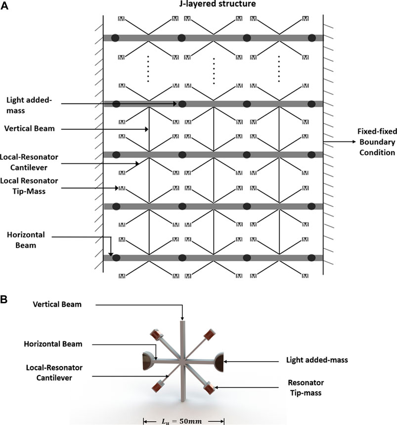
FIGURE 1. Schematic description of a j-layered metamaterial structure and its coupled parts: (A) Layered metamaterial structure constituents including horizontal beams, vertical beams and local resonators, and (B) Representation of the basic unit cell of the layered metamaterial assembly. It is comprised of local resonators with tip masses and vertical columns attached to the beam. The length of a unit cell is 50 mm.
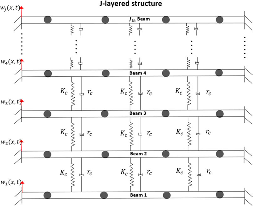
FIGURE 2. Schematic diagram of the free body diagram for the vertical beams attached to each unit cell and between the horizontal beams of a j-layered metamaterial structure.
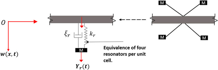
FIGURE 3. Free body diagram of a local resonator. The four local resonators acting at a point in the unit cell are reduced into an equivalent single local resonator unit cell in the model.
In order to analyze the dynamic behavior of the layered metamaterial vibration attenuation structure when subject to external vibrations, the Frequency Response Function (FRF) approach is used to determine the transmissibility of the device. The Galerkin method is used to analyze the beams’ response to external vibrations. The length of each horizontal beam is
where
In Eq. 2,
Next, we extend Eq. 1 to factor in the connecting vertical beams as shown in Figures 1, 2. This yields the set of equations representing each of the horizontal beams from the base beam to the top, respectively. A generalized form of this set of equations from the lowest horizontal beam, i.e.,
where
where
Grouping the impact of the vertical beams as forces acting at specific points on the horizontal beams, Eq. 3 can be rewritten in the following generalized forms:
where
Also, the forces from the attached local resonators and the internal damping force are given as:
where
Substituting Eq. 2 into Eq. 5 yields the following set of equations, respectively:
Multiplying Eq. 9 by the trial function
Here, the transverse displacements,
In Eq. 10 the impact of damping on the layered metamaterial structure is considered. Here,
Moreover, the wave number
Furthermore, using Newton’s second law, the movement of each
Solving Eqs 10, 14 simultaneously using Runge-Kutta numerical method, the generalized displacements and the local resonator displacement are obtained. The obtained resonator displacement is then substituted into Eq. 2, in order to obtain the displacement of the horizontal beam. This Galerkin solution is truncated at N = 4. Transmissibility is taken as the output displacement at the center of the most upper horizontal beam, i.e.
3 Experimental Methods
In this section experimental methods are described. Mainly, a brief description of fabrication and assembly of the layered metamaterial vibration attenuation structure as well as experimental setup used for characterization are discussed. Experimental work was focused on measuring the transmissibility of the layered metamaterial vibration attenuation structure. Model simulations were then validated against these experimental measurements.
The layered metamaterial structure was designed using Solidworks CAD software, then changed into an STL (STereoLithography) format that is suitable for 3D printing. PETG (polyethylene terephthalate) was used as the printing filament in the Ultimaker 3 Fused Deposition Modeling (3D FDM) printer. The local resonators (cantilever beams) were designed in a way that allowed insertion of additional masses at their tips. The tip-masses were created separately and then slotted into the tips of the local resonators. These additional tip-masses were vital in lowering the resonant frequencies of local resonators to less than 300 Hz. Figure 4 shows a prototype of the layered metamaterial vibration attenuation structure fabricated in this work. For this work, a layered metamaterial beam structure with four horizontal beams
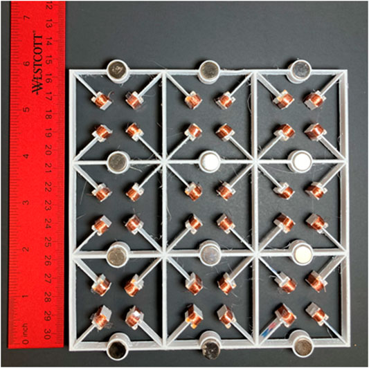
FIGURE 4. A 4 x 4 prototype of the manufactured layered metamaterial vibration attenuation structure presented and modeled in this work.
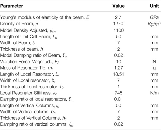
TABLE 1. Design parameters of the layered metamaterial structure.
The set-up of the experiment is shown in Figure 5. First, an external vibration waveform was generated by the controller (S81B–P02, SENTEK DYNAMICS). This waveform was then passed through the power amplifier (LA-800, SENTEK DYNAMICS) for amplification, before reaching the shaker table (VT-500, SENTEK DYNAMICS). The electromagnetic shaker table was used to apply the external vibration input to the layered metamaterial structure that was fixed on top of the shaker table. The shaker table was operated at predetermined frequency range of 50–700 Hz, and acceleration level of 0.5 g [m s−2]. The sides of the layered metamaterial vibration attenuation structure were held with a fixture and clamps. Two accelerometers (PCB333B30 model, PCB Piezotronics) were used to capture the input signal from the shaker table and the output signal from the top of the layered metamaterial structure. The first accelerometer was placed on top of the shaker table to capture the input signal data, while the second accelerometer was positioned on top of the layered metamaterial structure to capture the output signal. The input and output signals were both monitored using Crystal Instrument’s Engineering Data Management (EDM) software on a PC. The transmissibility was analyzed by comparing the output acceleration from the top-most beam of the metamaterial structure to the input acceleration from the vibration source, i.e., shaker table.
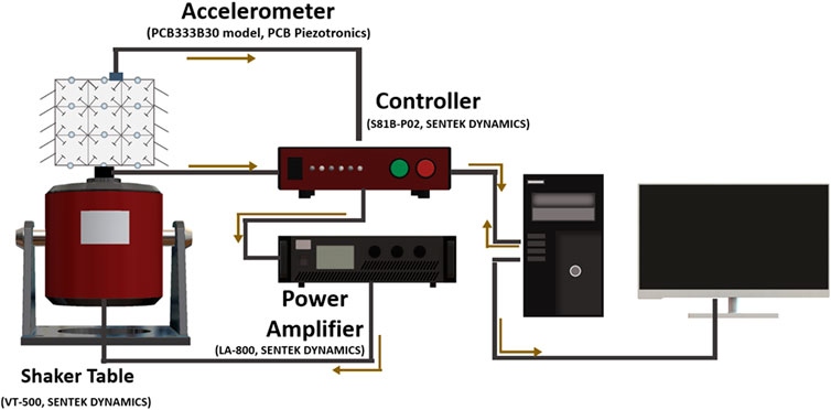
FIGURE 5. Cartoon schematic of the experimental set-up used for measuring the transmissibility of the layered metamaterial vibration attenuation structure presented in this work.
4 Results and Discussion
The results from the FRF analysis were obtained from Eq. 15 as the Root Mean Square ratio between the output displacement (at the center of the upper beam) and the input displacement (from the vibration source) (Zhou et al., 2017). The parameters used in this study are shown in Table 1. For the purpose of model validation and design investigation, a layered metamaterial structure made of 3 unit cells per beam, three vertical columns between beams, and a total of four horizontal beams was manufactured (Figure 4). In this study modes beyond the fourth modes were truncated because higher modes are unnecessary as have been shown in literature (Li et al., 2017). For example, the 5th mode of the unit cell is 1,469 Hz, which is much higher than the frequency range of interest in the current study (below 700 Hz). When frequencies much higher than 700 Hz are considered, the value of N should be increased to capture those higher modes (Zhou et al., 2017).
4.1 Model Simulation
First, we start by examining the displacement amplitude of the topmost local resonator, i.e., cantilever beam, and the lowest local resonator. Displacement response was obtained using Eq. 14 and results are shown in Figure 6. Results reveal peak displacement at approximately 220 Hz. This peak corresponds to the first fundamental resonant frequency of the unit cell which was also determined and verified using COMSOL simulations and found at, approximately, 224 Hz (Anigbogu and Bardaweel, 2020). The COMSOL simulation of the unit-cell was done using Bloch-Floquet’s periodic boundary condition. The unit-cell was modelled as a fine mesh comprised of 11,647 elements with a maximum size of 1.81 mm and a minimum size of 0.0775 mm (Anigbogu and Bardaweel, 2020).
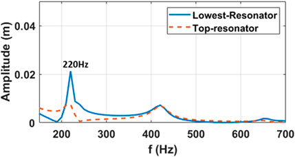
FIGURE 6. Displacement amplitude of local resonators at the top horizontal beam and the lowest horizontal beam showing resonant peak around 220 Hz, close to the overall resonant peak of the unit cell,
Next, the transmissibility of the metamaterial structure was estimated using Eq. 15 and the results are shown in Figure 7. Results reveal two main bandgaps of interests, i.e., below 700 Hz. Frequencies higher than 700 Hz were not considered in this work because most of mechanical vibrations in nature occur at frequencies well below the 700 Hz frequency limit adopted in this work (Li et al., 2017). The first bandgap expands from 190 to 410 Hz with its lowest transmissibility dip occurring at approximately 245 Hz. The second frequency bandgap takes place between 550 and 710 Hz with its lowest dip at approximately 600 Hz.
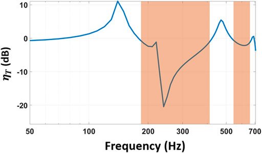
FIGURE 7. Transmissibility of the layered metamaterial vibration attenuation structure obtained using model simulations. The first bandgap (190–410 Hz) and the second bandgap (550–710 Hz) are shown in the shaded regions.
It is worth noting that the level of vibration attenuation, shown in Figure 7, observed within the first bandgap is significantly larger than the level of vibration attenuation observed in the second bandgap. This is likely because most of the vibrational energy is localized within the first bandgap. To further investigate this behavior, the input and output displacements of the layered metamaterial structure at frequency within the first bandgap,
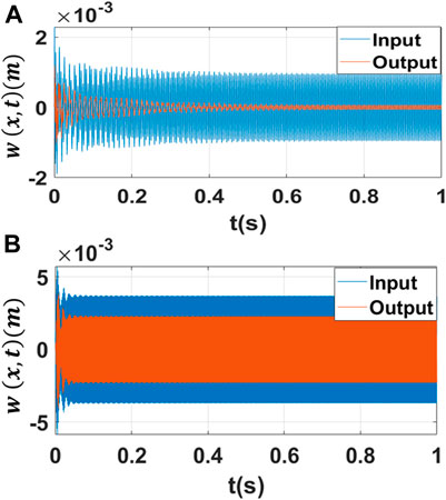
FIGURE 8. Model simulations of displacement response of the local resonators at the topmost beam and the lowest beam within the two main frequency bandgaps: (A) within the first bandgap at the unit cell’s resonant frequency,
4.2 Experimental Validation
Next, model simulations are validated against experimentally measured data and the results are shown in Figure 9. Measured data shown in Figure 9 were obtained using experiment setup shown in Figure 5. Results show a good agreement between model simulations (Figure 7) and measured data (Figure 9). While results from both model simulations and experimental data exhibit alike characteristics and trends some discrepancy is present. For example, model simulations predict a second bandgap of 550–710 Hz compared to the measured one, i.e., 587–639 Hz. This mismatch between model simulations and measured data may be attributed to a few factors. First, the mismatch between model simulations and experimental data may be attributed to the protrusions and cuts that exist in the fabricated layered metamaterial structure and were not factored into the model simulations. The presence of some extruded cuts and holes in the 3D printed layered metamaterial structure, coupled with defects accrued from assembling the tip masses and the 3D printed layered metamaterial structure may contribute to the slight mismatch between model and experiment. Second, printing parameters such as temperature, extrusion rate and speed may affect the quality of 3D printed structures (Mueller and Shea, 2000; Pilipović et al., 2009; Singh, 2011; Mueller et al., 2015; Li et al., 2017; Reichl et al., 2021). These are factors that cannot be readily accounted for in the developed model. For example, Reichl et al., found that changes in 3D printing temperature may affect the damping properties of cantilever vibration absorbers and therefore likely to adjust their resonant frequencies (Reichl et al., 2021). In this work, similar to the approach taken by Xia et al. fixed modal damping ratio was assumed for simplicity (Xia et al., 2020). Additionally, the slight mismatch between model simulations and experiment may be attributed to the experiment setup itself. For instance, deviation between dynamic model predictions and experiment was reported by Berdy et al. (2014), Lee et al. (2016), Dong et al. (2017), Dhote et al. (2018) and it was attributed to the likely presence of a small tilt in the experimental rig which may lead to multi-direction vibrations and damping that are not accounted for in the dynamic model.
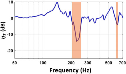
FIGURE 9. Measured transmissibility of the layered metamaterial vibration attenuation structure showing two notable frequency bandgaps, i.e., 205–257 Hz and 587–639 Hz.
4.3 Further Studies on the Dynamic Behavior of the Layered Metamaterial Structure
Next, design criteria and effects of different design parameters on the response of the layered metamaterial vibration attenuation structure are investigated using the developed model. Figure 10 shows the effect of the number of local resonators (unit cells) per beam on the transmissibility of the layered metamaterial structure. It is worth noting that each unit cell has a length,
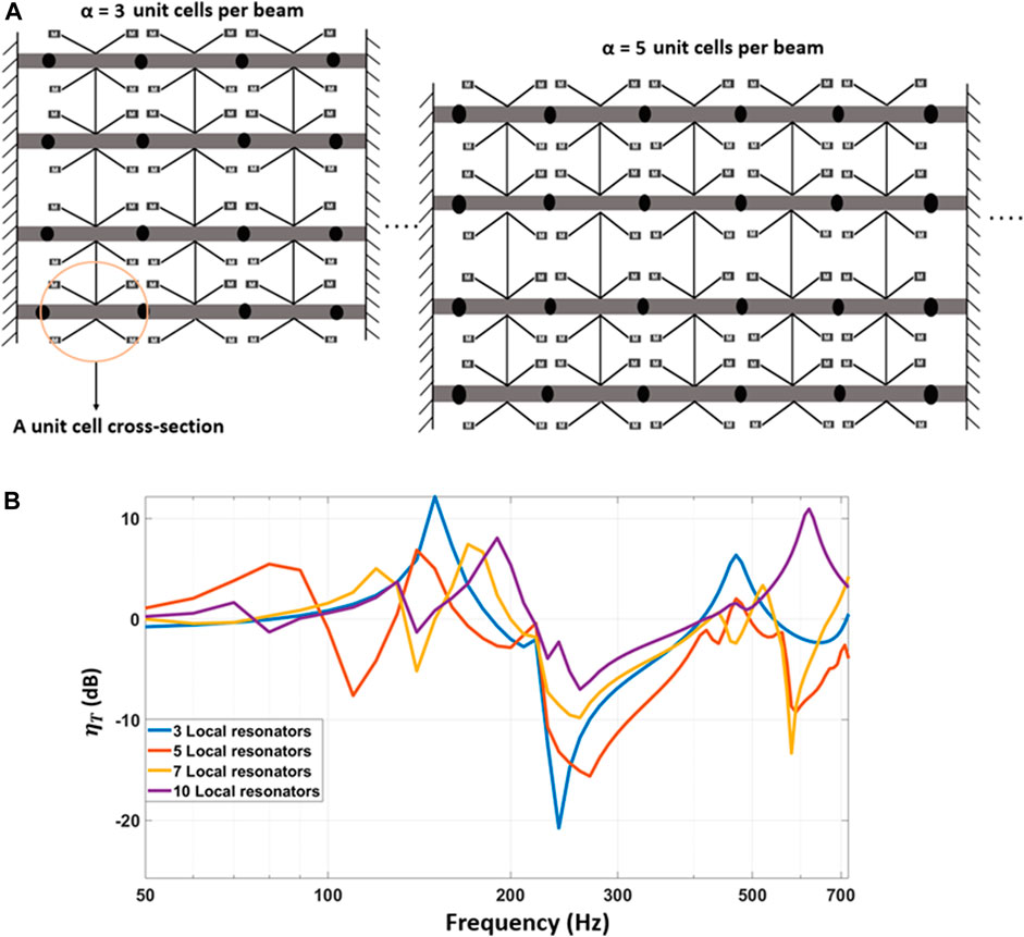
FIGURE 10. Effect of increasing the number of local resonators (unit cells) on the transmissibility behavior of the layered metamaterial vibration attenuation structure: (A) Graphical cartoon representation of changes in the layered metamaterial structure as the number of unit cells (local resonators) per beam increases from α = 3 to α = 5. (B) Model simulation of transmissibility when increasing the number of local resonators.
To further investigate the impact of the local resonators on the first frequency bandgap, the lengths of the resonators are varied and results are shown in Figure 11. Results show that increasing the length of the local resonators causes the first bandgap to move to lower frequencies. Results also suggest that when the length of the local resonators is increased above the nominal length,
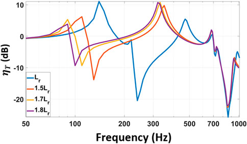
FIGURE 11. The effect of changing the length of the local resonators on vibration transmissibility of the layered metamaterial structure and the position of the first and second bandgaps.
Next, the impact of a change in the horizontal beams’ characteristics on the frequency bandgaps is further investigated. This is done through studying the effect of variations in the length of the unit cell beam,
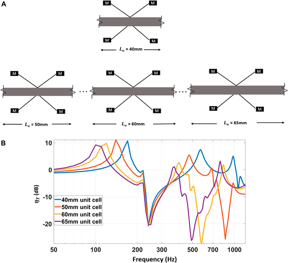
FIGURE 12. Transmissibility graphs showing the effects of changing the length of unit cells on the first and second bandgaps of the layered metamaterial structure: (A) Graphical cartoon representation of changes in the length of the unit cell of the layered metamaterial structure. Note: the number of unit cells per horizontal beam remains the same (α = 3), but the total length of the horizontal beam is changed as the length of the unit cell is varied, (B) the results of a change in length of unit cell, from 40 to 65 mm.
5 Conclusion
The focus of this article is studying layered metamaterial vibration attenuation structures with local resonators using both experimental methods and model simulations. In this work, design criteria and generalized modelling platform for layered metamaterial structures with local resonators have been established. A fundamental model has been developed using Galerkin method and superposition of modes to describe the dynamic response and transmissibility of the layered metamaterial vibration attenuation structure in response to an external vibration. The transverse vibrations of the layered metamaterial beams were represented with Euler-Bernoulli equation of beams. A prototype of the layered metamaterial structure has been fabricated and characterized experimentally. The prototyped layered metamaterial vibration attenuation structure constituents included four horizontal beams, local resonators forming unit cells, and vertical beams linking the horizontal beams together. Each local resonator consisted of cantilevers with tip masses, while horizontal beams were connected to each other via the vertical beams. Results show good agreement between model simulations and experimental data. Results also reveal the roadmap for successful design of layered metamaterial structures. For example, effects of various core design parameters in the layered metamaterial structure on the first and second frequency bandgaps have been investigated in this work. Main conclusions from these studies include:
• Altering the length of the local resonators primarily affects the shape and position of the local resonator frequency bandgap.
• An increase in the number of local resonators tends to open up extra frequency bandgaps at lower frequencies with the drawback of reducing the depth in vibration transmissibility.
• Another essential factor in shaping the transmissibility curves of these layered metamaterial structures is the horizontal beams hosting the local resonators. Direct changes to the horizontal beams tend to, mainly, affect the higher frequency bandgaps. An increase in the length of the horizontal beams, while the number and design of the local resonators are fixed, noticeably broadens the second frequency bandgap and shifts it to lower frequencies.
• Since most mechanical vibrations occur at low frequencies, i.e., less than 300 Hz, adjusting the design of local resonators within the layered metamaterial structures is more likely to yield desired lower frequency bandgaps.
Data Availability Statement
The original contributions presented in the study are included in the article/supplementary material, further inquiries can be directed to the corresponding author.
Author Contributions
WA was involved in the data collection, formal analysis, software, validation, investigation and visualization. HN was involved in formal analysis, software, and visualization. HB was responsible for the conceptualization, funding acquisition, methodology, project administration, resources, software supervision, validation, visualization, and writing, reviewing, and editing of the original draft.
Funding
This work was partially supported by the Louisiana Department of Transportation-Transportation Research Center (Contract DOTLT1000369) and Louisiana Board of Regents-LASPACE NASA program, Agreement Number (80NSSC20M0110). The views expressed in this article are those of the authors and do not reflect the official policy or position of the funding agencies.
Conflict of Interest
The authors declare that the research was conducted in the absence of any commercial or financial relationships that could be construed as a potential conflict of interest.
Publisher’s Note
All claims expressed in this article are solely those of the authors and do not necessarily represent those of their affiliated organizations, or those of the publisher, the editors and the reviewers. Any product that may be evaluated in this article, or claim that may be made by its manufacturer, is not guaranteed or endorsed by the publisher.
References
Abu-Hilal, M. "Dynamic Response of a Double Euler–Bernoulli Beam Due to a Moving Constant Load." J. Sound Vibration Vol. 297 No. 3 (2006): ppp. 477–491. doi:10.1016/j.jsv.2006.03.050
Anigbogu, W., and Bardaweel, H. (2020). A Metamaterial-Inspired Structure for Simultaneous Vibration Attenuation and Energy Harvesting. Shock and Vibration 2020, 4063025. doi:10.1155/2020/4063025
Berdy, D. F., Valentino, D. J., and Peroulis, D. "Design and Optimization of a Magnetically Sprung Block Magnet Vibration Energy Harvester." Sensors Actuators A: Phys. Vol. 218 (2014): ppp. 69–79. doi:10.1016/j.sna.2014.06.011
Casablanca, O., Ventura, G., Garescì, F., Azzerboni, B., Chiaia, B., Chiappini, M., et al. (2018). Seismic Isolation of Buildings Using Composite Foundations Based on Metamaterials. J. Appl. Phys. 123 (No. 17), 174903. doi:10.1063/1.5018005
Chen, J. S., Sharma, B., and Sun, C. T. "Dynamic Behaviour of Sandwich Structure Containing Spring-Mass Resonators." Compos. Structures Vol. 93 No. 8 (2011): ppp. 2120, 2125. doi:10.1016/j.compstruct.2011.02.007
Chen, Y., and Wang, L. (2014). Periodic Co-continuous Acoustic Metamaterials with Overlapping Locally Resonant and Bragg Band Gaps. Appl. Phys. Lett. 105 (No.19), 191907. doi:10.1063/1.4902129
Dhote, S., Yang, Z., Behdinan, K., and Zu, J. "Enhanced Broadband Multi-Mode Compliant Orthoplanar Spring Piezoelectric Vibration Energy Harvester Using Magnetic Force." Int. J. Mech. Sci. Vol. 135 (2018): ppp. 63–71. doi:10.1016/j.ijmecsci.2017.11.012
Dong, G., Zhang, X., Xie, S., Yan, B., and Luo, Y. "Simulated and Experimental Studies on a High-Static-Low-Dynamic Stiffness Isolator Using Magnetic Negative Stiffness Spring." Mech. Syst. Signal Process. Vol. 86 (2017): ppp. 188, 203. doi:10.1016/j.ymssp.2016.09.040
Douglas, B. E., and Yang, J. C. S. "Transverse Compressional Damping in the Vibratory Response of Elastic-Viscoelastic-Elastic Beams." AIAA J. Vol. 16 No. 9 (1978): ppp. 925–930. doi:10.2514/3.7595
Fang, N., Xi, D., Xu, J., Ambati, M., Srituravanich, W., Sun, C., et al. "Ultrasonic Metamaterials with Negative Modulus." Nat. Mater Vol. 5 No. 6 (2006): ppp. 452–456. doi:10.1038/nmat1644
Hu, G., C. M. Austin, A., Sorokin, V., and Tang, L. (2021). Metamaterial Beam with Graded Local Resonators for Broadband Vibration Suppression. Mech. Syst. Signal Process. 146, 106982. doi:10.1016/j.ymssp.2020.106982
Jiang, T., and He, Q. (2017). Dual-Directionally Tunable Metamaterial for Low-Frequency Vibration Isolation. Appl. Phys. Lett. 110 (No.2), 21907. doi:10.1063/1.4974034
Krödel, S., Thomé, N., and Daraio, C. "Wide Band-Gap Seismic Metastructures." Extreme Mech. Lett. Vol. 4 (2015): ppp. 111–117. doi:10.1016/j.eml.2015.05.004
Kushwaha, M. S., Halevi, P., Dobrzynski, L., and Djafari-Rouhani, B. (1993). Acoustic Band Structure of Periodic Elastic Composites. Phys. Rev. Lett. 71 (13), 2022–2025. doi:10.1103/physrevlett.71.2022
Lee, C., Stamp, D., Kapania, N. R., Mur-Miranda, , and Oscar, J. (2016). “Harvesting Vibration Energy Using Nonlinear Oscillations of an Electromagnetic Inductor,” in Proceedings of SPIE-The International Society for Optical Engineering. doi:10.1117/12.849895
Li, Y., Baker, E., Reissman, T., Sun, C., and Liu, W. K. (2017). Design of Mechanical Metamaterials for Simultaneous Vibration Isolation and Energy Harvesting. Appl. Phys. Lett. 111 (25), 251903. doi:10.1063/1.5008674
Li, B., Cheng, Y., Zhu, Z., and Zhang, F. "A Closed-form Solution for a Double Infinite Euler-Bernoulli Beam on a Viscoelastic Foundation Subjected to Harmonic Line Load." Earthq. Eng. Eng. Vib. Vol. 18 No. 1 (2019): ppp. 129, 140. doi:10.1007/s11803-019-0494-9
Liu, Z., Zhang, X., Mao, Y., Zhu, Y. Y., Yang, Z., Chan, C. T., et al. (2000).Locally Resonant Sonic Materials. Science, 289. 1734–1736. doi:10.1126/science.289.5485.1734
Liu, Y., Yu, D., Li, Li., Zhao, H., Wen, J., and Wen, X. (2007). Design Guidelines for Flexural Wave Attenuation of Slender Beams with Local Resonators. Phys. Lett. A 362 (5), 344–347. doi:10.1016/j.physleta.2006.10.056
Liu, Z., Chan, C. T., and Sheng, P. (2005). Analytic Model of Phononic Crystals with Local Resonances. Phys. Rev. B 71 (No.1), 14103. doi:10.1103/physrevb.71.014103
Matlack, K. H., Bauhofer, A., Krödel, S., Palermo, A., and Daraio, C. "Composite 3D-Printed Metastructures for Low-Frequency and Broadband Vibration Absorption." Proc. Natl. Acad. Sci. USA Vol. 113 No. 30 (2016): ppp. 8386, 8390. doi:10.1073/pnas.1600171113
Mueller, J., Kim, S. E., Shea, K., and Daraio, C. (2015). Tensile Properties of Inkjet 3D Printed Parts: Critical Process Parameters and Their Efficient Analysis. ASME Computers and Information in Engineering. doi:10.1115/DETC2015-48024
Mueller, J., and Shea, K. (2000). “The Effect of Build Orientation on the Mechanical Properties in Inkjet 3D-Printing,” in Proceedings of the 26th Annual International Solid Freeform Fabrication (SFF) Symposium, Austin, TX.
Oniszczuk, Z. "Free Transverse Vibrations Of Elastically Connected Simply Supported Double-Beam Complex System." J. Sound Vibration Vol. 232 No. 2 (2000): ppp. 387–403. doi:10.1006/jsvi.1999.2744
Pilipović, A., Raos, P., and Šercer, M. (2009). Experimental Analysis of Properties of Materials for Rapid Prototyping. Int. J. Adv. Manufacturing Tech. 40, 105.
Reichl, K. K., Avci, O., and Inman, D. J. "Temperature Dependent Damping in Additively Manufactured Polymer Structures." J. Appl. Comput. Mech. Vol. 7(2021): ppp. 993–1008.
Reichl, K. K., and Inman, D. J. "Lumped Mass Model of a 1D Metastructure for Vibration Suppression with No Additional Mass." J. Sound Vibration Vol. 403 (2017): ppp. 75–89. doi:10.1016/j.jsv.2017.05.026
Sharma, T., and Tyagi, A. "Review of Mechanical Modelling of Fixed-Fixed Beams in RF MEMS Switches.", 2013 Third International Conference on Advanced Computing and Communication Technologies (ACCT), ppp. 211–214. doi:10.1109/acct.2013.53
Singh, R. (2011). Process Capability Study of Polyjet Printing for Plastic Components. J. Mech. Sci. Technol. 25 (No. 4), 1011–1015. doi:10.1007/s12206-011-0203-8
Sugino, C., Xia, Y., Leadenham, S., Ruzzene, M., and Erturk, A. "A General Theory for Bandgap Estimation in Locally Resonant Metastructures." J. Sound Vibration Vol. 406 (2017): ppp. 104, 123. doi:10.1016/j.jsv.2017.06.004
Vu, H. V., Ordóñez, A. M., and Karnopp, B. H. "Vibration Of A Double-Beam System." J. Sound Vibration Vol. 229 No. 4 (2000): ppp. 807, 822. doi:10.1006/jsvi.1999.2528
Waichi, W., Azid, A., and Majlis, B. "Formulation of Stiffness Constant and Effective Mass for a Folded Beam." Arch. Mech. Vol. 62 (2010): ppp. 405–418.
Wang, M. Y., and Wang, X. (2013). Frequency Band Structure of Locally Resonant Periodic Flexural Beams Suspended with Force-Moment Resonators. J. Phys. D: Appl. Phys. 46 (No. 25), 255502. doi:10.1088/0022-3727/46/25/255502
Wang, Z., Zhang, P., and Zhang, Y. (2013). Locally Resonant Band Gaps in Flexural Vibrations of a Timoshenko Beam with Periodically Attached Multioscillators. Math. Probl. Eng. 2013, 146975. doi:10.1155/2013/146975
Wang, Z., Zhang, Q., Zhang, K., and Hu, G. "Tunable Digital Metamaterial for Broadband Vibration Isolation at Low Frequency." Adv. Mater. Vol. 28 No. 44 (2016): ppp. 9857, 9861. doi:10.1002/adma.201604009
Xia, Y., Ruzzene, M., and Erturk, A. "Bistable Attachments for Wideband Nonlinear Vibration Attenuation in a Metamaterial Beam." Nonlinear Dyn. Vol. 102 No. 3 (2020): ppp. 1285, 1296. doi:10.1007/s11071-020-06008-4
Xiao, Y., Wen, J., and Wen, X. "Broadband Locally Resonant Beams Containing Multiple Periodic Arrays of Attached Resonators." Phys. Lett. A Vol. 376 No. 16 (2012): ppp. 1384, 1390. doi:10.1016/j.physleta.2012.02.059
Xiao, Y., Wen, J., Yu, D., and Wen, X. "Flexural Wave Propagation in Beams with Periodically Attached Vibration Absorbers: Band-Gap Behavior and Band Formation Mechanisms." J. Sound Vibration Vol. 332 No. 4 (2013): ppp. 867–893. doi:10.1016/j.jsv.2012.09.035
Yu, D., Liu, Y., Wang, G., Zhao, H., and Qiu, J. (2006). Flexural Vibration Band Gaps in Timoshenko Beams with Locally Resonant Structures. J. Appl. Phys. 100 (No. 12), 124901. doi:10.1063/1.2400803
Yu, D., Liu, Y., Zhao, H., Wang, G., and Qiu, J. (2006). Flexural Vibration Band Gaps in Euler-Bernoulli Beams with Locally Resonant Structures with Two Degrees of Freedom. Phys. Rev. B 73 (No. 6), 64301. doi:10.1103/physrevb.73.064301
Keywords: layered metamaterial 1, local resonators 2, frequency bandgaps 3, mechanical metamaterial 4, 3D printing 5, metamaterial for vibration isolation 6
Citation: Anigbogu W, Nguyen H and Bardaweel H (2021) Layered Metamaterial Beam Structures With Local Resonators for Vibration Attenuation: Model and Experiment. Front. Mech. Eng 7:768508. doi: 10.3389/fmech.2021.768508
Received: 31 August 2021; Accepted: 05 October 2021;
Published: 25 October 2021.
Edited by:
Jaehyung Ju, Shanghai Jiao Tong University, ChinaReviewed by:
Giorgio Carta, University of Cagliari, ItalyKaveh Rajabi, Iran University of Science and Technology, Iran
Hu Liu, Nanyang Technological University, Singapore
Copyright © 2021 Anigbogu, Nguyen and Bardaweel. This is an open-access article distributed under the terms of the Creative Commons Attribution License (CC BY). The use, distribution or reproduction in other forums is permitted, provided the original author(s) and the copyright owner(s) are credited and that the original publication in this journal is cited, in accordance with accepted academic practice. No use, distribution or reproduction is permitted which does not comply with these terms.
*Correspondence: Hamzeh Bardaweel, SGFtemVoQkBsYXRlY2guZWR1