 Yang Xu
 Rongxin Zhou
- 1School of Mechanical Engineering, Hefei University of Technology, Hefei, China
- 2School of Civil Engineering, Hefei University of Technology, Hefei, China
In this study, a new adhesive contact model is built upon a boundary element method (BEM) model developed by Pohrt and Popov (2015). The strain energy release rate (SERR) on the edge of the bonding interface is evaluated using Virtual Crack Closure Technique (VCCT) which is shown to have better accuracy and weaker mesh-size dependency than the closed-form SERR formula derived by Pohrt and Popov. A composite delamination criterion is proposed for crack nucleation and propagation. Numerical results predicted by the present model are in good agreement with the analytical solutions of two classic problems, namely, the axisymmetric parabolic contact and the sinusoidal waviness contact in the plane strain condition. The model of Pohrt and Popov can achieve a similar accuracy for the axisymmetric parabolic contact where the mesh grid is non-conforming to the crack front. Once the conforming mesh grid is used, the accuracy of their model is significantly deteriorated, especially at high work of adhesion and high mesh density. In both BEM models, however, the crack nucleation is found to be mesh-dependent which may be solved by introducing an upper limit for the tensile normal traction.
1 Introduction
Two mating surfaces bond to each other through intermolecular attractions, even under the tensile loading. In the idealized environment where the effect of humidity, surface charges, and contaminants can be neglected, the short-range van der Waals force is dominant in the intermolecular attractions. Besides the classic thermal dynamic approach used in the pioneering work of Johnson, Kendall, and Roberts (Johnson et al., 1971) (JKR theory), fracture—adhesion analogy plays a dominant role in finding the analytical solutions in the theoretical study of adhesive contact (Maugis and Barquins, 1978; Greenwood and Johnson, 1981; Maugis, 1992; Johnson, 1995; Persson, 2002; Carbone and Mangialardi, 2008; Xu et al., 2014; Ciavarella, 2015; Menga et al., 2016; Ciavarella et al., 2018; Ciavarella et al., 2019; Jin and Yue, 2020). If the intermolecular attraction outside the contact area is neglected (i.e., the JKR limit), the adhesive interface is equivalent to a brittle crack whose static equilibrium is governed by the Griffith’s criterion (Maugis and Barquins, 1978; Greenwood and Johnson, 1981; Johnson, 1995). The intermolecular attractions outside the contact area can be included through the cohesive zone modeling, and the closed-form solution may be obtained if simplified cohesive laws are used [e.g., the Dugdale model (Maugis, 1992; Ciavarella et al., 2019; Jin and Yue, 2020) or the double Hertzian/Westergaard model (Greenwood and Johnson, 1998; Jin et al., 2016)].
The theoretical models can only be applied to few problems with ideal contact geometries, e.g., parabolic (Maugis, 1992) and sinusoidal waviness surfaces (Johnson, 1995). Better accuracy can be achieved using numerical models [e.g., BEM (Greenwood, 1997; Feng, 2000; Rey et al., 2017; Bugnicourt et al., 2018; Ghanbarzadeh et al., 2020) and Green’s function molecular dynamics (GFMD) (Pastewka and Robbins, 2014; Müser, 2016; Khajeh Salehani et al., 2020; Wang et al., 2021)] where intermolecular attractions are explicitly quantified using various potentials and phenomenological cohesive laws. In other numerical models, the intermolecular attractions are introduced through the fracture-adhesion analogy where the contact edges are assumed as a Griffith crack. Carbone et al. (Carbone and Mangialardi, 2008; Carbone et al., 2009; Carbone et al., 2015) solved the adhesive contact problem between a thin elastic layer and a rigid rough profile using BEM where the locations of contact edges can be determined based on Griffith’s criterion. Pohrt and Popov (Pohrt and Popov, 2015) developed a BEM adhesive contact model which is validated by various adhesion tests (Popov et al., 2017; Popov et al., 2021). The SERR in their model has a closed-form, which was derived based on the Boussinesq solutions. By guessing an overestimated real contact area, the adhesive contact problem in their model becomes an interfacial crack problem where the detachment is governed by a normal traction-based mesh-dependent criterion. The solution is converged until the crack fronts (i.e., contact edges) are rested.
In this study, a new adhesive contact model based on the work of Pohrt and Popov (Pohrt and Popov, 2015) is developed. The SERR is evaluated using VCCT which is a universal technique for evaluating the SERR in finite element method (Krueger, 2004). New algorithms are proposed for the delamination of the contact edges and the crack nucleation inside the contact area. The rest of this paper is structured as follows. In Section 2, the work of Pohrt and Popov is briefly introduced, including the main BEM algorithm, the mesh-dependent SERR formula, and the delamination criterion. In Section 3, the accuracy of the mesh-dependent SERR formula is explored by revisiting two classic mode-I crack problems. In Section 4, the main algorithm of the present model is given in detail. In Section 5, three classic adhesive contact problems are revisited by the present and previous BEM models.
2 The Previous Model
Consider two linear elastic half-spaces in the purely normal contact under a normal load F acting at the far end. The Young’s modulus and Poisson’s ratio of two bodies are, Ei and νi, where i = 1, 2. The geometries of two contact surfaces can be represented by (x, y, hi (x, y)). As proved by Barber (Barber, 2003), this problem is equivalent to a rigid flat in contact with an elastic half-space where the interfacial geometry has a composite form h (x, y) = h1 (x, y) + h2 (x, y), see Figure 1. The surface deflection linearly depends on the plane strain modulus E*
The geometrical relation at the contact interface has the following form
where g is the interfacial gap; Ω is the computational domain with a finite size over z = 0 plane; uz is the normal surface deflection which can be determined by the convolution between the Boussinesq solution and contact pressure distribution p (x, y) (Johnson, 1987); d is a load-dependent distance. The solutions at the contact interface, p (x, y) and g (x, y), must satisfy the following boundary conditions
where Ωc and Ωnc are the contact and out-of-contact regions, respectively. Since g is zero within the contact area, d can be determined by
The original work of Pohrt and Popov in (Pohrt and Popov, 2015) is slightly different from the one given above due to its indentation-driven condition. The above formulation, in contrast, adopts the normal load-driven condition.
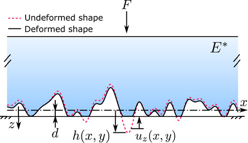
FIGURE 1. Schematic of an elastic half-space with an arbitrarily shaped boundary in purely normal contact with a rigid flat.
Their model can be divided into two parts, a normal contact BEM solver and a mesh-dependent delamination criterion. The former part solves Eqs. 1–4 iteratively with a given contact region Ωc using the conjugate gradient (CG) method (Polonsky and Keer, 1999; Pohrt and Li, 2014). The continuous convolution–fast Fourier transform (CC-FFT) and discrete convolution–fast Fourier Transform (DC-FFT) (Liu et al., 2000; Wang et al., 2020) can be utilized to accelerate the calculation of the normal deflection, uz, for periodic and non-periodic domains, respectively. The resultant p (x, y) is a mixture of tensile and compressive tractions. The later part delaminates the elements where the normal tractions violate the Griffith criterion. Pohrt and Popov (Pohrt and Popov, 2015) creatively developed an analytical solution of SERR (G) using the Boussinesq solutions, and their derivation results in a mesh-dependent form (Pohrt and Popov, 2015)
where
Δx and Δy are mesh sizes in the x and y directions, respectively;
For a given Ωc, the corresponding normal traction, p (x, y), is solved using Algorithm 4 in Appendix A. In each iteration, the potentially detached elements are identified using the normal traction-based criterion in Eq. 6, and are considered as part of Ωnc. Implementation of the above delamination criterion is given in Algorithm 5. This process iterates until the convergence criterion is satisfied. To initiate this iterative process, an initial guess of the contact region
3 Accuracy of Mesh-dependent Strain Energy Release Rate Formula
3.1 Two Classic Crack Problems
The mesh-dependent SERR formula is essential to the previous BEM model, which is responsible for an accurate delamination criterion. Even though their model has been validated in various numerical and experimental studies (Popov et al., 2017; Popov et al., 2021), the accuracy of Eq. 5 has never been proved. In this section, two classic mode-I crack problems are revisited, namely.
• Problem 1: the mode-I periodic collinear cracks of semi-width a with period λ embedded in an infinite space, which are subjected to a tensile normal traction
• Problem 2: a penny-shaped mode-I external crack of radius a embedded in an infinite space, which is subjected to a tensile force F at far end, see Figure 2B. The SERR has the following form (Maugis, 1992; Tada et al., 2000)
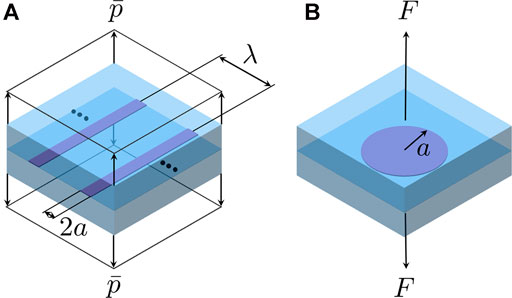
FIGURE 2. Schematics of (A) periodic collinear cracks of period λ with semi-width a subjected to a uniform tensile normal traction
Two problems are all symmetric about its crack plane (see the darker plane in Figure 2). Therefore, two mode-I crack problems are equivalent to the following adhesive contact problems:
• problem 1: a rigid flat and a half-space where half periodic collinear cracks are embedded at the bonding interface;
• problem 2: a rigid flat and a half-space where a half external penny-shaped crack is embedded at the bonding interface.
Because the bonded area (contact area) is known in advance, the CG method given in Algorithm 4 can be used to solve the normal traction, p (x, y), within the bonded area. The SERR is evaluated over the elements at the contact edge using Eq. 5, as well as the VCCT. A short introduction of VCCT is given in Section 3.2.
3.2 Virtual Crack Closure Technique
Virtual crack closure technique (VCCT) is widely used in 2D and 3D finite element model for determining SERR (Krueger, 2004). Consider a simple case where a flexible surface is peeled off from a rigid flat. The normal traction, p, and crack opening displacement, g, over the bonded and debonded surface elements, respectively, are shown in Figure 3. The discontinuous crack opening displacement and contact pressure distribution are due to the constant elements used in the BEM model (uniform normal traction and interfacial gap within each element). As the crack front propagates from A (at load step k) to A′ (at load step k + 1) by a sufficiently fine element size Δx, the following self-similarity can be approximately satisfied:
where the superscript (k) is dropped for the sake of simplicity.
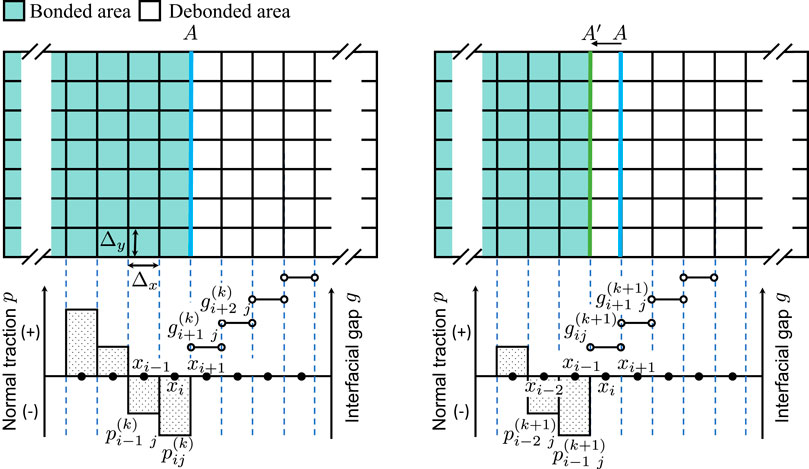
FIGURE 3. Schematics of normal traction and crack opening displacement between a rigid flat and flexible surface at the vicinity of the crack front A (at step k, left) and A′ (at step k + 1, right).
For an arbitrary crack front that cannot be perfectly parallel with the element edges (see Figure 4A for an example), the crack opening displacement in Eq. 9 may have more than one candidate to choose among the closest neighbors of element (i, j). Some methods are proposed in the finite element literature to solve this ambiguity for non-constant (linear, quadratic, etc) elements, and a comprehensive summary of those methods was given by Wu et al. (Wu et al., 2021). For a constant element, we propose the following simple formula
where max (gi j±1, gi±1 j) indicates the maximum crack opening displacement at four closest neighbors of element (i, j). The reason for picking the maximum interfacial gap is because that the edge associated with the maximum interfacial gap is likely the weakest edge for the potential crack to propagate through. Unlike the mesh-dependent SERR formula in Eq. 5 which is based on the Boussinesq solutions (Pohrt and Popov, 2015), VCCT does not rely on any specific analytical solutions so that it is a universal method for evaluating SERR in mode I/II/III, regardless of the material properties (elastic, viscoelastic or elastoplastic) and types of the domain (periodic or non-periodic).
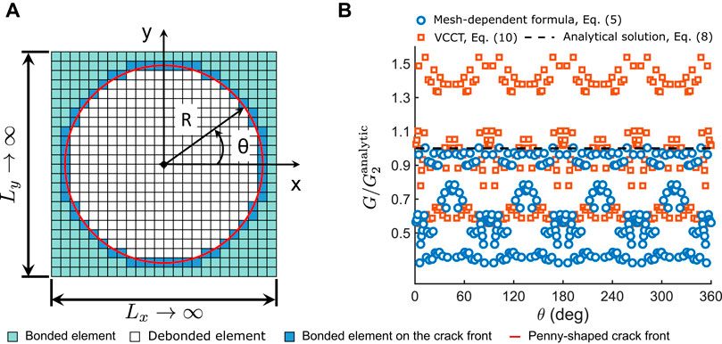
FIGURE 4. (A) Schematic of the mesh grid used in the crack problem 2, and (B) the distribution of SERR, G(θ), at the crack front. Size of the computational domain = 2.5 × 2.5 (mm2), tensile normal load P = 1 (N), a = 1.0 (mm), E* = 1 (MPa). The mesh grid is 128 × 128. Penny-shaped crack is located at the center of the computational domain.
3.3 Strain Energy Release Rate Results
In problem 1, the conforming mesh is used where the element edges are parallel with the crack front (see the straight crack front in Figure 3 as an example). Since the crack problem is in the plane strain condition, the variation of SERR along the crack front is negligible. The SERR determined by VCCT, Eq. 10, associated with three different mesh densities all have excellent agreement with the analytic solution
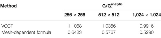
TABLE 1. The SERR of the crack problem 1 determined by mesh-dependent formula, Eq. 5 and VCCT, Eq. 10. Size of computational domain, Ω, is 2.5 × 2.5 (mm2); tensile normal traction
The mesh grid in problem two is non-conforming, since element edges do not always align perfectly with the crack front (see the non-smoothed crack front highlighted in blue in Figure 4A as an example). The distributions of SERR over the circular crack front G(θ), determined by both VCCT and mesh-dependent formula, oscillate about mean levels with the amplitude as high as 50% of
The SERR solved in problem two are summarized in Table 2 where the maximum, average, and standard deviation values of G(θ) all slightly reduce with the increase of the mesh density for both VCCT and mesh dependent formula. This is expected since the smoothness of the crack front is improved at a higher mesh density. However, the accuracy improvement is not significant considering a tremendous increase of computational time. An adaptive mesh scheme localized at the contact edge may be applied to improve the SERR accuracy more efficiently. The mean SERR value determined by VCCT is in good agreement with
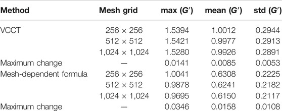
TABLE 2. A summary of
3.4 Remarks
According to Table 1 and 2, we can conclude that the mesh-dependent SERR formula, Eq. 5, cannot accurately estimate SERR associated with the conforming mesh nor the mean SERR value associated with the non-conforming mesh. Its accuracy becomes worse when a finer mesh is used. Pohrt and Popov assumes that the strain energy U due to the delamination of a rectangular area of size Δx × Δy is equivalent to the work done by indenting an elastic half-space within a rectangular area of the same size under the uniform normal traction of σ
This may be correct for evaluating U associated with the crack nucleation within a bonded area, since its neighboring elements are all closed. It is not appropriate, however, to evaluate U of the delaminated element at the crack front where some of its neighboring elements have already been opened.
Surprisingly, the BEM model adopts the mesh-dependent SERR formula has been extensively validated by the analytical solutions and empirical data (Pohrt and Popov, 2015; Popov et al., 2017; Popov et al., 2021). The above-contradicted conclusions may be due to the following reasons:
1). As far as the authors know, the previous BEM model (Pohrt and Popov, 2015) has never been applied to the case where the contact edge is perfectly aligned with the element edge, e.g., adhesive contact in the plane strain/stress condition. Approximately 50% underestimation of SERR by Eq. 5 would result in an earlier crack rest, and cause an overestimation of the contact area. This expectation is confirmed by an example of sinusoidal waviness contact in the plane strain condition given in Section 5.2.
2). Instead of Eq. 5, its equivalent form in terms of normal traction, Eq. 6, is used in the previous BEM model (Pohrt and Popov, 2015). Because
3). Only the elements associated with high peak values of SERR are detached. According to Figure 4B and Table 2, high peak values of SERR associated with different mesh densities all very close to
In a summary, the mesh-dependent formula is less accurate to evaluate the SERR of the elements at the crack front.
4 The Current Model
In this section, a new BEM model is built upon the previous one (Pohrt and Popov, 2015) to fix the inaccurate delamination criterion. Like the previous one discussed in Section 2, the current model can only be applied during the unloading stage which is impossible to capture the snap-in instability. The conjugate gradient method (Algorithm 4) is adopted in the current model to numerically determine the normal traction over a given contact area. The debonding of the contact interface can be divided into two stages, namely, crack nucleation and crack propagation. A composite delamination criterion is developed below to cover both stages.
4.1 Crack Nucleation
Crack nucleation occurs inside the bonded area at the vicinity of closed valleys (dimples). However, VCCT cannot be applied due to the absence of local crack fronts. Cohesive zone modeling (CZM) may be used to circumvent this difficulty. A typical failure of a mode-I cohesive crack consists of two stages, i.e., damage initiation and damage evolution. Before the damage initiation, the cohesive (tensile) normal traction p linearly increases with the interfacial separation δ where the proportionality K is the normal stiffness, see Figure 5. Beyond the damage initiation point (pc, δc), the cohesive interface enters the damage evolution (softening) stage where the normal stiffness degrades gradually until the complete failure is reached at δ = δf.
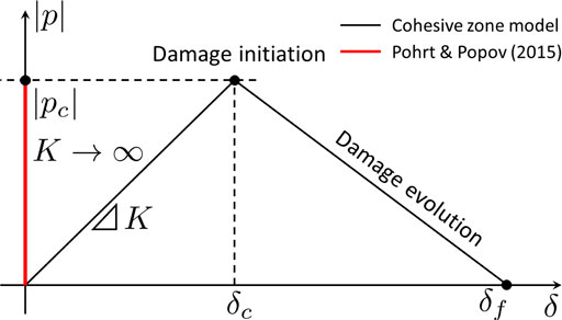
FIGURE 5. Schematic of normal traction p to interfacial gap g relation used in the cohesive zone model.
The normal traction-based delamination criterion, Eq. 6, proposed by Pohrt and Popov (Pohrt and Popov, 2015) is an extrinsic cohesive law (Zhou et al., 2020) where the interfacial separation is strictly zero within the bonded area. Therefore, corresponding p(δ) curve before the damage initiation has an infinite slope K → ∞ (see the red thicker line in Figure 5). The maximum tensile stress, Σ, determined by Eq. 6 could be treated as the critical tensile stress |pc| = Σ at the damage initiation point. For a brittle fracture, catastrophic failure occurs immediately after the damage initiation point. Thus the damage evolution stage could be neglected. Equation 6 also removes the need of assigning multiple parameters (e.g., K, δc and δf) in the phenomenological laws. Algorithm 1 below illustrates how the crack nucleation is implemented in the present model.
4.2 Crack Propagation
The VCCT is used in the present model to calculate the SERR on the contact edge. Because the accuracy of the SERR is deteriorated by the non-smoothed crack front associated with the non-conforming mesh, it is not appropriate to identify the element delamination based on the local SERR values. Taking the stable penny-shaped external crack in Figure 4A as an example. If the delamination of non-conforming elements at the crack front are checked using
To overcome this contradiction, a new crack propagation criterion is proposed based on the mean SERR: mean(G) > w where mean(G) is obtained by averaging the SERR values of all elements at all crack fronts. Once mean(G) > w, only the elements associated with larger SERR values are delaminated so that the mean value of the SERR of the residual bonded elements at the crack front is approximately the same as the work of adhesion w. This delamination process can guarantee that no crack propagation at any individual elements once mean(G) ≤ w is satisfied. The implementation of this delamination process can be found in Algorithm 2.
The algorithm of the present BEM model is almost the same as that given in Algorithm 3.
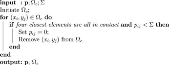
Algorithm 1. (p, Ωc) = CrackNucleation(p, Ωc, Σ) This function determines the crack nucleation based on the Griffith's criterion.
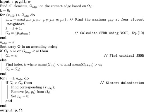
Algorithm 2. (p, Ωc) = CrackPropagation(p, g, w) This function determines the crack propagation based on Griffith's criterion.
5 Results and Discussion
Two classic adhesive contact problems, namely, axisymmetric parabolic contact and sinusoidal waviness contact in the plane strain condition, are revisited by the previous and present models.
5.1 Axisymmetric Parabolic Contact
Consider a rigid parabolic indenter of radius R in a purely normal contact with an elastic half-space under a normal load of F, see the inset in Figure 6B for the schematic. Ignoring the intermolecular attractions outside the contact area, this classic problem can be solved using JKR theory (Johnson et al., 1971; Maugis, 1992). The closed-form solutions of the radius of adhesive contact area, a, and the indentation depth, δ, are
For a given normal load F, the corresponding contact pressure distribution p (r < a) inside the contact area is
and the interfacial gap distribution g (r > a) outside the contact area is
The radius of contact area a(F) and indentation depth δ(F) associated with a sequence of F (increasing from Fmin to 5|Fmin|) are solved by two BEM models and JKR theory where
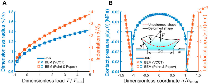
FIGURE 6. (A) Dimensionless contact radius a(F)/a0 and dimensionless indentation δ(F)/δ0; (B) Contact pressure p (x, 0) and interfacial gap g (x, 0) at F = 5|Fmin| where the contact radius is amax. E* = 1 (MPa); Lx = Ly = 2.5 amax; nx = ny = 128; w = 10 × 10–6 (mJ/mm2); R = 10 (mm).
Excellent agreement of a(F) and δ(F) predicted by two BEM models and JKR theory can be found in Figure 6A. A similar agreement of contact pressure distribution p (r < a) and interfacial gap distribution g (r > a) under a normal load of F = 5|Fmin| is shown in Figure 6B. In Table 1 and 2, the SERR determined by a mesh-dependent formula adopted in the previous model is found to be strongly influenced by the mesh size. To investigate how this mesh-dependency influences the results of the previous model, a mesh convergence test is conducted and the relative percentage difference of a and δ with respect to the JKR solutions (i.e., aJKR and δJKR) are given in Table 3. The relative percentage difference of a and δ are negligible. a and δ predicted by both BEM models monotonically converge to the JKR solutions as the mesh density increases. Numerical data in Table 3 confirms that the error brought by the mesh-dependent SERR formula can be neglected in the previous model when the non-conforming mesh is used.
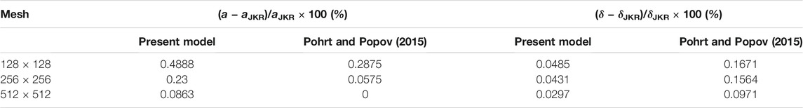
TABLE 3. Results of mesh convergence test of the present and previous BEM models. All key parameters are the same as that give in the caption of Figure 6. Normal load F = 5|Fmin|. aJKR = 0.3478 (mm) and δJKR = 7.4188 × 10⁻³ (mm) are solutions of JKR theory.
5.2 Plane Strain Sinusoidal Waviness Contact
Consider a rigid periodic sinusoidal waviness in the adhesive normal contact with an elastic half-space, see Figure 7. The sinusoidal profile z = h (x, y) has the following geometry
Ignoring the intermolecular attraction outside the contact area, Johnson (Johnson, 1995) solved this problem analytically by superposing a collinear periodic crack problem on a normal non-adhesive sinusoidal waviness contact problem. The contact width 2a within one period λ can be determined from the following non-linear equation
where ψa = πa/λ, p* = πE*Δ/λ, and
where
where x′ is the local coordinate centered at the trough of the sinusoidal waviness, i.e., x′ = x + λ/2, see Figure 7 and l = λ/2 − a. The Green’s function
According to Johnson’s solution, the loading and unloading stages are not reversible. Therefore BEM (VCCT) can only be applied to the unloading stage. As pointed out by Johnson (Johnson, 1995), the sinusoidal waviness bonding interface needs an infinite tensile force to separate if complete contact occurs. Following Johnson’s suggestion, we assume there is a flaw (non-contact region) of width 2bf ≈ 0.11λ which is symmetric about x′ = Nλ where N = 0, ±1, ±2, ⋯. The initial interfacial gap is illustrated using blue dashed line in Figure 7 where the compressible air with negligible internal pressure is trapped within the initial non-contact region. Substituting bf into Eq. 17, the critical average contact pressure
As
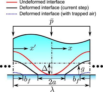
FIGURE 7. Schematic of sinusoidal wavy surface in purely normal contact with a rigid flat.
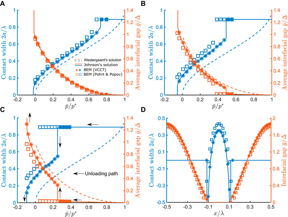
FIGURE 8. Dimensionless contact radius
Figures 8A–C indicates a good agreement in the unloading stage between the numerical solutions of contact width, 2a, and the average interfacial gap,
5.3 Discussion
In Section 3.3, the accuracy of the present model is validated by two classic adhesive contact problems. The previous model is found to be sufficiently accurate only when a non-conforming mesh is used. Up till now, we have shown that 1) VCCT is suitable for evaluating the SERR in the purely normal adhesive contact problem; and 2) the composite delamination criterion is correctly implemented for the crack propagation stage. The crack fronts initially exist in the above two classic problems, thus the crack nucleation part of the composite crack delamination criterion has not been tested yet. The following 3D sinusoidal waviness contact problem is chosen to explore the composite delamination criterion at the crack nucleation stage.
Consider a rigid 3D sinusoidal waviness in a purely normal adhesive contact with an elastic half-space. The sinusoidal surface z = h (x, y) has the following geometry
The contact pair is subjected to an average contact pressure of
where
When the wavy surface is in a complete contact (solid interaction occurs everywhere on z = 0 plane) with the elastic half-space, it is subjected to an average contact pressure
At this instance, crack nucleates and instantaneously propagates until it rests on a stable branch, see Figure 9. The prediction of contact ratio predicted by the two BEM models shows an excellent agreement. As the work of adhesion w increases, the crack nucleation occurs at lower
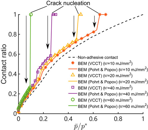
FIGURE 9. Contact ratio to average contact pressure relation associated with multiple work of adhesion w. E* = 1 (MPa), λx = λy = 10 (mm), Δ = 0.1 (mm), nx = ny = 128, and w = 0 ∼ 60 × 10–6 (mJ/mm2).
To explore the influence of mesh size on the solutions of BEM models where crack nucleates inside the bonded area, the sinusoidal waviness contact problem is repeatedly solved using three different mesh densities, and the selected results are given in Table 4. When mesh density is low (e.g., 128 × 128), crack nucleation occurs under the average contact pressure of
which indicates a monotonic increase of Σ with the reduction of element size Δx. For a fixed normal load
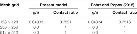
TABLE 4. A mesh convergence study of two BEM models.
In this study, only the purely normal contact problem associated with mode-I crack is modeled. The present model can also be extended to other complex cases in mode-I, II, and III and/or with bi-material interface cracks, e.g., the purely normal contact considering the interfacial friction (Khajeh Salehani et al., 2018) and adhesive friction (Khajeh Salehani et al., 2019). The calculation of tangential surface displacement, as well as new crack propagation and nucleation criterion, must be added to the present model. The former is easily implemented using the Boussinesq-Cerruti solution and FFT. A typical crack propagation criterion in a mixed mode may be written as
where G is the total SERR which is composed of the SERRs in mode-I, II, and III, as well as other parameters, e.g., the mode mixity. SERRs of all modes are determined locally using VCCT. An averaging process is applied to get the mean value of G based on the local value of each element at the contact edge. For an absence of crack fronts, the critical state of interfacial stress may be obtained following the derivation of the mesh-dependent SERR formula where the strain energy contribution due to the tangential load must be added. For better accuracy, the authors suggest developing an empirical approach to curve-fit a phenomenological law for the critical state of interfacial stress at the instance when the crack is nucleated within the bonding area.
6 Conclusion
In this study, a new BEM model is developed upon the previous one proposed by Port and Popov. VCCT is used to evaluate SERR on the edge of the bonding interface. It is a universal tool independent of the material models and domain types. By revisiting two classic crack problems, it is shown that VCCT has better accuracy and weaker mesh-size dependency than the closed-form SERR formula adopted in the previous model. A composite delamination criterion is proposed for crack nucleation and crack propagation. Two classic adhesive contact problems, namely, the axisymmetric parabolic contact and the sinusoidal waviness contact in the plane strain condition, are revisited by the present and previous BEM models. Numerical results predicted by the present model have good agreement with the analytical solutions of both problems. The previous model can achieve a similar accuracy for the axisymmetric parabolic contact where the mesh grid is non-conforming. Once the mesh grid is conforming to the crack front, the accuracy of the previous model is significantly deteriorated, especially at high work of adhesion and high mesh density. In both BEM models, however, the crack nucleation is found to be mesh-dependent which may be solved by introducing an upper limit for the tensile normal traction.
As far as the authors know, the previous model has never been applied to any plane-strain contact problems where the mesh grid is strictly conforming to the crack front, the comparisons and conclusions made upon the results of the previous model are still valid. The authors recommend replacing the mesh-dependent SERR formula with the VCCT in the adhesive contact models for better accuracy, weaker mesh-dependency, and broader applications.
Data Availability Statement
The raw data supporting the conclusions of this article will be made available by the authors, without undue reservation.
Author Contributions
YX and RZ contributed to the conception and design of the study. YX performed the numerical analysis. YX wrote the first draft of the manuscript. All authors contributed to manuscript revision, read, and approved the submitted version.
Funding
This work is supported by the National Natural Science Foundation of China (Grant No. 52105179).
Conflict of Interest
The authors declare that the research was conducted in the absence of any commercial or financial relationships that could be construed as a potential conflict of interest.
Publisher’s Note
All claims expressed in this article are solely those of the authors and do not necessarily represent those of their affiliated organizations, or those of the publisher, the editors, and the reviewers. Any product that may be evaluated in this article, or claim that may be made by its manufacturer, is not guaranteed or endorsed by the publisher.
Footnotes
1Several typos are found in Johnson’s original derivation (Johnson, 1995). The contact pressure p(x) is decomposed into p′(x) and p″(x) terms. The former term is Westergaard solution, but the square root is missing in Eq. 5 in Ref. (Johnson, 1995). The latter part contains an extra negative sign in front of
References
Barber, J. R. (2003). Bounds on the Electrical Resistance between Contacting Elastic Rough Bodies. Proc. R. Soc. Lond. A. 459 (2029), 53–66. doi:10.1098/rspa.2002.1038
Bugnicourt, R., Sainsot, P., Dureisseix, D., Gauthier, C., and Lubrecht, A. A. (2018). FFT-based Methods for Solving a Rough Adhesive Contact: Description and Convergence Study. Tribol Lett. 66 (1), 29. doi:10.1007/s11249-017-0980-z
Carbone, G., and Mangialardi, L. (2008). Analysis of the Adhesive Contact of Confined Layers by Using a Green's Function Approach. J. Mech. Phys. Sol. 56 (2), 684–706. doi:10.1016/j.jmps.2007.05.009
Carbone, G., Pierro, E., and Recchia, G. (2015). Loading-unloading Hysteresis Loop of Randomly Rough Adhesive Contacts. Phys. Rev. E 92 (6), 62404. doi:10.1103/physreve.92.062404
Carbone, G., Scaraggi, M., and Tartaglino, U. (2009). Adhesive Contact of Rough Surfaces: Comparison between Numerical Calculations and Analytical Theories. Eur. Phys. J. E 30 (1), 65–74. doi:10.1140/epje/i2009-10508-5
Ciavarella, M. (2015). Adhesive Rough Contacts Near Complete Contact. Int. J. Mech. Sci. 104, 104–111. doi:10.1016/j.ijmecsci.2015.10.005
Ciavarella, M., Xu, Y., and Jackson, R. L. (2018). Some Closed-form Results for Adhesive Rough Contacts Near Complete Contact on Loading and Unloading in the Johnson, Kendall, and Roberts Regime. J. Tribology 140 (1), 11402. doi:10.1115/1.4036915
Ciavarella, M., Xu, Y., and Jackson, R. L. (2019). The Generalized Tabor Parameter for Adhesive Rough Contacts Near Complete Contact. J. Mech. Phys. Sol. 122, 126–140. doi:10.1016/j.jmps.2018.08.011
Feng, J. Q. (2000). Contact Behavior of Spherical Elastic Particles: a Computational Study of Particle Adhesion and Deformations. Colloids Surf. A: Physicochemical Eng. Aspets 172 (1), 175–198. doi:10.1016/s0927-7757(00)00580-x
Ghanbarzadeh, A., Faraji, M., and Neville, A. (2020). Deterministic normal Contact of Rough Surfaces with Adhesion Using a Surface Integral Method. Proc. R. Soc. A. 476 (2242), 20200281. doi:10.1098/rspa.2020.0281
Greenwood, J. A. (1997). Adhesion of Elastic Spheres. Proc. R. Soc. Lond. A. 453 (1961), 1277–1297. doi:10.1098/rspa.1997.0070
Greenwood, J. A., and Johnson, K. L. (1998). An Alternative to the Maugis Model of Adhesion between Elastic Spheres. J. Phys. D: Appl. Phys. 31 (22), 3279–3290. doi:10.1088/0022-3727/31/22/017
Greenwood, J. A., and Johnson, K. L. (1981). The Mechanics of Adhesion of Viscoelastic Solids. Philosophical Mag. A 43 (3), 697–711. doi:10.1080/01418618108240402
Greenwood, J. A. (2017). Reflections on and Extensions of the Fuller and Tabor Theory of Rough Surface Adhesion. Tribology Lett. 65 (4), 1–12. doi:10.1007/s11249-017-0938-1
Jin, F., Wan, Q., and Guo, X. (2016). A Double-Westergaard Model for Adhesive Contact of a Wavy Surface. Int. J. Sol. Structures 102-103, 66–76. doi:10.1016/j.ijsolstr.2016.10.016
Jin, F., and Yue, D. (2020). An Equivalent Indentation Method for the External Crack with a Dugdale Cohesive Zone. J. Elast 141 (1), 31–49. doi:10.1007/s10659-020-09773-w
Johnson, K. L., Kendall, K., and Roberts, A. D. (1971). Surface Energy and the Contact of Elastic Solids. Proc. R. Soc. Lond. A. 324 (1558), 301–313. doi:10.1098/rspa.1971.0141
Johnson, K. L. (1995). The Adhesion of Two Elastic Bodies with Slightly Wavy Surfaces. Int. J. Sol. Structures 32, 423–430. doi:10.1016/0020-7683(94)00111-9
Khajeh Salehani, M., Irani, N., Müser, M. H., and Nicola, L. (2018). Modelling Coupled normal and Tangential Tractions in Adhesive Contacts. Tribology Int. 124, 93–101. doi:10.1016/j.triboint.2018.03.022
Khajeh Salehani, M., Irani, N., and Nicola, L. (2019). Modeling Adhesive Contacts under Mixed-Mode Loading. J. Mech. Phys. Sol. 130, 320–329. doi:10.1016/j.jmps.2019.06.010
Khajeh Salehani, M., van Dokkum, J. S., Irani, N., and Nicola, L. (2020). On the Load-Area Relation in Rough Adhesive Contacts. Tribology Int. 144, 106099. doi:10.1016/j.triboint.2019.106099
Koiter, W. T. (1959). An Infinite Row of Collinear Cracks in an Infinite Elastic Sheet. Ing. Arch. 28 (1), 168–172. doi:10.1007/bf00536108
Krueger, R. (2004). Virtual Crack Closure Technique: History, Approach, and Applications. Appl. Mech. Rev. 57 (2), 109–143. doi:10.1115/1.1595677
Liu, S., Wang, Q., and Liu, G. (2000). A Versatile Method of Discrete Convolution and FFT (DC-FFT) for Contact Analyses. Wear 243 (1), 101–111. doi:10.1016/s0043-1648(00)00427-0
Maugis, D. (1992). Adhesion of Spheres: the JKR-DMT Transition Using a Dugdale Model. J. Colloid Interf. Sci. 150, 243–269. doi:10.1016/0021-9797(92)90285-t
Maugis, D., and Barquins, M. (1978). Fracture Mechanics and the Adherence of Viscoelastic Bodies. J. Phys. D: Appl. Phys. 11 (14), 1989–2023. doi:10.1088/0022-3727/11/14/011
Menga, N., Afferrante, L., and Carbone, G. (2016). Adhesive and Adhesiveless Contact Mechanics of Elastic Layers on Slightly Wavy Rigid Substrates. Int. J. Sol. Structures 88-89, 101–109. doi:10.1016/j.ijsolstr.2016.03.016
Müser, M. H. (2016). A Dimensionless Measure for Adhesion and Effects of the Range of Adhesion in Contacts of Nominally Flat Surfaces. Tribology Int. 100, 41–47. doi:10.1016/j.triboint.2015.11.010
Pastewka, L., and Robbins, M. O. (2014). Contact between Rough Surfaces and a Criterion for Macroscopic Adhesion. Proc. Natl. Acad. Sci. USA. 111 (9), 3298–3303. doi:10.1073/pnas.1320846111
Persson, B. N. J. (2002). Adhesion between an Elastic Body and a Randomly Rough Hard Surface. Eur. Phys. J. E 8 (4), 385–401. doi:10.1140/epje/i2002-10025-1
Pohrt, R., and Li, Q. (2014). Complete Boundary Element Formulation for normal and Tangential Contact Problems. Phys. Mesomech 17 (4), 334–340. doi:10.1134/s1029959914040109
Pohrt, R., and Popov, V. L. (2015). Adhesive Contact Simulation of Elastic Solids Using Local Mesh-dependent Detachment Criterion in Boundary Elements Method. Facta Universitatis, Ser. Mech. Eng. 13 (1), 3–10.
Polonsky, I. A., and Keer, L. M. (1999). A Numerical Method for Solving Rough Contact Problems Based on the Multi-Level Multi-Summation and Conjugate Gradient Techniques. Wear 231 (2), 206–219. doi:10.1016/s0043-1648(99)00113-1
Popov, V. L., Li, Q., Lyashenko, I. A., and Pohrt, R. (2021). Adhesion and Friction in Hard and Soft Contacts: Theory and experiment. Friction 1–19. doi:10.1007/s40544-020-0482-0
Popov, V. L., Pohrt, R., and Li, Q. (2017). Strength of Adhesive Contacts: Influence of Contact Geometry and Material Gradients. Friction 5 (3), 308–325. doi:10.1007/s40544-017-0177-3
Rey, V., Anciaux, G., and Molinari, J.-F. (2017). Normal Adhesive Contact on Rough Surfaces: Efficient Algorithm for FFT-Based BEM Resolution. Comput. Mech. 60 (1), 69–81. doi:10.1007/s00466-017-1392-5
Tada, H., Paris, P. C., and Irwin, G. R. (2000). The Stress Analysis of Cracks Handbook. Third Edition. New York: ASME Press.
Wang, A., Zhou, Y., and Müser, M. H. (2021). Modeling Adhesive Hysteresis. Lubricants 9 (2), 17. doi:10.3390/lubricants9020017
Wang, Q. J., Sun, L., Zhang, X., Liu, S., and Zhu, D. (2020). FFT-based Methods for Computational Contact Mechanics. Front. Mech. Eng. 6. doi:10.3389/fmech.2020.00061
Wu, H., Settgast, R. R., Fu, P., and Morris, J. P. (2021). An Enhanced Virtual Crack Closure Technique for Stress Intensity Factor Calculation along Arbitrary Crack Fronts and the Application in Hydraulic Fracturing Simulation. Rock Mech. Rock Eng. 1–15. doi:10.1007/s00603-021-02428-9
Xie, D., and Biggers, S. B. (2006). Strain Energy Release Rate Calculation for a Moving Delamination Front of Arbitrary Shape Based on the Virtual Crack Closure Technique. Part I: Formulation and Validation. Eng. Fracture Mech. 73 (6), 771–785. doi:10.1016/j.engfracmech.2005.07.013
Xu, Y., Jackson, R. L., and Marghitu, D. B. (2014). Statistical Model of Nearly Complete Elastic Rough Surface Contact. Int. J. Sol. Structures 51 (5), 1075–1088. doi:10.1016/j.ijsolstr.2013.12.005
Xu, Y., and Jackson, R. L. (2018). Periodic Contact Problems in Plane Elasticity: The Fracture Mechanics Approach. J. Tribology-Transactions Asme 140 (1), 11404. doi:10.1115/1.4036920
Xu, Y., Rostami, A., and Jackson, R. L. (2015). Elastic Contact between a Geometrically Anisotropic Bisinusoidal Surface and a Rigid Base. J. Tribology 137 (2), 21402. doi:10.1115/1.4029537
Zhou, R., Chen, H.-M., and Lu, Y. (2020). Mesoscale Modelling of concrete under High Strain Rate Tension with a Rate-dependent Cohesive Interface Approach. Int. J. Impact Eng. 139, 103500. doi:10.1016/j.ijimpeng.2020.103500
Appendix A. BEM algorithm
In this section, the algorithm of the previous model developed by Pohrt and Popov (Pohrt and Popov, 2015) is given below. The tolerance and maximum number of iteration are hard programmed as εc = 1 × 10⁻⁵ and nmax = 1000 for both BEM models.
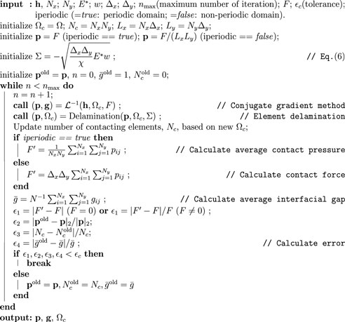
ALGORITHM 3. BEM (Pohrt & Popov). The algorithm for boundary element method of linear elastic purely normal contact. This algorithm is adapted from the one given by Pohrt and Popov (Pohrt and Popov, 2015).
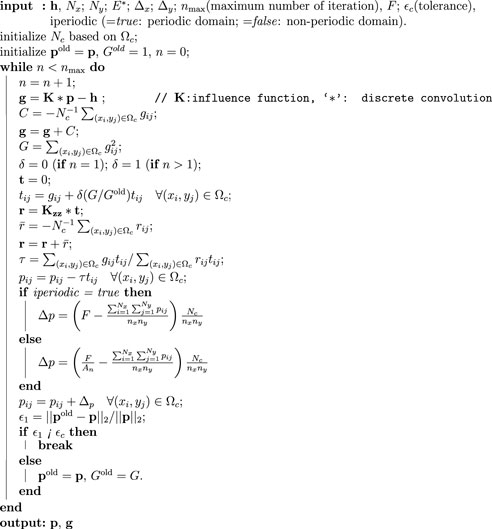
ALGORITHM 4.
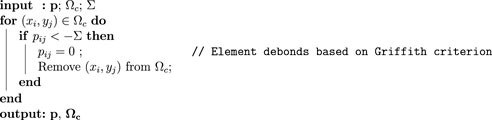
ALGORITHM 5. (p, Ωc) = Delamination(p, Ωc, Σ). Mesh dependent local detachment criterion
Keywords: adhesion, fracture, boundary element method, virtual crack closure technique, contact mechanics
Citation: Xu Y and Zhou R (2021) Adhesive Boundary Element Method Using Virtual Crack Closure Technique. Front. Mech. Eng 7:754782. doi: 10.3389/fmech.2021.754782
Received: 07 August 2021; Accepted: 20 September 2021;
Published: 28 October 2021.
Edited by:
Nicola Menga, Politecnico di Bari, ItalyCopyright © 2021 Xu and Zhou. This is an open-access article distributed under the terms of the Creative Commons Attribution License (CC BY). The use, distribution or reproduction in other forums is permitted, provided the original author(s) and the copyright owner(s) are credited and that the original publication in this journal is cited, in accordance with accepted academic practice. No use, distribution or reproduction is permitted which does not comply with these terms.
*Correspondence: Yang Xu, Yang.Xu@hfut.edu.cn