 Rosa Mendaza-DeCal
 Salvador Peso-Fernandez
 Jesus Rodriguez-Quiros
95% of researchers rate our articles as excellent or good
Learn more about the work of our research integrity team to safeguard the quality of each article we publish.
Find out more
ORIGINAL RESEARCH article
Front. Mech. Eng. , 26 August 2021
Sec. Digital Manufacturing
Volume 7 - 2021 | https://doi.org/10.3389/fmech.2021.693436
This article is part of the Research Topic Global Excellence in Digital Manufacturing: Europe View all 5 articles
Total limb amputation is quite common in small animals, although most of the indicated pathologies do not need such a restrictive procedure. Exo-endoprosthesis is a suggested alternative for the enhancement of the biomechanical situation of these patients. 3D printing of the internal part of exo-endoprostheses in polyether ether ketone (PEEK) is evaluated. Two different shapes of this internal part—one for radius’ and the other for cylindrical medullary cavities—were assessed. Proper PEEK temperature settings for 3D printing, the internal part of exo-endoprostheses, by fused filament fabrication (FFF) were obtained. Printing trials were carried out for different dimensions and printing orientation of these parts to achieve the best bone anchorage and thread strength outcomes. Pull-off strength tests for different surfaces of the internal part were performed with a best outcome for positive surfaces. All printed internal parts were inserted in canine tibiae and radii for an ex vivo assessment of bone anchorage and thread strength parameters. The best printing results were obtained at 410 and 130°C of the nozzle and bed temperatures, respectively. Also, a positive correlation was observed between the printing code, quality, and take-off time, while inverse correlation was shown between the take-off and the printing code, or quality, just like the print-bed temperature and the printing code. The positive surfaces had the best pull-off strength outcomes. Excellent bone anchorage and thread strength outcomes were obtained for one variant of each internal part shape. Designed devices had shown good threaded rod’s fitting inside the PEEK plug and perfect bone anchorage of the PEEK plug for tibiae and radii. In addition, iteration of manufacturing PEEK small devices by FFF technology has been shown due to small standard deviation of most variants.
Total amputation of a limb is commonly performed in small animals. Limb pathologies that indicated to choose this procedure are neoplasia, severe trauma to any tissues of a limb, peripherical nerve pathologies, ischemic necrosis, osteomyelitis, unmanageable osteoarthrosis, or severe congenital limb malformation. However, when deciding to perform an amputation, some contraindications have been found: severe neurological or orthopedic pathologies in the remaining limbs, and extreme obesity (Séguin and Weigel, 2012). Total limb amputations are associated with quite remarkable kinematic and kinetic changes in remaining limbs (Galindo-Zamora et al., 2016). Those changes are greater for animals with a thoracic limb amputation than with a pelvic one (Galindo-Zamora et al., 2016). The absence of a limb creates mobility and endurance limitations; it also increases metabolic demands, weight gain and weight-bearing instability, chronic neck and back pain, and the probability of premature euthanasia (Mich, 2014).
For contraindicated cases of full-limb amputation or when owners are reluctant for such a procedure to be carried out, a distal partial limb amputation could be considered for replacing that injured portion with a prosthetic device (Fitzpatrick et al., 2011; Séguin and Weigel, 2012; Farrell et al., 2014; Mich, 2014; Phillips et al., 2017; Golachowski et al., 2019; Wendland et al., 2019). Prosthetic devices could be a socket prosthesis or exo-endoprosthesis (Mich, 2014). Recently, more socket prosthesis studies have appeared with variable results about owner’s satisfaction and complications related to these devices (Phillips et al., 2017; Wendland et al., 2019). Some ruminant patients have also been reported (Desrochers et al., 2014). Socket prosthesis advantages are limited to avoiding a new surgical procedure, and the device could be removed easily when required. Some complications for this type of prosthesis are skin–prosthesis interface issues (poor attachment, stump pain, skin sores, swelling, dermatitis, and pressure necrosis), loss of mechanical integrity, repeated adjustments for patient’s whole life, and perception of foreign body (Phillips et al., 2017; Wendland et al., 2019).
A good prognosis and absence of pain in the remainder limb have been reported for the exo-endoprosthesis option. Due to its insertion in the medullary cavity of long bones, all the disadvantages of a socket prosthesis are avoided. Besides, better proprioception, no delay in load transfer, comfort, and energetic efficiency all have been described (Fitzpatrick et al., 2011; DeVasConCellos et al., 2012; Pitkin, 2013; Phillips et al., 2017). Exo-endoprosthesis complications have been reported, such as device failure, aseptic loss, marsupialization or skin breakdown, avulsion, and infection (Drygas et al., 2008; Fitzpatrick et al., 2011; DeVasConCellos et al., 2012; Golachowski et al., 2019). There are published clinical reports for exo-endoprosthesis for different animal species (Drygas et al., 2008; Fitzpatrick et al., 2011; Golachowski et al., 2019) or experimental models (Hall, 1976; Pitkin, 2013; Farrell et al., 2014). All these devices are of press-fit designs, while no screw-type endoprosthesis has been described for clinical cases as in the human medicine field (Brånemark et al., 2014).
All of the reported animal exo-endoprostheses used different metal alloys as the main material (Drygas et al., 2008; Fitzpatrick et al., 2011; DeVasConCellos et al., 2012; Farrell et al., 2014; Golachowski et al., 2019). Two of these are fabricated by additive manufacturing for metal materials using direct metal laser sintering technology (DMLS) (DeVasConCellos et al., 2012; Golachowski et al., 2019). In human medicine, a similar situation occurred, although there is greater variety of reports published on exo-endoprostheses using both press-fit and threaded devices (Pitkin, 2013; Thesleff et al., 2018). Only a fused filament fabrication (FFF) in a PA680 endoprosthesis part has been patented and published with some experimental outcomes for human patients (Lathers and La Belle, 2016); however, no clinical cases have been registered.
Additive manufacturing is a cheaper option than traditional manufacturing (Atzeni and Salmi, 2012) and permits the fabrication of patient-specific devices (Worth et al., 2019). FFF technology is the cheapest brand of additive manufacturing (Hopkinson and Dicknes, 2003) and permits choosing from among a variety of polymeric materials for producing functional final parts (Ligon et al., 2017; Salentijn et al., 2017). Some of these polymers are considered high-performance thermoplastics with excellent mechanical properties while still being biocompatible, as those occurring with polyether ether ketone (PEEK) (Kurtz, 2019). Nevertheless, the use of FFF technology for manufacturing prosthesis in veterinary medicine has not been reported yet, which is strange because surgeries are paid by pet owners and the advancement of the field depends on their budget. Nowadays—as aforementioned—metal-made devices are the only option for exo-endoprotheses. In addition, they are still quite expensive for most owners, which reduces the possibilities of these devices to be chosen as a solution in the future and hinders the investigation about this treatment technique.
PEEK is a semicrystalline homopolymer, which—in its raw bulk form—is biocompatible, but also bioinert for traumatology, neurosurgery, and craniomaxillofacial fields in human medicine (Kurtz, 2019). PEEK appeared as an option in the prosthetic field because of its mechanical properties, especially its weight-bearing and wear strength. In addition, its mechanical stiffness—when compared with metal materials—is closer to the bone’s, which would avoid or reduce stress shielding caused by the high stiffness of implanted metallic material (Ramakrishna et al., 2001; Evans and Gregson, 1998; Kurtz and Devine, 2007; Panayotov et al., 2016; Kurtz, 2019). Being a biocompatible and bioinert polymer means it could act as a support or substitution of an anatomical part and has direct contact with surrounding tissue but will not form a chemical bond with it (Kurtz, 2019). Therefore, some PEEK contacting devices use different surface geometries to form macro-mechanical interlocks between the bone and the device (Kurtz, 2019). Another option might be using a composite of PEEK mixed with other bioactive materials (Yu et al., 2005; Durham et al., 2016; Zhang et al., 2018; Kurtz, 2019).
Considering all the above information, quadrupedal small animal patients support much less weight for each limb than a bipedal human being and also have a lower elastic modulus of long bones (Reilly et al., 1974; Saha et al., 1977; Keller et al., 1990; Hoffmeister et al., 2000; Autefage et al., 2012). Hence, the material selected for exo-endoprosthesis devices could be reconsidered from being metals to being suitable polymers (such as those mentioned above). Furthermore, regarding the customization and reducing final consumer’s cost, the option of 3D-printed PEEK devices is reinforced. The purpose of this study was to establish 3D-print conditions for designing and manufacturing PEEK exo-endoprosthesis and to describe the principal dimensions for a proper exo-endoprosthesis’ bone anchorage.
For endoprosthesis insertion trials, two different long bones were selected–tibiae and radii–both from canine specimens that had been euthanized for reasons unrelated to this study. This study was approved by the Animal Care and Use Committee of the Veterinary Faculty of Madrid (nº 05/2019, Clinical Veterinary Hospital, the University Complutense of Madrid, Spain). Bones were differently prepared depending on which endoprosthesis material—polylactic acid (PLA) or PEEK —was going to be inserted. Regarding PLA endoprostheses, a dry bone was chosen. On the other hand, fresh bones were used to test the PEEK-endoprosthesis insertion. For both bone-preparation types, soft tissue was removed; after that, each bone differed in its preparation. The dry bone was a bone which had been boiled for 3 h and then stored at room temperature. The fresh bone was immediately stored inside a vacuum bag in a freezer at −18°C (GTL 6105–21 Liebherr, Bulle, Switzerland) until endoprosthesis insertion.
Bones were classified by their medullary cavity (MC) diameter. One measurement was obtained for tibiae MCs, due to its circular-alike transversal section. Regarding the radii measurements, two MC diameters could be differentiated: a craniocaudal MC diameter (MC short diameter) and a mediolateral MC diameter (MC large diameter), because of its elliptical-alike transversal section. Both could be measured using a mediolateral and craniocaudal traditional radiograph, respectively.
The PEEK endoprosthesis was designed in a computer-aided design (CAD) program (SolidWorks 2018; SolidWorks Corp., Waltham, MA, United States) and was composed of two main parts: a PEEK plug (Figure 1) and a surgical metallic threaded rod. This composed device was patented (De Cal et al., 2020). The PEEK plug comprised a base, an “umbrella,” neck, and a stem (De Cal et al., 2020). Most sections of the endoprosthesis were constant in morphology during testing, but all sections could vary their size proportionally depending on the general dimension of the bone into which the prosthesis was inserted.
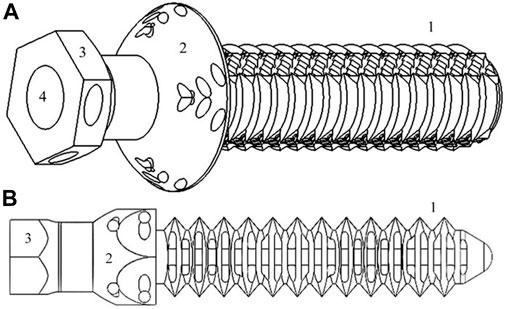
FIGURE 1. Simplified representation of tibiae [(A), 16.54*50.21*14.72 mm3] and radii [(B), 11.25*50.23*10.01 mm3] PEEK plug of endoprosthesis designed in SolidWorks: (C) stem-section, (D) “umbrella,” (E) base, and (F) inner cavity where surgical metal threaded rod is screwed.
Two types of PEEK-endoprosthesis designs were inserted depending on which type of bone would be the recipient (tibia or radius) (Figure 1). Both types showed different stem external diameters—one measurement in the tibiae plug (named “External Ø” at subsequent tables) and two in the radii model (named “Large- and Short-external Ø,” respectively, at following tables)—stem length, and two cylindrical internal cavity diameters (named “Proximal and Distal cavity Ø,” respectively, at succeeding tables) (De Cal et al., 2020). Regarding the radii plug, the two stem external diameters were related to the two radius’ MC diameters mentioned above. Hence, the radii plug stem had an elliptical transversal section, and the tibiae plug stem had a cylindrical transversal section. The stem length is defined as the distance between the “umbrella” and the end of the stem. Proximal and distal cavities are the above and below areas of the plug inner cavity in relation to its proximity to the animal trunk when the endoprosthesis was inserted in the bone. The proximal cavity diameter was always smaller than that of the distal one. These parameters were set on SW regarding the bone diameters—at the beginning—and measured at the 3D-printed models.
Some modifications were made on the “umbrella” and stem sections. The “umbrella” section was made with two versions: i) circular base and ii) hexagonal base, depending on the printing orientation—vertical or horizontal, respectively. The stem was made with five different surface versions to improve the anchorage at the endoprosthesis–bone interface. These versions were ridges, flanges, macroporous holes, prismatic holes, cylindrical holes, and hybrid solution composed of ridges or flanges and cylindrical holes (Figure 2). Regardless of the many different finishing touches of the pieces, two different groups are clearly distinguished: negative surfaces, which preserved the original stem diameter, and positive surfaces, which added extra millimeters to the final stem diameter.
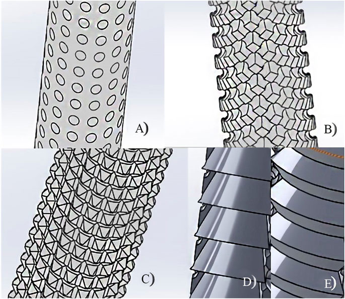
FIGURE 2. Different surfaces of the PEEK-plug stem: (A) macroporous holes, (B) cylindrical holes, (C) prismatic holes, (D) flanges, and (E) ridges.
Bone anchorage for the different stem surfaces was estimated by inserting PLA-endoprosthesis into the dry bone. For a preliminary bone anchorage assessment, a comparison of the maximum pull-off strength until failure of the endoprosthesis–bone interaction was recorded for each surface group. The assemblies were firmly affixed at a workbench with an own-designed 3D-printed PLA clamp. On this workbench, a metal lever was used to connect the endoprosthesis–bone assembly to a M10-size threaded rod—with a pitch of 1.5 mm—attached to a stepper motor, which applied the weight progressively by screwing the M10 rod inside the lever until failure. The applied force was recorded by a commercial dynamometer which was previously calibrated with weights from 1 to 20 kg. The dynamometer was located between the assembly and the lever. The tests were performed at a rate of 0.08 mm/s. At least three repetitions for negative and positive surface groups were tested, respectively. Due to the use of the dry bone, no osseointegration could be evaluated.
In the tibiae PEEK plug assessment, five variant groups were created depending on the surface type (flange, P; ridges, C) and on slightly changeable dimensions in the external diameter and endoprosthesis’ inner cavity. Tibiae endoprostheses were inserted in bones with a similar MC diameter. At least four repetitions were tested for each variant.
On the other hand, for the radii PEEK-endoprosthesis evaluation, four variants were grouped depending on the radius’ MC, which had slight dimension changes. In these endoprostheses, slight variations on the short external and inner cavity diameters were designed considering that the recipient radii would have a similar craniocaudal MC size. At least four repetitions were tested for each variant.
Plugs of the endoprostheses were printed in two different filament materials: PLA (Ivony White 1,000 g spool and 1.75 mm filament diameter, SmartMaterials, Jaén, Spain) and PEEK (Natural 500 g spool and 1.75 mm filament diameter 3D4Makers, Amsterdam, Netherlands). PLA is a thermoplastic polyester and biodegradable polymer commonly used in 3D printing for prototyping or for a small range of finished products; it is cheaper than PEEK. PLA has no negligible mechanical properties and can be reabsorbed by the organism; however, it induces an inflammatory response (Koëter et al., 2006; Ruiz Marín et al., 2009; Chacón et al., 2017). PEEK is a biocompatible inert thermoplastic polymer with high mechanical properties. Nevertheless, PEEK has been used to prove that these mechanical properties are inferior to those of injection molding—even if printed models have 100% infill—but that reduction was still within the canine cortical bone ranges (Saha et al., 1977), or closer than metallic materials (Niinomi, 1998; Wu et al., 2014; Arif et al., 2018). Furthermore, when porosity has been incorporated into models, it was identified as an effective approach to improve PEEK osseointegration (Evans et al., 2015).
Both filaments were stored in a special ziplock multilayered bag with a special ethylene vinyl alcohol copolymer (EVOH) barrier film and silica desiccant sachets provided by the filament supplier. Otherwise, before the printing process with PEEK—and following the recommended protocols by Wu et al. (2014) and the filament manufacturers—spools were dried at 150°C for 3 h in a dry-heat oven (Selecta, Abrera, Barcelona, Spain).
PLA-endoprosthesis was printed by a Titan 300 printer (Abax Innovation Technologies, Villanueva de la Cañada, Madrid, Spain) based on FFF technology. The printer had a brass nozzle of 0.4 mm diameter. The printer reached a nozzle temperature of up to 260°C, a bed temperature of up to 120°C, and a partially closed chamber without inside temperature control. PLA-endoprosthesis anchorage of dry tibiae was estimated as described above. Before printing, 3D virtual models were sliced by Simplify 3D software (Cincinnati, OH, United States).
PEEK-endoprosthesis was printed by FunMat HT (INTAMSYS, Shanghai, China), which is also a printer based on FFF technology. The printer has a nozzle with 0.4 mm diameter, and the material of the nozzle was changed during the study among brass, stainless steel, and hardened steel. This printer reaches a nozzle temperature of up to 450°C, a bed temperature of up to 160°C, and a chamber temperature of up to 90°C. Before printing, 3D virtual models were sliced by Simplify 3D software.
Printing parameters were constant during the setting of thermal and ventilation parameters. The latter were established for optimal printing results of our PEEK filament and endoprosthesis volume for this study—tibiae model volume of 16.54*50.21*14.72 mm3 and radii model volume of 11.25*50.23*10.01 mm3 concerning x, y, and z of the printing bed, respectively. For determining best temperature settings, the empirical method had allowed us to define parameters that enabled finishing a print process with the best quality and accuracy of the test models. At least four repetitions were tested for each orientation. The cooling parameter was determined comparing surface topography and the presence or not of delamination.
Three different PEEK-printing orientations for the tibial endoprostheses were carried out considering the main mechanical forces: vertical (V), opposite vertical (V+), and horizontal (H) (Figure 3). Vertical orientation was placed with the endoprosthesis longitudinal axis perpendicular to the printing bed and the plug’s base in contact with the bed. The opposite vertical orientation was placed with the endoprosthesis vertical axis perpendicular to the printing bed and the stem in contact with the bed. The horizontal orientation was placed with the endoprosthesis vertical axis parallel to the printing bed. Printing parameters of each printing orientation are shown in Table 1.
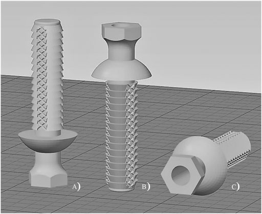
FIGURE 3. Printing orientation of tibiae endoprosthesis’ plug: (A) vertical; (B) opposite vertical; and (C) horizontal.
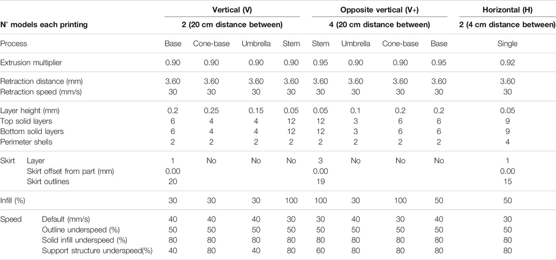
TABLE 1. Printing parameters for different printing orientation of the PEEK-plugs.
Furthermore, a 3D printing–specific liquid fixative (Dimafix, DIMA 3D, Valladolid, Spain) was applied to the cold print bed immediately before each PEEK-printing, for better adhesion of the material. A preheat of the chamber and the build bed temperatures were set and left to stabilize for at least 30 min before starting any printing.
Thermal parameters for printing PEEK were correlated to the global print job (which was defined by the printing code and the printing quality) or, otherwise, led to the take-off of the print product before finishing. The printing code was defined as the percentage of the total g-code in which printing was concluded with reasonable definition. Percentage was assessed using the followed index: from 0 (not concluded) to 100% (fully concluded). Printing quality was defined as the accuracy of the printed device to the designed model in SolidWorks (SW) and layer-to-layer union (how easy it is to separate layers just by applying hand pressure). Printing quality was assessed using the following index: 0 = very bad quality, 1 = bad quality, 2 = medium quality, 3 = good quality, 4 = quite good quality, and 5 = very good quality. The take-off variable was fundamentally defined by warping. Warping prevented the printout from concluding for most of the cases; nevertheless, a few prints were able to be completed, although all of them were of low quality. This parameter was assessed using the following index: from 0 (no take-off) to 1 (total take-off).
After printing the endoprostheses, measurements of the stem were determined with a metric digital caliper (series 1,109, INSIZE, Jiangsu, China). To establish the real diameters of the cylindrical internal cavity, drill bits of different sizes were used until the drill bit felt tight on entry.
Fresh bones were used to test the PEEK-endoprosthesis insertion. The MC’s diameters for PEEK plug implantation varied around 9 and 5–8 mm for the tibia’s and radius’ craniocaudal MC diameters, respectively. Nevertheless, the radius’ mediolateral MC diameter had such variability (7–13 mm approximately) because of which we were unable to use this measurement for gathering the samples.
Bones were perpendicularly cut to the bone’s longitudinal axis above the distal epiphysis. Short radii and tibiae diameters were drilled by a drill bit with a 9- and 6-mm diameter, respectively. Two own-designed 3D-printed PLA surgical guides were used to make a perpendicular cut and align the drilling. One adapted to the radius’ shape and the other adapted to the tibia’s shape. The plug insertion into the bone was made with soft blows of a hammer. Once the plug was already inserted, a stainless steel 316 threaded rod was gently screwed using a locknut inside the plastic plug, and a 30-mm length was left outside the plug. The threaded rods were made from stainless steel and their diameters were from 3 to 6 mm, depending on if it was screwed in radii or the tibiae plug model. At least four tibiae or radii were used in endoprosthesis insertion for each tibiae or radii endoprosthesis-variant. In addition, to evaluate the bone anchorage and thread strength of the radii endoprostheses, the 8.1/6 variant was divided into six subcategories, depending on the short external and proximal cavity Ø values designed in SW. At least three repetitions were tested for each subcategory.
The outcomes of PEEK-endoprosthesis insertion were estimated based on its anchorage to the fresh bone and the thread strength of the threaded rod. The bone anchorage parameter was defined as the resistance of the endoprosthesis to be inserted in bone MC. Bone anchorage was assessed using the following index: 0, for endoprosthesis failure (Tc, endoprosthesis failure, or Hs, bone fracture) or no anchorage; 50, for mild anchorage; and 100, for perfect anchorage. On the other hand, the thread strength parameter was defined as the resistance of the threaded rod observed while it was screwing inside the PEEK plug. Thread strength was evaluated with the following index: 0 (unfitting), 1 (mild strength), 2 (perfect strength), and 3 (hard strength).
After bone anchorage and thread strength assessments, differences in the diameter size between radii endoprosthesis’ diameters from SW-designed and 3D-printed plugs and bone’s MC diameters were calculated.
Printing parameters were analyzed by a correlation analysis. Data of PEEK-device characteristics printed in different orientations and endoprosthesis insertion in fresh bone were analyzed by analysis of variance (ANOVA) (Snedecor et al., 1980). When the F test was significant (p ≤ 0.05), comparison of means was made by the Duncan multiple-range test (Snedecor et al., 1980). PEEK printing parameters and bone anchorage or thread strength were analyzed by a principal component analysis (PCA) (Snedecor et al., 1980), extracting those factors with an eigenvalue greater or equal to 1.0. Multiple regression analysis was carried out among radii SW-designed, the 3D-printed plug and bone measurements. In addition, simple regression was used between SW-designed diameters and radii MC measurements, and between 3D-printed and SW-designed dimensions. All analyses were made using the STATGRAPHICS program (XVII Centurion. ver. 17.2.00, StatPoint, Inc., Herndon, VA, United States).
Preliminary tests for surface stem variations showed different pull-off strength values, which could be related to the type of surface. The flange surface (positive group) bore much more pull-out strength (415.03 ± 97.13 N) than the macroporous surface (200.41 ± 136.82 N).
Morphological similarities to the designed surfaces were achieved in the PLA prototypes, although rounded edges of positive surfaces were obtained. On the other hand, PEEK models had a less detailed surface than the PLA prototypes (Supplementary Figure S1).
Stem variations for the tibiae plug are shown in Table 2. It was noticeable that the stem length did not have any deviation, and 6.0/P variant had the highest standard deviation at the proximal and distal cavity Ø.
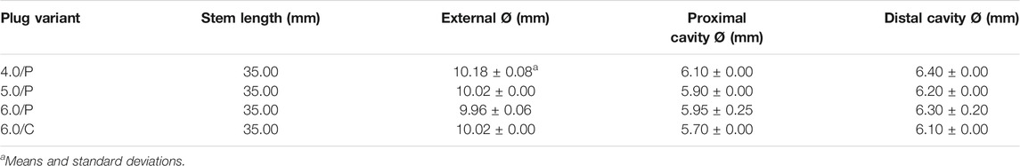
TABLE 2. SolidWorks-designed tibiae plug variants dimensions for 9 mm diameter tibiae.
For the radii plug, designed variants had slight dimension changes (Table 3). It is noteworthy that the stem length had small deviations in radii plugs, which were especially marked at the 8.1/6 variant.
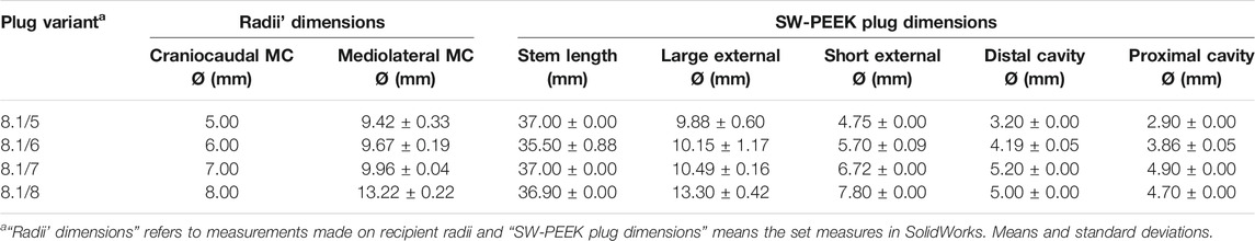
TABLE 3. SolidWorks-designed radii plug variants dimensions and radii medullary cavity (MC) diameters where variants were inserted.
Before printing the endoprosthesis’ plugs with PEEK, we delimited the proper nozzle and print-bed temperature for printing a 30 mm3 × 30 mm3 × 1.5 mm3 cube in a FunMat HT printer.
The qualitative quality criteria were assessed and correlated with the nozzle and print-bed temperatures. Table 4 shows the correlation coefficients and the corresponding p values in parentheses among parameters. The best printing results were achieved with 400–410°C nozzle and 130°C bed temperatures. During these tests, the hardened steel nozzle turned out to be the better option for increasing surface quality.
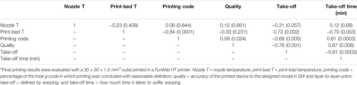
TABLE 4. Pearson’s correlation among thermal parameters and final printing resultsa.
The Pearson correlation showed significant positive correlation among the printing code, quality, and take-off time. However, significant inverse correlations were recorded between the printing code or quality and take-off. In addition, print-bed temperature was inversely related with the printing code and take-off time and negatively with take-off.
Different parameters were modified for the three printing orientations, to decide the best position for printing the devices (Table 5). The best print quality of the PEEK plug was obtained in H-orientation, although it showed the lowest extruder multiplier and the distance between models. No significant differences were recorded among the printing orientation regarding default speed, the printing code, or take-off means.
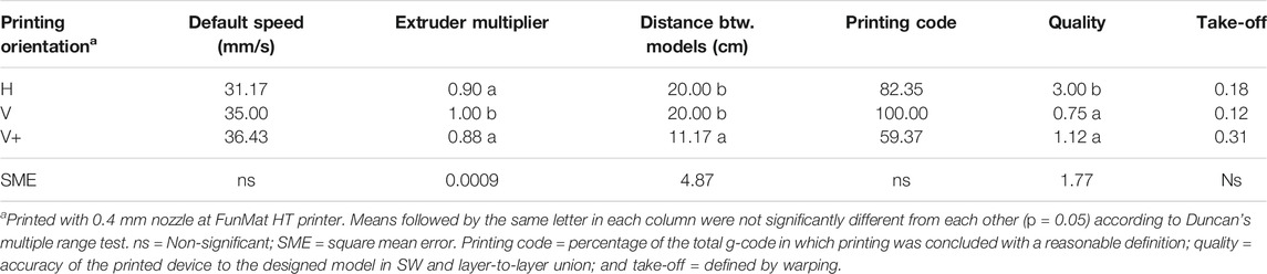
TABLE 5. PEEK printing parameters and results of the tibiae plug printed at different orientations.
Furthermore, the circular “umbrella” variant was well printed in vertical orientations but showed defects in the sharpness of the edge closed to print-bed in the H-orientation. The hexagonal “umbrella” variant was printed without problems and had good quality in the H-orientation.
As a result of the previous sections, only horizontally printed tibiae plugs were inserted in bones. The best bone anchorage and thread strength of endoprosthesis were recorded by 6.0/C and 6.0/P, respectively, followed by 5.0/P (Table 6). Nevertheless, 4.0/P variants could not even be inserted into the bone. As SW-designed external and proximal cavity Ø were reduced, differences with 3D-printed dimensions increased. Distal cavity Ø difference was negligible at 6.0 variants. Stem length differences were quite variable between variants despite the same SW-designed stem length. Maximum cooling percentage was recorded for 4.0/P variants.
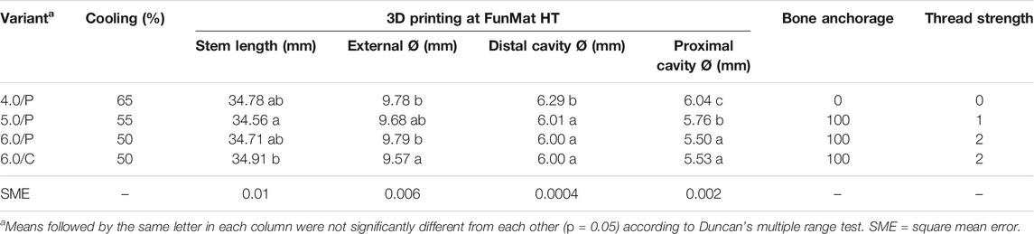
TABLE 6. 3D-printed (FunMat) tibiae PEEK-plug dimensions and their corresponding bone anchorage and thread strength values.
All 3D-printed dimensions were similar to SW-designed dimensions. The differences between the printed dimensions and the original designed ones were quite constant without significant variation at each plug variant (Table 7). These differences of dimension were used for readjusting the PEEK plug dimensions in SW to enhance bone fitting.
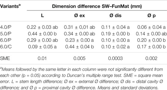
TABLE 7. Designed (SW) and printed (FunMat) dimensions differences of the tibiae endoprosthesis’ PEEK plug.
Real dimensions of forelimb endoprostheses were measured (Table 8) and compared with Table 2 data (Table 9). All variants had the same value of the cooling parameter except 8.1/6, whose cooling parameter varied from 20 to 50% as described in Table 10. Only the 8.1/6 variant showed positive bone anchorage and thread strength.
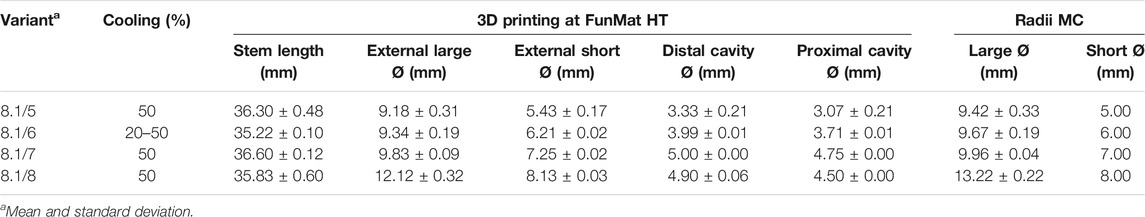
TABLE 8. 3D-printed (FunMat) radii PEEK plug variants and radii medullary cavity (MC) dimensions, and different cooling values.
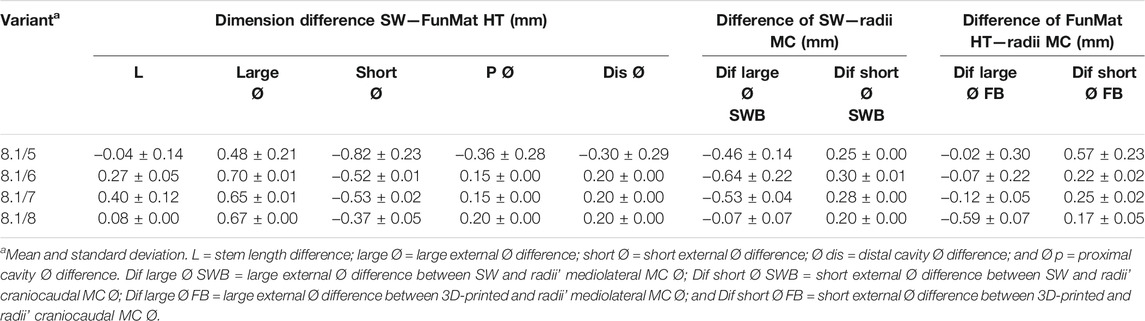
TABLE 9. Dimension differences between designed (SW), 3D-printed (FunMat HT and F) radii PEEK plugs and radii medullary cavity (MC).
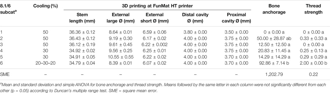
TABLE 10. 3D-printed (FunMat) dimensions and their corresponding bone anchorage and thread strength values for all 8.1/6 subcategories (8.1/6 Subcat).
Standard deviation of all variants was kept close to 0 at all parameters, except for 8.1/5 variant where deviation was greater for all parameters. These trends were similar for all parameters and variants for “dimension difference SW–FunMat” (Table 9). These dimension differences were used for readjusting PEEK plug dimensions in SW for enhancing bone fitting.
Bone anchorage and thread strength were significantly different in the 8.1/6-6 subcategory (Table 10), whose thread strength had a value equal to 2. Thread strength was only evaluated after achieving proper long and short external Ø, meaning adequate bone anchorage only considering the press-fit factor. No huge differences of standard deviation were obtained among the 8.1/6 subcategories and inside each group. The 8.1/6-6 subcategory was the only one where the cooling parameter was varied during printing.
An analysis of the relation between dimension differences—3D printed, SW, and bone—of 8.1/6 variants and bone anchorage was carried out using PCA. The bone anchorage was related with the “external large Ø difference between SW and the bone,” “external short Ø difference between SW and the bone,” “proximal cavity Ø difference between SW and FunMat,” and “distal cavity Ø difference between SW and FunMat” (Figure 4). The first three components accounted for 44.14, 22.35, and 20.00% of the total variation, respectively.
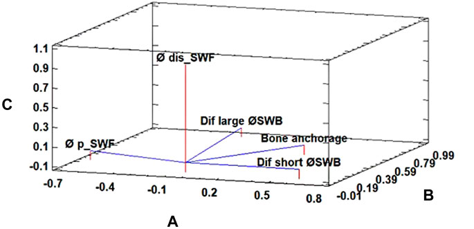
FIGURE 4. Principal component analysis for the bone anchorage parameter of 8.1/6 subcategories of the radii’ PEEK plug. The first three components accounted for 44.14% (A), 22.35% (B), and 20.00% (C) of the total variation, respectively. Where “Dif large Ø SWB” is external large Ø difference between the SolidWorks-designed plug (SW) and the bone, “Dif short Ø SWB” is external short Ø difference between SW and the bone, “Øp_SWF” proximal cavity Ø difference between SW and FunMat, and “Ødis_SWF” is distal cavity Ø difference between SW and FunMat.
Another PCA was carried out with 8.1/6 variants, which confirmed that thread strength was related to “distal cavity Ø in SW,” “proximal cavity Ø in SW,” “proximal cavity Ø difference between SW and FunMat,” and “distal cavity Ø difference between SW and FunMat” (Figure 5). The first three components accounted for 51.52, 23.16, and 20.00% of the total variation, respectively.
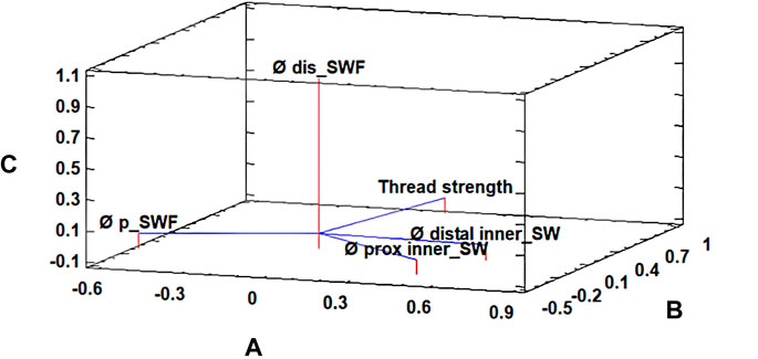
FIGURE 5. Principal component analysis for the thread strength parameter of 8.1/6 subcategories of the radii’ PEEK plug. The first three components accounted for 51.52% (A), 23.16% (B), and 20.00% (C) of the total variation, respectively. Where “Ø distal inner_SW” is distal cavity Ø in SolidWorks (SW), “Ø prox inner_SW” is proximal cavity Ø in SW, “Ø p_SWF” is proximal cavity Ø difference between SW and FunMat, and “Ø dis_SWF” is distal cavity Ø difference between SW and FunMat.
With these data, as presented in Table 3 and Table 10, it was possible to carry out simple regression between SW-designed and radii MC diameters (Eqs 1, 2) with those models whose bone anchorage was 100.
Equation 1. Simple correlation of large Ø between SW (Large ØSW) and radii MC (Large ØMC) (R2 = 0.99; r = 0.99; p = 0.00).
Equation 2. Simple correlation of short Ø between SW (Short ØSW) and radii medullary cavity (Short ØMC) (R2 = 0.99; r = 0.99; p = 0.00).
Likewise, two multiple regressions among the SW data, 3D-printed dimensions, and radii MC diameters (Eqs 3, 4):
Equation 3. Short Ø dimension correlation among SW (Short ØSW), 3D-printed (Short ØF), and radii MC (Short ØMC) (R2Adjusted = 0.99; p = 0.0000).
Equation 4. Large Ø dimension correlation among SW (Large ØSW), 3D-printed (Large ØF), and radii MC (Large ØMC) (R2Adjusted = 0.99; p = 0.0000).
Endoprostheses for canine extremities were designed and manufactured in PEEK by FFF technology with different dimensions, before testing their stability and capability of anchorage into the corresponding bones. To the best of our knowledge, this is the first report describing the use of FFF technology and PEEK for manufacturing the internal part of a canine exo-endoprosthesis, and later successfully inserted in radius and tibia bones. Differences in the plug’s external and inner Ø were thoroughly modified and measured for each plug variant. These changes were made to fit the endoprostheses to the distal tibiae or radii MCs without fissuring the cortical bone or hard tightening of threaded rod insertion. Changes in dimensions of plugs’ inner cavity Ø were made to adapt the torque of the threaded rod insertion in the PEEK endoprostheses.
Bone anchorage and thread strength of tibiae PEEK plug variants depended on the proximal and distal cavity Ø, and on the external Ø. The 6.0 tibial variant had the best bone anchorage, probably because it has external Ø close to drilled bone’s MC Ø (9 mm) than the other tibiae PEEK plug variants. The external Ø affects the bone anchorage because of the press-fit mechanism (Pitkin, 2013; Thesleff et al., 2018), which directly depends on the tibiae’ MC and the PEEK plug external diameters. Thread strength depended on the proximal cavity Ø, which means that reduction at the proximal cavity obviously affects how the threaded rod is inserted. The proximal cavity Ø was also related to bone anchorage because, theoretically, the smaller this diameter is, the more radial expansion would be suffered by the PEEK plug while the threaded rod is inserting. These results reveal that the bone anchorage of this device not only depends on the diameter differences between the MC (Drygas et al., 2008; Fitzpatrick et al., 2011; Li and Brånemark, 2017) and the PEEK plug external Ø but also is affected by a mild radial compression into cortical bone caused by the insertion of threaded rod inside the PEEK plug. This compression made an extra mechanical anchorage, thanks to a mild deformation of the PEEK plug, which could adapt its shape to the medullary cavity better than metal devices.
On the other hand, radii PEEK plug variants depended mainly on the radii craniocaudal MC diameter, which had slight dimension changes. Variations of the large external Ø in each variant depend on a huge variability of the radii mediolateral MC diameter. Due to these remarkable differences in the diameters of the canine radii (Brianza et al., 2006), our section plane of the radii plug stem had an elliptic shape. In comparison with other forelimb prostheses, the transversal section of the stem is usually circular in transradial devices, for example, in the iTAP (Fitzpatrick et al., 2011) and OPRA (Jönsson et al., 2011) devices. An elliptical section has only been indirectly described by DeVasConCellos et al. (2012) in a specific metal-made 3D-printed implant. The elliptical shape offers an inherently better torque strength of the device inside the bone than a circular one, due to the avoidance of the relative turn which could be observed in a circular shape inside an elliptical one.
Bone anchorage of radii plug variants depends on dimension differences between SW and FunMat, SW, and the bone. These results showed that bone anchorage did not only depend on the press-fit mechanism of the PEEK-plug’s external diameters such as described for other exo-endoprostheses (Drygas et al., 2008; Fitzpatrick et al., 2011; Jönsson et al., 2011). Bone anchorage was also affected by a mild radial compression to the cortical bone, such as that which occurred in our tibiae endoprostheses. In addition, a correlation was achieved between the large and short external diameters of SW-designed, 3D-printed, and radii MC diameters, to fit for future devices. Nevertheless, these equations were obtained for the FunMat HT printer, so probably could not be generally used for other 3D printers on the market.
Plugs with stem’s positive surface were better in withstanding pull-off forces than the negative surface group. This characteristic suggested more stability inside the bone MC and the anchorage capability of positive surfaces, at least in the early post-surgery period. Positive surfaces or the roughness of the surface have been demonstrated as a good solution for the enhancement of bone tissue bonding and osteocompatibility (Qiu et al., 2014; Almasi et al., 2016). Additionally, the natural roughness of 3D-printed surfaces due to the layer deposition could be an excellent characteristic for enhancing bone–tissue bonding. Furthermore, the cavity created between two printed layers could be modified to obtain a cavity height diameter range (250–1,000 µm) proposed by other studies to promote bone ingrowth (Pendegrass et al., 2006; Autefage et al., 2012).
Another interesting result was the very good quality of the hexagonal “umbrella” variant in H-orientation. Hexagonal edges are at 30 in terms of vertical axis of the model during printing, making a perfect solution to save print-time and material (Leary et al., 2014; Fazzini et al., 2019)—since it reduces the number of supports. Morphological similarity to designed surfaces was achieved in PEEK and PLA prototypes, although those in PEEK had higher mechanical characteristics and a less detailed surface than the PLA prototypes. This reduction in surface precision was probably due to printer mechanical precision (Zgórniak and Stachurski, 2010), since PLA and PEEK models were printed on different printers. In addition, PEEK printer precision could also be affected by high chamber temperatures (90°C), which could interfere with different components of the printer—such as its timing belts—affecting their functionality, as well as interfering in PEEK cooling performance (Kurtz, 2019).
As external and proximal cavity Ø in SW were reduced, differences with 3D printing results increased with a constant value. This could mean a decrease in printer precision at reduced dimensions. This could be because any printer has an axis resolution—defined by mechanical aspects—which will affect more and be more decisive in these small, printed volumes (Zgórniak and Stachurski, 2010). In this study, the 8.1/5 radii endoprosthesis variant presented the smallest dimensions and the highest standard deviation, which suggests low repeatability. The difference of the distal cavity Ø of the tibiae plug was almost negligible in the 6.0 tibial endoprosthesis variants. This could mean a minimal error between design and manufacturing dimensions. In addition, stem length differences of tibial endoprostheses were quite variable between variants despite the same SW stem length, which could depend on an error range on the Y axis and/or the cooling parameter (Wu et al., 2014; Yang et al., 2017). Dimension differences between SW-designed and 3D-printed devices were mostly constant in radii and tibiae plugs. This result surely means that differences could be affected by the printer’s mechanical precision and the shrinkage percentage of PEEK during and after fabrication. Furthermore, this constant difference suggests all temperature parameters were maintained during the printing and cooling curve after printing.
Nevertheless, there are some studies (Wu et al., 2014; Arif et al., 2018) that do not use a cooling fan during printing due to mechanical property variations of functional parts. However, we were not able to print our models successfully without turning it on. The cooling parameter was generally quite variable in any endoprosthesis variants, except in the 6.0/C tibiae and 8.1/7 radii variants. However, compared with the tibiae plug, the cooling parameter of radii plugs had been set a large range of values, even in the same variant. Large cooling reductions were set in smallest radii variants to avoid device delamination during bone insertion, which was remarkable in smaller sizes.
Printing orientation for fabricating functional objects must be considered for withstanding the principal strains during the mechanical loads because forces are better stood at the main filament rod direction instead of by layer unions in 3D-printed objects (Arif et al., 2018; Pu et al., 2020). Also, other factors should be considered, such as printing material, printing volume, quality of printed object, printing time, or amount of material used. Our endoprosthesis should withstand two main shear stresses over the largest axis of the model as well transversal compression stress throughout this axis due to the threaded rod insertion and bone. Another force which will be withstood once endoprostheses were inserted in the bone is a flexural strength at the stem-umbrella level. Three different orientations were evaluated: two of them—V and V+—did not differ in layer orientation but they did in print-time, wasted material, and fabrication time for each layer. The best significant quality of the printed plug was obtained by the H-orientation (Table 5). Compared with the other two orientations, H-orientation could withstand low flexural forces applied by the hand and experienced fewer device failures during insertion of the threaded rod where torsional forces were applied. In addition, H-orientation had low take-off values so was easier to print. H-orientation will also be generally expected to withstand applied forces due to its filament rods’ direction. Variations in the extruder multiplier stemmed from an effort to reduce thermal retention of layers in vertical orientations and guaranteeing a proper surface definition. Gordeev et al. (2018) observed extruder multiplier values under 0.9 for different materials affected the porosity of 3D printed objects by FFF/FDM. Therefore, the extruder multiplier must be a parameter to be considered when a functional medical device is fabricated using this technology. In our device, due to its final function and dual ambience—in and outside the body—a certain level of leak tightness will be guaranteed. Furthermore, H orientation and its filament rod continuity for external walls and a smaller number of layers promote this tightness (Arif et al., 2018).
Best quality printing was achieved with 400–410°C nozzle and 130°C bed temperatures, a hardened steel nozzle, and cooling turned on. This successful nozzle and bed temperature agree with the range temperature of other studies (Wu et al., 2014; Yang et al., 2017; Arif et al., 2018; Pu et al., 2020), but this always depends on which 3D printer was used. Print-bed temperature was inversely related with the printing code and take-off time and positively with take-off. These correlations indicate that high bed temperature will ruin the success of the print, the opposite of what happens with larger models, higher bed temperatures will be needed for a proper bed adhesion (Wu et al., 2014; Yang et al., 2017). The highest values of bed temperature immediately ruin these fast and small prints, because the first layer probably cooled down quickly so unequal crystallization occurred, causing high filament tensions (Wu et al., 2014) when the next layer started to be printed.
During our study, different nozzle materials were tried, but different surface qualities have been observed with better preliminary results with the hardened steel nozzle, probably because of the differences in the thermal behavior of each material. As it is well known, brass has the greatest capability for thermal transmission, likewise thermal variations, followed by steel and hardened steel (Incropera et al., 2007). We suggest combining both concepts (surface quality and material thermal transmission) because high and constant nozzle temperature variations were observed during printing at FunMat HT but not at the Titan 300. To the best of our knowledge, no studies have focused on the use of different nozzle materials; however, a thorough study should be made.
3D printing was described in this study as an iterative, affordable, and reasonable option for producing small medical devices using high-performance plastic materials like PEEK. Small PEEK endoprostheses for canine extremities were designed and successfully manufactured by FFF technology for long bones with different sizes. Print parameters for PEEK were adjusted specifically for our small volumes and its suggested real force bearing. The bone anchorage of the designed endoprosthesis depended on press-fit and radial compression mechanisms since the moment the endoprosthesis was inserted into the bone.
The original contributions presented in the study are included in the article/Supplementary Material; further enquiries can be directed to the corresponding author.
This study was approved by the Animal Care and Use Committee of the Veterinary Faculty of Madrid (n° 05/2019, Clinical Veterinary Hospital, the University Complutense of Madrid, Spain).
Conceptualization: RM-D; data curation: RM-D; formal analysis: RM-D; funding acquisition: JR-Q and SP-F; investigation: RM-D and SP-F; methodology: RM-D and SP-F; project administration: JR-Q and SP-F; resources: JR-Q and SP-F; software: SP-F; supervision: JR-Q and SP-F; validation: RM-D; writing—original draft: RM-D; writing—review and editing: RM-D, JR-Q, and SP-F.
This study was supported by the Regional Government of Madrid, Spain (grant IND2017/BMD-7726). R. M received a PhD fellowship from this grant. The Regional Government of Madrid has not involved in any decision about the development of this study.
The authors declare that the research was conducted in the absence of any commercial or financial relationships that could be construed as a potential conflict of interest.
All claims expressed in this article are solely those of the authors and do not necessarily represent those of their affiliated organizations, or those of the publisher, the editors, and the reviewers. Any product that may be evaluated in this article, or claim that may be made by its manufacturer, is not guaranteed or endorsed by the publisher.
We thank Abax Innovation Technologies, and Veterinary Anatomy and Embryology Department of Faculty of Veterinary Medicine at the Complutense University of Madrid for their technical support.
The Supplementary Material for this article can be found online at: https://www.frontiersin.org/articles/10.3389/fmech.2021.693436/full#supplementary-material
Almasi, D., Iqbal, N., Sadeghi, M., Sudin, I., Abdul Kadir, M. R., and Kamarul, T. (2016). Preparation Methods for Improving PEEK's Bioactivity for Orthopedic and Dental Application: A Review. Int. J. Biomater. 2016, 1–12. doi:10.1155/2016/8202653
Arif, M. F., Kumar, S., Varadarajan, K. M., and Cantwell, W. J. (2018). Performance of Biocompatible PEEK Processed by Fused Deposition Additive Manufacturing. Mater. Des. 146 (May), 249–259. doi:10.1016/j.matdes.2018.03.015
Atzeni, E., and Salmi, A. (2012). Economics of Additive Manufacturing for End-Usable Metal Parts. Int. J. Adv. Manuf Technol. 62 (9–12), 1147–1155. doi:10.1007/s00170-011-3878-1
Autefage, A., Palierne, S., Charron, C., and Swider, P. (2012). Effective Mechanical Properties of Diaphyseal Cortical Bone in the Canine Femur. Vet. J. 194 (2), 202–209. doi:10.1016/j.tvjl.2012.04.001
Brånemark, R., Berlin, Ö., Hagberg, K., Bergh, P., Gunterberg, B., and Rydevik, B. (2014). A Novel Osseointegrated Percutaneous Prosthetic System for the Treatment of Patients with Transfemoral Amputation. Bone Jt. J. 96-B (1), 106–113. doi:10.1302/0301-620X.96B1.31905
Brianza, S. Z. M., Delise, M., Maddalena Ferraris, M., D’Amelio, P., and Botti, P. (2006). Cross-Sectional Geometrical Properties of Distal Radius and Ulna in Large, Medium and Toy Breed Dogs. J. Biomech. 39 (2), 302–311. doi:10.1016/j.jbiomech.2004.11.018
Chacón, J. M., Caminero, M. A., García-Plaza, E., and Núñez, P. J. (2017). Additive Manufacturing of PLA Structures Using Fused Deposition Modelling: Effect of Process Parameters on Mechanical Properties and Their Optimal Selection. Mater. Des. 124 (June), 143–157. doi:10.1016/j.matdes.2017.03.065
De Cal, M., María, R., Fernández, S. P., and Rodríguez Quirós, J. (2020). Endoprótesis a medida para huesos largos de animalesOficina Española de Patentes y Marcas ES2736410. Available at: https://patentimages.storage.googleapis.com/0c/f4/54/d74e23ec379b45/ES2736410A1.pdf.
Desrochers, A., St-Jean, G., and Anderson, D. E. (2014). Limb Amputation and Prosthesis. Vet. Clin. North America: Food Anim. Pract. 30 (1), 143–155. doi:10.1016/j.cvfa.2013.11.005
DeVasConCellos, P., Balla, V. K., Bose, S., Fugazzi, R., Dernell, W. S., and Bandyopadhyay, A. (2012). Patient Specific Implants for Amputation Prostheses: Design, Manufacture and Analysis. Vet. Comp. Orthop. Traumatol. 25 (04), 286–296. doi:10.3415/VCOT-11-03-0043
Drygas, K. A., Taylor, R., Hugate, R. R., Sidebotham, C. G., Hugate, R. R., and Mcalexander, H. (2008). Transcutaneous Tibial Implants: A Surgical Procedure for Restoring Ambulation after Amputation of the Distal Aspect of the Tibia in a Dog. Vet. Surg. 37 (4), 322–327. doi:10.1111/j.1532-950X.2008.00384.x
Durham, J. W., Montelongo, S. A., Ong, J. L., Guda, T., Allen, M. J., and Rabiei, A. (2016). Hydroxyapatite Coating on PEEK Implants: Biomechanical and Histological Study in a Rabbit Model. Mater. Sci. Eng. C 68 (November), 723–731. doi:10.1016/j.msec.2016.06.049
Evans, N. T., Torstrick, F. B., Lee, C. S. D., Dupont, K. M., Safranski, D. L., Chang, W. A., et al. (2015). High-Strength, Surface-Porous Polyether-Ether-Ketone for Load-Bearing Orthopedic Implants. Acta Biomater. 13 (February), 159–167. doi:10.1016/j.actbio.2014.11.030
Evans, S. L., and Gregson, P. J. (1998). Composite Technology in Load-Bearing Orthopaedic Implants. Biomaterials 19 (15), 1329–1342. doi:10.1016/S0142-9612(97)00217-2
Farrell, B. J., Prilutsky, B. I., Prilutsky, R. S., Dalton, J. F., and Pitkin, M. (2014). An Animal Model to Evaluate Skin-Implant-Bone Integration and Gait with a Prosthesis Directly Attached to the Residual Limb. Clin. Biomech. 29 (3), 336–349. doi:10.1016/j.clinbiomech.2013.12.014
Fazzini, G., Paolini, P., Paolucci, R., Chiulli, D., Barile, G., Leoni, A., et al. (2019). “Print on Air: FDM 3D Printing without Supports,” in 2019 II Workshop on Metrology for Industry 4.0 and IoT (MetroInd4.0&IoT) (Naples, Italy: IEEE), 350–354. doi:10.1109/METROI4.2019.8792846
Fitzpatrick, N., Smith, T. J., Pendegrass, C. J., Yeadon, R., Ring, M., Goodship, A. E., et al. (2011). Intraosseous Transcutaneous Amputation Prosthesis (ITAP) for Limb Salvage in 4 Dogs. Vet. Surg. 40 (8), 909–925. doi:10.1111/j.1532-950X.2011.00891.x
Galindo-Zamora, V., von Babo, V., Eberle, N., Betz, D., Nolte, I., and Wefstaedt, P. (2016). Kinetic, Kinematic, Magnetic Resonance and Owner Evaluation of Dogs before and after the Amputation of a Hind Limb. BMC Vet. Res. 12 (1), 20. doi:10.1186/s12917-016-0644-5
Golachowski, A., Al Ghabri, M. R., Golachowska, B., Al Abri, H., Lubak, M., and Sujeta, M. (2019). Implantation of an Intraosseous Transcutaneous Amputation Prosthesis Restoring Ambulation after Amputation of the Distal Aspect of the Left Tibia in an Arabian Tahr (Arabitragus Jayakari). Front. Vet. Sci. 6 (June), 182. doi:10.3389/fvets.2019.00182
Gordeev, E. G., Galushko, A. S., and Ananikov, V. P. (2018). Improvement of Quality of 3D Printed Objects by Elimination of Microscopic Structural Defects in Fused Deposition Modeling. PLoS ONE 13 (6), e0198370. doi:10.1371/journal.pone.0198370
Hall, C. W., Cox, P. A., and Mallow, W. A. (1976). Skeletal Extension Development: Criteria for Future Designs. Bull. Prosthet Res., 69–96.
Hoffmeister, B. K., Smith, S. R., Handley, S. M., and Rho, J. Y. (2000). Anisotropy of Young's Modulus of Human Tibial Cortical Bone. Med. Biol. Eng. Comput. 38 (3), 333–338. doi:10.1007/BF02347055
Hopkinson, N., and Dicknes, P. (2003). “Analysis of Rapid Manufacturing-Using Layer Manufacturing Processes for Production,” in Proceedings of the Institution of Mechanical Engineers, Part C: Journal of Mechanical Engineering Science 217 (1), 31–39. doi:10.1243/095440603762554596
Incropera, F. P., Dewitt, D. P., Bergman, T. L., and Lavine, A. (2007). Fundamentals of Heat and Mass Transfer. 6th ed., Vol. 1. Hoboken, NJ: John Wiley & Sons.
Jönsson, S., Caine-Winterberger, K., and Brånemark, R. (2011). Osseointegration Amputation Prostheses on the Upper Limbs. Prosthetics Orthotics Int. 35 (2), 190–200. doi:10.1177/0309364611409003
Keller, T. S., Mao, Z., and Spengler, D. M. (1990). Young's Modulus, Bending Strength, and Tissue Physical Properties of Human Compact Bone. J. Orthop. Res. 8 (4), 592–603. doi:10.1002/jor.1100080416
Koëter, S., van Loon, C. J. M., and van Susante, J. L. C. (2006). Lateral Femoral Condyle Osteochondral Fracture Caused by a Patella Luxation: Advantages and Disadvantages of PLA Fixation. Eur. J. Orthop. Surg. Traumatol. 16 (3), 268–270. doi:10.1007/s00590-005-0053-0
Kurtz, S. M. (2019). in PEEK Biomaterials Handbook. 2nd ed (Elsevier), 1. doi:10.1016/C2016-0-02479-8
Kurtz, S. M., and Devine, J. N. (2007). PEEK Biomaterials in Trauma, Orthopedic, and Spinal Implants. Biomaterials 28 (32), 4845–4869. doi:10.1016/j.biomaterials.2007.07.013
Lathers, S., and La Belle, J. (2016). Advanced Manufactured Fused Filament Fabrication 3D Printed Osseointegrated Prosthesis for a Transhumeral Amputation Using Taulman 680 FDA. 3D Printing and Additive Manufacturing 3 (3), 166–174. doi:10.1089/3dp.2016.0010
Leary, M., Merli, L., Torti, F., Mazur, M., and Brandt, M. (2014). Optimal Topology for Additive Manufacture: A Method for Enabling Additive Manufacture of Support-free Optimal Structures. Mater. Des. 63 (November), 678–690. doi:10.1016/j.matdes.2014.06.015
Li, Y., and Brånemark, R. (2017). Osseointegrated Prostheses for Rehabilitation Following Amputation. Unfallchirurg 120 (4), 285–292. doi:10.1007/s00113-017-0331-4
Ligon, S. C., Liska, R., Stampfl, J., Gurr, M., and Mülhaupt, R. (2017). Polymers for 3D Printing and Customized Additive Manufacturing. Chem. Rev. 117 (15), 10212–10290. doi:10.1021/acs.chemrev.7b00074
Mich, P. M. (2014). The Emerging Role of Veterinary Orthotics and Prosthetics (V-OP) in Small Animal Rehabilitation and Pain Management. Top. Companion Anim. Med. 29 (1), 10–19. doi:10.1053/j.tcam.2014.04.002
Niinomi, M. (1998). Mechanical Properties of Biomedical Titanium Alloys. Mater. Sci. Eng. A 243 (1–2), 231–236. doi:10.1016/S0921-5093(97)00806-X
Panayotov, I. V., Orti, V., Cuisinier, F., Yachouh, J., and Yachouh, J. (2016). Polyetheretherketone (PEEK) for Medical Applications. J. Mater. Sci. Mater. Med. 27 (7), 118. doi:10.1007/s10856-016-5731-4
Pendegrass, C. J., Goodship, A. E., and Blunn, G. W. (2006). Development of a Soft Tissue Seal Around Bone-Anchored Transcutaneous Amputation Prostheses. Biomaterials 27 (23), 4183–4191. doi:10.1016/j.biomaterials.2006.03.041
Phillips, A., Kulendra, E., Bishop, E., Monk, M., Parsons, K., and House, A. (2017). Clinical Outcome and Complications of Thoracic and Pelvic Limb Stump and Socket Prostheses. Vet. Comp. Orthop. Traumatol. 30, 265–271. doi:10.3415/VCOT-16-09-0127
Pitkin, M. (2013). Design Features of Implants for Direct Skeletal Attachment of Limb Prostheses. J. Biomed. Mater. Res. 101 (11), a–n. doi:10.1002/jbm.a.34606
Pu, J., McIlroy, C., Jones, A., and Ashcroft, I. (2021). Understanding Mechanical Properties in Fused Filament Fabrication of Polyether Ether Ketone. Additive Manufacturing 37, 101673. doi:10.1016/j.addma.2020.101673
Qiu, Z.-Y., Chen, C., Wang, X.-M., and Lee, I.-S. (2014). Advances in the Surface Modification Techniques of Bone-Related Implants for Last 10 Years. Regenerative Biomater. 1 (1), 67–79. doi:10.1093/rb/rbu007
Ramakrishna, S., Mayer, J., Wintermantel, E., and Leong, K. W. (2001). Biomedical Applications of Polymer-Composite Materials: A Review. Composites Sci. Techn. 61 (9), 1189–1224. doi:10.1016/S0266-3538(00)00241-4
Reilly, D. T., Burstein, A. H., and Frankel, V. H. (1974). The Elastic Modulus for Bone. J. Biomech. 7 (3), 271–275. doi:10.1016/0021-9290(74)90018-9
Ruiz Marín, M., San Hipólito Marín, L., Belarra Arenas, C., Martín Gómez, F., and Martínez-González, J. M. (2009). Synthetic Grafts Materials. Polylactide and Poliglycolide Acid Effects in Bone Regeneration. Avances en Periodoncias 21 (1), 45–52.
Saha, S., Martin, D. L., and Phillips, A. (1977). Elastic and Strength Properties of Canine Long Bones. Med. Biol. Eng. Comput. 15 (1), 72–74. doi:10.1007/BF02441578
Salentijn, G. I., Oomen, P. E., Grajewski, M., and Verpoorte, E. (2017). Fused Deposition Modeling 3D Printing for (Bio)Analytical Device Fabrication: Procedures, Materials, and Applications. Anal. Chem. 89 (13), 7053–7061. doi:10.1021/acs.analchem.7b00828
Séguin, B., and Weigel, J. P. (2012). “Amputations,” in Veterinary Surgery Small Animal. Editors K M. Tobias, and S A. Johnston (Canadá: Elsevier Saunders), 1, 1029–1036.
Snedecor, , George, W., and Cochran, W. G. (1980). Statistical Methods. 7th ed. Ames, Iowa: The State University Press.
Thesleff, A., Brånemark, R., Håkansson, B., and Ortiz-Catalan, M. (2018). Biomechanical Characterisation of Bone-Anchored Implant Systems for Amputation Limb Prostheses: A Systematic Review. Ann. Biomed. Eng. 46 (3), 377–391. doi:10.1007/s10439-017-1976-4
Wendland, T. M., Seguin, B., and Duerr, F. M. (2019). Retrospective Multi-Center Analysis of Canine Socket Prostheses for Partial Limbs. Front. Vet. Sci. 6 (April), 100. doi:10.3389/fvets.2019.00100
Worth, A., Crosse, K., and Kersley, A. (2019). Computer-Assisted Surgery Using 3D Printed Saw Guides for Acute Correction of Antebrachial Angular Limb Deformities in Dogs. Vet. Comp. Orthop. Traumatol. 32 (03), 241–249. doi:10.1055/s-0039-1678701
Wu, W. Z., Geng, P., Zhao, J., Zhang, Y., Rosen, D. W., and Zhang, H. B. (2014). Manufacture and Thermal Deformation Analysis of Semicrystalline Polymer Polyether Ether Ketone by 3D Printing. Mater. Res. Innov. 18 (Suppl. 5), S5-12–S5-16. doi:10.1179/1432891714Z.000000000898
Yang, C., Tian, X., Li, D., Cao, Y., Zhao, F., and Shi, C. (2017). Influence of Thermal Processing Conditions in 3D Printing on the Crystallinity and Mechanical Properties of PEEK Material. J. Mater. Process. Techn. 248 (October), 1–7. doi:10.1016/j.jmatprotec.2017.04.027
Yu, S., Hariram, K. P., Kumar, R., Cheang, P., and Aik, K. K. (2005). In Vitro Apatite Formation and its Growth Kinetics on Hydroxyapatite/Polyetheretherketone Biocomposites. Biomaterials 26 (15), 2343–2352. doi:10.1016/j.biomaterials.2004.07.028
Zgórniak, P., and Stachurski, W. (2010). Determination of Systematic Errors of 3d Printer in Order to Ensure Manufacturing Correctness of the Prototype. Adv. Manufacturing Sci. Techn. 34 (4), 11.
Zhang, J., Wei, W., Yang, L., Pan, Y., Wang, X., Wang, T., et al. (2018). Stimulation of Cell Responses and Bone Ingrowth into Macro-Microporous Implants of Nano-Bioglass/Polyetheretherketone Composite and Enhanced Antibacterial Activity by Release of Hinokitiol. Colloids Surf. B: Biointerfaces 164 (April), 347–357. doi:10.1016/j.colsurfb.2018.01.058
Keywords: patient-specific implant, FDM, bone anchorage, ex vivo, radius, tibia, polyether ether ketone
Citation: Mendaza-DeCal R, Peso-Fernandez S and Rodriguez-Quiros J (2021) Test of Designing and Manufacturing a Polyether Ether Ketone Endoprosthesis for Canine Extremities by 3D Printing. Front. Mech. Eng 7:693436. doi: 10.3389/fmech.2021.693436
Received: 10 April 2021; Accepted: 19 July 2021;
Published: 26 August 2021.
Edited by:
Sofia Scataglini, University of Antwerp, BelgiumReviewed by:
Jingchao Jiang, The University of Auckland, New ZealandCopyright © 2021 Mendaza-DeCal, Peso-Fernandez and Rodriguez-Quiros. This is an open-access article distributed under the terms of the Creative Commons Attribution License (CC BY). The use, distribution or reproduction in other forums is permitted, provided the original author(s) and the copyright owner(s) are credited and that the original publication in this journal is cited, in accordance with accepted academic practice. No use, distribution or reproduction is permitted which does not comply with these terms.
*Correspondence: Rosa Mendaza-DeCal, cm1lbmRhemFAdWNtLmVz
Disclaimer: All claims expressed in this article are solely those of the authors and do not necessarily represent those of their affiliated organizations, or those of the publisher, the editors and the reviewers. Any product that may be evaluated in this article or claim that may be made by its manufacturer is not guaranteed or endorsed by the publisher.
Research integrity at Frontiers
Learn more about the work of our research integrity team to safeguard the quality of each article we publish.