 Junyi Wang
 Jiaming Hu
 Yun Chen
94% of researchers rate our articles as excellent or good
Learn more about the work of our research integrity team to safeguard the quality of each article we publish.
Find out more
ORIGINAL RESEARCH article
Front. Mech. Eng., 13 May 2021
Sec. Micro- and Nanoelectromechanical Systems
Volume 7 - 2021 | https://doi.org/10.3389/fmech.2021.679656
This article is part of the Research TopicDevelopments in Acoustic, Phononic, and Mechanical Materials for Wave ControlView all 8 articles
Underwater acoustic wave absorption and control play an important role in underwater applications. Various types of underwater acoustic metamaterials have been proposed in recent years with the vigorous development of acoustic metamaterials. Compared with airborne sound, underwater sound waves have a longer wavelength and much smaller propagation loss, making them more difficult to control. In addition, given that the acoustic impedance of water is much greater than that of air, numerous conventional materials and structures are not suited to underwater use. In this paper, we propose a composite structure based on an excellent broadband low-frequency sound absorber of air using aluminum mixed with rubber. Our composite structure possesses broadband low-frequency (<1,000 Hz) sound absorption underwater, omnidirectional high sound absorption coefficient under the oblique incidence (0–75°), and pressure resistance. It has promising applications for underwater acoustic wave control and contributes to the design of underwater acoustic metamaterials.
Acoustic performance, especially acoustic wave absorption and control, is of great importance for underwater applications such as underwater acoustic communication, underwater acoustic detection, and underwater vehicle coating (Zhu and Huang, 2012; Spence and Fischer, 2016; Sohrabi and Ketabdari, 2020). Many materials have been tested for application in underwater sound absorption, including metal, rubber, plastic, and foam (Wang, 1983), for the broad interest and research attraction on the underwater materials design. To enhance the acoustic energy absorption on the surface of a structure, underwater acoustic materials for sound absorption are usually composed of rubber, polyurethane, or other polymer materials (Roland, 2004). However, traditional underwater acoustic materials suffer from low low-frequency sound waves control, large volume with massive weight, and weak pressure resistance. In the airborne field, a variety of sound absorption structures such as Helmholtz resonators (Li et al., 2018; Huang et al., 2019) and Fabry–Pérot resonators (Long et al., 2019; Kumar and Lee, 2020; Liu et al., 2020), have shown the capability of perfect and broadband absorption. The emergence of acoustic metamaterials shows a new method for broadband sound absorption (Wang et al., 2019, 2020, 2021). Many other metamaterials broadband low-frequency absorbers have been proposed and researched (Mei et al., 2012; Yang et al., 2017; Huang et al., 2020). Nonetheless, many of them with high moduli and loss factors exacerbate their acoustic impedance mismatch with water, blocking efficient absorption, whereas a material with a low modulus such as rubber undergoes deformation to a large extent, which threatens the structural stability in complex underwater environments (Wang et al., 2017).
Micro-perforated panels (MPPs) proposed by Maa (1975) combined with partitioned cavities to form sandwich panels is a popular design in low-frequency sound absorption (Pan et al., 2005). The characteristic acoustic impedance of water is close to the acoustic impedance of common engineering structural materials; in particular, the thinner the micro-perforated panel, the more notable the structural-acoustic coupling between the MPPs and the water. Wang Zefeng et al. discussed the potential of the micro-perforated structure in underwater applications and studied the vertical incidence sound absorption coefficient in the water (Wang et al., 2008; Wang and Hu, 2009). From their result, MPPs can be designed to possess a better underwater sound absorption when castor oil fills the cavities for impedance matching compared to MPPs in air. Without castor oil, the flexible MPPs can make up the mismatching impedance; a flexible backing panel can increase its low-frequency maximum absorption coefficient (Hou et al., 2021).
On the other hand, the partitioned cavities known as a honeycomb structure can yield broadband sound absorption at a deep subwavelength thickness (Peng et al., 2018). Han et al. created a honeycomb-corrugation hybrid sandwich core as a promising structure for ultra-lightweight load-bearing and energy-absorption applications (Han et al., 2016). Tang et al. proposed that sub-millimeter perforations added on the panels and corrugations would negligibly influence the rigidity of perforated honeycomb-corrugation hybrid (PHCH) sandwich panels but enhance the broadband low-frequency sound absorption of PHCH (Tang et al., 2017). The current research on honeycomb structures is mainly focused on air environments, and most only care about the vertical incident plane wave. There have been very few studies on underwater perforated honeycomb structures and oblique incidence conditions.
In this paper, we conducted a study on a PHCH structure regarding its underwater low-frequency sound absorption performance. We will demonstrate our novel composite PHCH structure by replacing the rigid materials of the top and bottom panels and corrugation with the flexible material, namely rubber. Our composite PHCH was simulated underwater and under oblique incidence conditions with the finite element method (FEM) at <1,000 Hz. The rubber with a low modulus contributes elasticity and damping to the structure, making it capable of efficient underwater low-frequency sound absorption. The oblique wave incidence boosts the energy dissipation, leading to an increase in the average absorption coefficient. Our composite PHCH structure also retains the bending stiffness of rigid PHCH to the same degree. It manifests bright prospects as a lightweight, pressure-resistant, and omnidirectional underwater low-frequency absorber.
The geometric model is built using COMSOL Multiphysics 5.6. As shown in Figure 1, the PHCH consists of two panels, rectangular cavities, and corrugation plates. The top panel is perforated with micro-holes as MPPs, while the bottom panel is a sealed backing panel for sound reflection. The micro-holes are cylindrical and distributed above every cavity in the center, so the water from above the MPPs can fill in the cavities through the micro-holes. The corrugation plates are inclined to an angle of θ° as shown in Figure 2B. In addition, there are micro-holes perforated in the corrugation plates. The vertical location of the micro-holes is the same as where the MPPs are perforated. Some parts of the corrugation plates are horizontal, among which the upper are perforated while the lower are not. Figure 2 shows 2D views. The rectangular cavities are formed by multiple cells with the outer side length of b2 and inner side length of b1, as shown in Figure 2A. Between the outer cells and inner cavities are partition boards of thickness tp = b2 − b1. The micro-hole can be seen in the center of the cavities with diameter d1. The angle of inclination is given by
Figure 1. The geometry of the underwater PHCH structure.
Figure 2. (A) Top view of one single cell of a rectangular cavity; (B) Front perspective view of two panels and corrugation plates.
In addition, as shown in Figure 2B, the thickness of MPPs and bottom panels are both t1 while the thickness of the corrugation plates is t2, the micro-holes in the corrugation plates have diameter d2, and the height of rectangular cavities is H. Table 1 lists the chosen values for each parameter in our structure.
Table 1. Geometric parameters of the structure.
The whole PHCH shown in Figure 1 is a periodical arrangement of six-unit cells as shown in Figure 3. Studying the performance of the entire PHCH can be replaced by studying the performance of these six-unit cells. Figure 3B shows the front view of six-unit cells partitioned by vertical boards and crossed by corrugation plates. From left to right, the six cavities are labeled C1 − C6 as shown in Figure 3C. C1 and C4 are both H′ = H − t2 in height. C2 and C3 are symmetric with C5 and C6 relative to C4. Based on the model shown in Figure 3, we tested our composite structure's acoustic and mechanical performance.
Figure 3. (A) Six cavities periodically forming the whole structure; (B) Front perspective view of six-unit cells; (C) Details of the 2-D modal.
The composite structure consists of two materials, aluminum and rubber, whose properties' parameters are listed in Table 2. The green and orange parts in Figure 3C are set as rubber, while the partition boards are aluminum. The white area in the cavities and holes is filled with water to simulate an underwater environment.
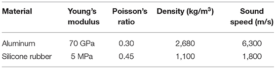
Table 2. Basic materials' parameters including Young's modulus, Poisson's ratio, density, and sound speed in the material.
First, we consider an all-aluminum structure and only analyze the first four cells for simplicity. As shown in Figure 4, the inclined corrugation plates are replaced by the equivalent horizontal plates in C2 and C3, whose height is shortened by . Keeping the same volume for the cavities, the upper cavity height D1 and lower cavity height D2 are calculated as
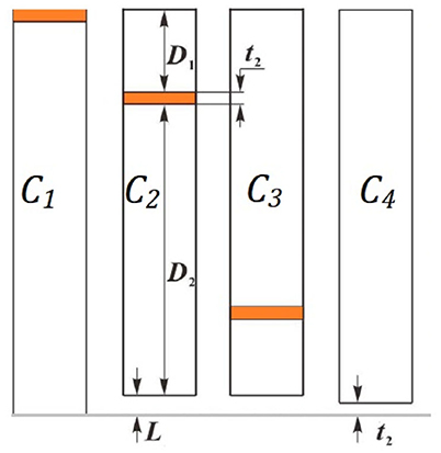
Figure 4. The equivalent simplified four cells.
The upper cavity height C3 equals the lower cavity height C2 and vice versa. Thus, all six-unit cells can be analyzed separately and then be parallelly connected. Each cell can be considered a serial connection of an MPP and one or two layers of water cavity.
The sound absorption coefficient analysis is based on the acoustic impedance analysis in equivalent circuits. The calculation of the acoustic impedance begins with the lower cavity and then the upper cavity, whose acoustic impedance is given by
where j is the imaginary unit, k is the wavenumber, and Z0 is the characteristic impedance of water. Zc is serially connected to the equivalent perforated plate colored orange in Figure 4. The acoustic impedance of the perforated plate is calculated using the same equation as MPPs given by,
where ρ0, ω, and μ are the density of water, the angular frequency of sound, and the dynamic viscosity coefficient of the water, respectively. B0,1 is the 0th and 1st order Bessel function of the first kind. t and d are the thickness of the plate and the diameter of the perforation, respectively. y is the perforation constant, . p is the porosity of the plate given by . Ψ is the Fok function,
The acoustic impedance of the lower layer is given by
From the lower layer to the upper layer, the acoustic impedance is transferred and the whole cavity's acoustic impedance is given by
After the connection in serial to ZMPP and then connecting in parallel, the acoustic impedance of the six-unit cells is given by
Therefore, under the norm incident condition, the sound absorption coefficient is
If the incident wave is oblique with angle φ, the sound absorption coefficient will be
where β(φ, k) is introduced out of solid dissipation and equals to 0 under the norm incident condition.
The above analysis is on the all-aluminum structure. If we replace the top and bottom panels and corrugation plate with rubber, the flexibility of the rubber will influence the acoustic impedance and introduce a velocity impedance that is connected in parallel to ZMPP and ZP. Furthermore, the flexible backing panel's velocity impedance is also introduced and connected in parallel to Zlow. As a result, the mismatch between Zt and Z0 can be lessened through the introduction of rubber in the structure.
The FEM is an effective method to study the composite structure's underwater performance. We use COMSOL Multiphysics 5.6 to operating the FEM and run the numerical simulation. As shown in Figure 5, the model has three kinds of materials, water, rubber, and aluminum. The transparency area and the cavities are filled with water. On the top, there is a perfectly matched layer (PML) that absorbs all the acoustic waves reflected from the structure to simulate an infinite semi-space. Right beneath the PML is an incident field with background pressure. The boundary of the incident field is set under the periodic condition to simulate an infinite water area. A pressure acoustic module is applied in the PML and acoustic incident field. The incident directions studied for the acoustic waves are 0°, 30°, 45°, 60°, and 75°.
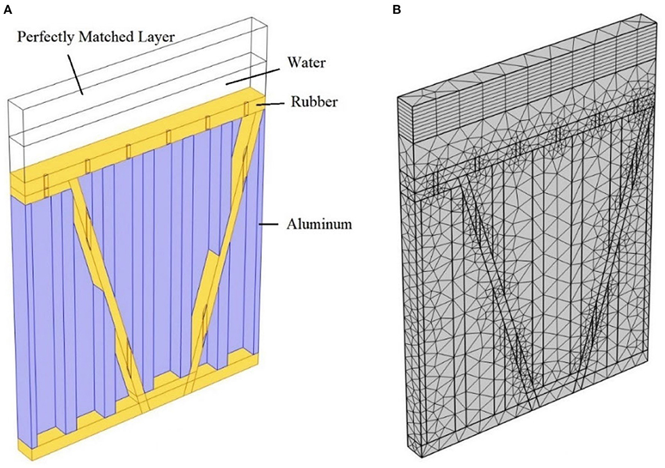
Figure 5. COMSOL model for numerical simulation (A) Line frame of the model and materials settings; (B) Mesh built of the model.
The yellow part in Figure 5A is rubber and the blue part is aluminum, which represents the panels with corrugation plates and partition boards, respectively. The periodic condition is also set on the boundary of the colored parts to simulate the structure's periodic arrangement. The solid mechanics module is applied in the colored part where the loss factor of the rubber is set to 0.4 under the linear elastic material interface. A thermoviscous acoustic module is applied in water in the cavities. To ensure the continuity of acoustic pressure and vibration velocity at the solid–water interface, the acoustic–structure boundaries are set between the water in the incident field and the rubber MPPs. Likewise, thermoviscous acoustic–structure boundaries are set between the water in the cavities and solid structures. The acoustic–thermoviscous acoustic boundaries are set between the incident field and cavities. All these abovementioned boundaries have multi-physics couplings.
The mesh in the regions should be constructed using Swept with at least eight layers. Other regions' meshes are constructed using Free Tetrahedral. The mesh built is shown in Figure 5B.
The sound absorption coefficient is calculated by
where R is the reflecting coefficient and ps and pb are the scattered pressure and background pressure on the boundary between the incident field and the structure. Our study focuses on the <1,000 Hz frequency range.
We ran the study in COMSOL Multiphysics and exported the result data to MATLAB for plot extraction. Figure 6 shows the theoretical and simulated sound absorption coefficient of the all-aluminum PHCH structure under normal incident condition. The theoretical model conforms well with the simulated model, indicating the rightness of our study results.
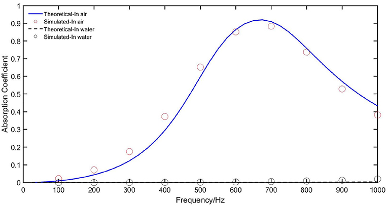
Figure 6. Sound absorption coefficient of the all-aluminum structure in air and water.
Compared with the sound absorption coefficient in air, the sound absorption coefficient in water is nearly zero throughout the entire studied frequency range. This is caused by the difference between the characteristic impedance of air and water. The latter is about 3,600 times the former, so the structure with perfectly matched acoustic impedance to air absorbs little sound when applied in water. Nevertheless, the structure shows low-frequency absorption peaks at about 650 Hz with a broad absorption band (coefficient >0.5) of about 450 Hz. Thus, it is a decent low-frequency sound absorber structure.
Figure 7 shows the underwater sound absorption coefficient under normal incident condition when part of the aluminum is replaced with rubber. The frequency of the new main absorption peak is about 500 Hz with an absorption band of about 775 Hz. Clearly, the structure possesses the property of broadband low-frequency sound absorption without modification in the geometry. The vibration of the perforated rubber plates contributes significantly to the low-frequency sound absorption, so the mismatch in the acoustic impedance is greatly lessened. The rubber backing panel also improves the sound absorption by energy dissipation. The energy dissipation distribution at 500 Hz is shown in Figure 8. There is little difference in the energy dissipation in the cavity, which nearly equals zero, but the energy dissipation is highly enhanced in the perforations and rubber plates. In this way, the composite absorbs more acoustic energy, increasing the sound absorption coefficient.
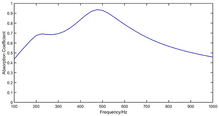
Figure 7. Sound absorption coefficient of the composite structure underwater.
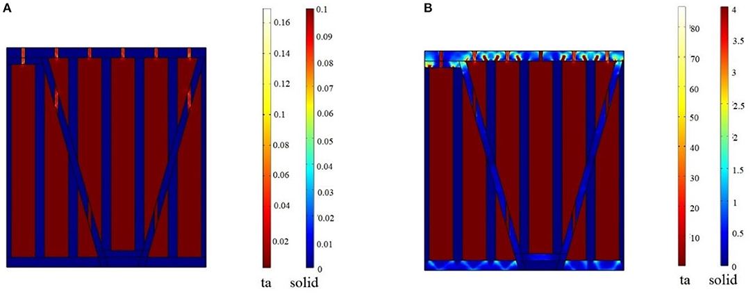
Figure 8. Energy dissipation distribution at 500 Hz. (A) All-aluminum structure; (B) Composite structure. ta and solid stand for thermoviscous acoustics area and solid mechanics area. The unit is W/m3.
The underwater acoustic field is not full of normal incident waves, so it is essential to investigate oblique incident conditions. The multipath effect has been the most notable effect in the underwater environment, so the oblique incident waves are ubiquitous. To study oblique incident sound waves, we change the background wave's incident direction and absorption spectrum as shown in Figure 9. As the oblique angle increases, the transverse component of the incident wave also increases, leading to the shear deformation of the rubber plates. The absorption coefficient at below the first peak—about 200 Hz—increases as the angle increases. The coefficient at >300 Hz deceases, including the amplitude at the main peak (about 500 Hz). Since the loss factor of the transverse shear deformation of rubber is much greater than that of the longitudinal wave, the total energy dissipation is much greater than that of the normal incidence. This is among the reasons for the difference in the sound absorption coefficient at these different angles.
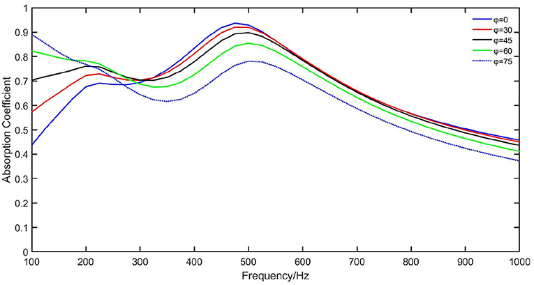
Figure 9. Sound absorption coefficient under oblique incidence.
As the composite structure shows broadband sound absorption at different angles, we consider it a structure capable of omnidirectional sound control. Under the oblique incident condition, the composite structure manifests better low-frequency sound absorption than under the normal incident condition. This property should enable a wide range of applications in water where acoustic waves are usually transmitted multi-directionally.
Rubber is known as a non-resistant material for pressure, while, on the contrary, aluminum is considered a more rigid material. The rubber MPPs applied underwater should have a large capacity for deformation because the water pressure will be much greater than air pressure. Figure 10A shows the deformation of the composite structure under the normal incidence at 500 Hz. The partition boards colored dark blue are aluminum without deformation. The MPPs and backing panels have the greatest deformation among the whole structure. However, the deformations of corrugation plates and backing panels are highly depressed compared to that of MPPs. Since the MPPs and backing panels are much thinner than the height of the partition boards, the deformation in the top and bottom panels has little effect on the integrity and normal form of the whole structure. As a result, the composite structure can be considered resistant to pressure applied by the way of slight deformation in the cavities.
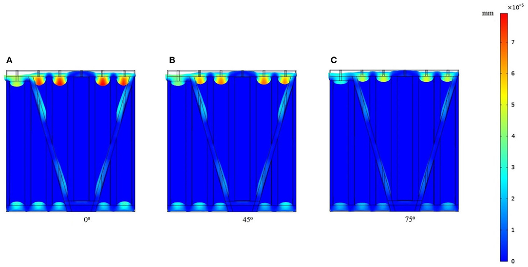
Figure 10. Structural deformation at 500 Hz under the incidence angles as (A) 0°, (B) 45°, and (C) 75°.
The aluminum partition boards support the whole structure from the lateral side and restrict the transverse deformation, which is more harmful to a structure than normal deformation. From Figures 10B,C, when the oblique incident angles increase, the deformations of MPPs and backing panels both decrease in contrast. This decrease in the deformation can also be seen in the average von Mises stress curve shown in Figure 11. The non-deformable partition boards limit MPPs to have a large transverse deformation, which combine with the transverse loss factor of MPPs and contribute to a higher sound absorption coefficient with pressure resistance at low frequencies. Therefore, the composite structure inherits the pressure-resistance property from the PHCH structure and scarifies the deformation in MPPs and backing panels for improved sound absorption performance.
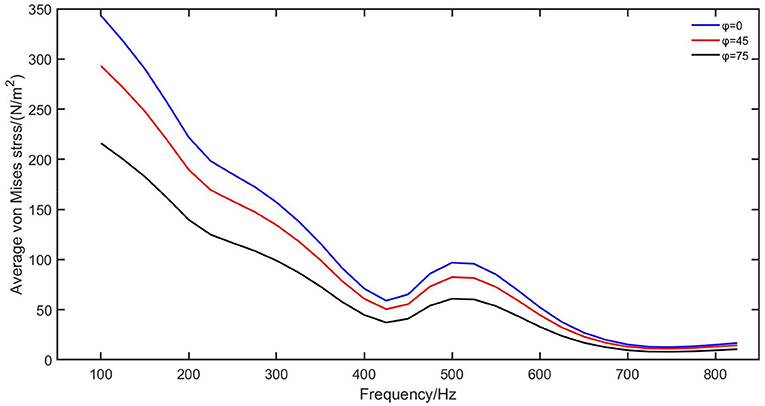
Figure 11. Average von Mises stress of the whole structure under different incident angles at 500 Hz.
In this paper, we propose a novel composite structure consisting of aluminum and rubber to be applied in underwater sound absorption. With its deep sub-wavelength geometry design, the composite structure is supposed to be a lightweight and small-scale absorber. To deal with the mismatch between the acoustic impedance and the characteristic impedance of water, aluminum in the MPPs, backing panels, and corrugation plates in the PHCH structure are replaced by rubber, instead of modifying the geometry, which saves costs in a complex design in terms of the geometric parameters. The composite structure shows a broadband low-frequency sound absorption at the peak at about 500 Hz and an absorption bandwidth of about 775 Hz. Under ubiquitous oblique incident conditions, the composite structure's sound absorption coefficient increases with the angle at the frequency range about <200 Hz, but does not decrease much at the frequency range >300 Hz. The spectrum proves that the composite structure is a proper omnidirectional underwater sound absorber. In the harsh underwater environment, the incident wave from different angles influences the structure's working performance. However, the composite structure is capable of pressure resistance, transverse deformation resistance, and generally good sound absorption under the incidence from different angles. Our research has important implications for underwater acoustic metamaterial design and underwater acoustic wave control.
The original contributions presented in the study are included in the article/supplementary material, further inquiries can be directed to the corresponding author.
YC conceived the idea and advised the research. JW and JH conducted the research and contribute to the manuscript writing. All authors contributed to the article and approved the submitted version.
This work was supported in part by the National Natural Science Foundation of China under Grant 61774049, in part by the National Key R&D Program of China under No. 2019YFE0120700, and in part by the Shanghai Municipal Commission of Economy and Informatization under Grant PKX2020-D10.
The authors declare that the research was conducted in the absence of any commercial or financial relationships that could be construed as a potential conflict of interest.
Han, B., Qin, K., Yu, B., Wang, B., Zhang, Q., and Lu, T. J. (2016). Honeycomb–corrugation hybrid as a novel sandwich core for significantly enhanced compressive performance. Mater. Design 93, 271–282. doi: 10.1016/j.matdes.2015.12.158
Hou, J., Zhu, H., Liao, J., and Yuan, S. (2021). Research on the sound absorption coefficient of underwater elastic micro-perforated sound-absorbing structure. Acta Acust. 46, 135–142. doi: 10.15949/j.cnki.0371-0025.2021.01.014
Huang, S., Fang, X., Wang, X., Assouar, B., Cheng, Q., and Li, Y. (2019). Acoustic perfect absorbers via Helmholtz resonators with embedded apertures. J. Acoust. Soc.Am. 145:254. doi: 10.1121/1.5087128
Huang, S., Zhou, Z., Li, D., Liu, T., Wang, X., Zhu, J., et al. (2020). Compact broadband acoustic sink with coherently coupled weak resonances. Sci. Bull. 65, 373–379. doi: 10.1016/j.scib.2019.11.008
Kumar, S., and Lee, H. P. (2020). Labyrinthine acoustic metastructures enabling broadband sound absorption and ventilation. Appl. Phys. Lett. 116:134103. doi: 10.1063/5.0004520
Li, L.-J., Zheng, B., Zhong, L.-M., Yang, J., Liang, B., and Cheng J.-C. (2018). Broadband compact acoustic absorber with high-efficiency ventilation performance. Appl. Phys. Lett. 113:103501. doi: 10.1063/1.5038184
Liu, C. R., Wu, J. H., Yang, Z., and Ma, F. (2020). Ultra-broadband acoustic absorption of a thin microperforated panel metamaterial with multi-order resonance. Compos. Struct. 246:112366. doi: 10.1016/j.compstruct.2020.112366
Long, H., Shao, C., Liu, C., Cheng, Y., and Liu, X. (2019). Broadband near-perfect absorption of low-frequency sound by subwavelength metasurface. Appl. Phys. Lett. 115:103503. doi: 10.1063/1.5109826
Maa, D.-Y. (1975). Theory and design of microperforated-panel sound-absorbing construction. Sci. Sin. XVIII, 55–71.
Mei, J., Ma, G., Yang, M., Yang, Z., Wen, W., and Sheng P. (2012). Dark acoustic metamaterials as super absorbers for low-frequency sound. Nat. Commun. 3:756. doi: 10.1038/ncomms1758
Pan, J., Guo, J., and Ayres, C. (2005). “Improvement of sound absorption of honeycomb panels,” in Proceedings Of Acoustics (Busselton), 9–11.
Peng, X., Ji, J., and Jing, Y. (2018). Composite honeycomb metasurface panel for broadband sound absorption. J. Acoust. Soc. Am. 144:EL255. doi: 10.1121/1.5055847
Roland, C. M. (2004). Naval applications of elastomers. Rubber Chem. Technol. 77, 542–551. doi: 10.5254/1.3547835
Sohrabi, S. H., and Ketabdari, M. J. (2020). Stochastic modeling and sensitivity analysis of underwater sound absorber rubber coating. Appl. Acoust. 164:107282. doi: 10.1016/j.apacoust.2020.107282
Spence, J. H., and Fischer, R. W. (2016). Requirements for reducing underwater noise from ships. IEEE J. Ocean. Eng. 42, 388–398. doi: 10.1109/JOE.2016.2578198
Tang, Y., Li, F., Xin, F., and Lu, T. J. (2017). Heterogeneously perforated honeycomb-corrugation hybrid sandwich panel as sound absorber. Mater. Design 134, 502–512. doi: 10.1016/j.matdes.2017.09.006
Wang, B.-X., He, Y., Lou, P., and Xing, W. (2020). Design of a dual-band terahertz metamaterial absorber using two identical square patches for sensing application. Nanoscale Adv. 2, 763–769. doi: 10.1039/C9NA00770A
Wang, B.-X., He, Y., Lou, P., and Zhu, H. (2021). Multi-band terahertz superabsorbers based on perforated square-patch metamaterials. Nanoscale Adv. 3, 455–462. doi: 10.1039/D0NA00903B
Wang, B. X., Tang, C., Niu, Q., He, Y., and Chen, R. (2019). A broadband terahertz metamaterial absorber enabled by the simple design of a rectangular-shaped resonator with an elongated slot. Nanoscale Adv. 1, 3621–3625. doi: 10.1039/C9NA00385A
Wang, Y., Miao, X., Jiang, H., Chen, M., Liu, Y., Xu, W., et al. (2017). Review on underwater sound absorption materials and mechanisms (in Chinese). Adv. Mech. 47, 92–121. doi: 10.6052/1000-0992-16-008
Wang, Z., and Hu, Y. (2009). Investigations on the acoustic transmission characteristic of underwater perforated panel structures. Chinese J. Acoust. 28, 62–74. doi: 10.15949/j.cnki.0217-9776.2009.01.005
Wang, Z., Hu, Y., Ni, M., and Luo, H. (2008). Research on underwater application of perforated board sound-absorbing knot. J. Appl. Acoust. 27, 161–166. doi: 10.3969/j.issn.1000-310X.2008.03.001
Yang, M., Chen, S., Fu, C., and Sheng, P. (2017). Optimal sound-absorbing structures. Mater. Horiz. 141, 3575–3575. doi: 10.1121/1.4987603
Keywords: acoustic, acoustic metamaterials, underwater sound absorption, cavity partitioning, flexible micro-perforated panel
Citation: Wang J, Hu J and Chen Y (2021) A Composite Perforated Partitioned Sandwich Panel With Corrugation for Underwater Low-Frequency Sound Absorption. Front. Mech. Eng. 7:679656. doi: 10.3389/fmech.2021.679656
Received: 12 March 2021; Accepted: 15 April 2021;
Published: 13 May 2021.
Edited by:
Chu Ma, University of Wisconsin-Madison, United StatesCopyright © 2021 Wang, Hu and Chen. This is an open-access article distributed under the terms of the Creative Commons Attribution License (CC BY). The use, distribution or reproduction in other forums is permitted, provided the original author(s) and the copyright owner(s) are credited and that the original publication in this journal is cited, in accordance with accepted academic practice. No use, distribution or reproduction is permitted which does not comply with these terms.
*Correspondence: Yun Chen, Y2hlbnl1bkBmdWRhbi5lZHUuY24=
Disclaimer: All claims expressed in this article are solely those of the authors and do not necessarily represent those of their affiliated organizations, or those of the publisher, the editors and the reviewers. Any product that may be evaluated in this article or claim that may be made by its manufacturer is not guaranteed or endorsed by the publisher.
Research integrity at Frontiers
Learn more about the work of our research integrity team to safeguard the quality of each article we publish.