 Adam B. Dempsey
 Jared Zeman
 Martin Wall
- Department of Mechanical Engineering, Marquette University, Milwaukee, WI, United States
The demand for transportation energy is growing and thus improving the efficiency and reducing the pollutant emissions from this energy sector is critical. Transportation has historically been powered by the internal combustion engine (ICE). Many alternative technologies are being evaluated to replace the ICE, such as hydrogen fuel cells and battery electrics. These technologies appear attractive at the vehicle-level but have many challenges regarding life cycle emissions and lack of infrastructure. A more pragmatic approach would be to use the current liquid fuels infrastructure with cleaner burning, renewable fuels that have the potential to be carbon neutral, such as low carbon alcohols (e.g., methanol, ethanol, propanol, and butanol). These alternative fuels tend to have a high-octane number, making them great candidates for conventional spark ignition (SI) engines. However, SI engines are plagued by several challenges when it comes to high load operation, such as pre-ignition, knock-limited peak torque, poor snap torque response, high levels of cyclic variability, and sensitivity to varying fuel properties. The objective of this research is to develop a technology that will allow high octane fuels to be utilized in engines and utilize robust mixing controlled combustion. The proposed technology is a system which utilizes an active prechamber in the shape of an annulus and a high-pressure direct fuel injector. The active prechamber and the high-pressure direct injector use the same liquid fuel, which could be any fuel that has relatively high volatility and high resistance to autoignition (i.e., high-octane number). The active prechamber is fired late in the compression stroke and hot jet flames are ejected from the prechamber. These jets ignite the direct injected fuel sprays near top dead center, establishing a mixing controlled combustion event. This will allow for robust operation across the full engine operating space with clean burning renewable fuels, without the shortcomings of SI engines regarding knock-limited operation and part load efficiency.
Introduction
Motivation: Need for Clean Mixing Controlled Combustion Engines
Transportation is the heartbeat of the global economy. The global transportation energy demand is expected to increase by ∼25% over the next 2 decades (ExxonMobil 2020). Most of the growth is in non-OECD countries due to their developing infrastructure and economies. However, even in the OECD countries, growth is projected in commercial transportation. Thus, there is a pressing need around the globe to increase efficiency, reduce emissions, and improve the sustainability of transportation.
The challenges facing the growing transportation sector are complex. Due to the large energy demand, there are concerns about petroleum consumption and greenhouse gas (GHG) emissions. In addition, criteria pollutants such as nitrogen oxides (NOx), particulate matter (PM), and volatile organic compounds (VOCs), which have damaging effects on local and global air quality, need to be reduced and controlled. Due to the direct correlation between transportation and economic growth, particularly commercial transportation, the cost of new technological innovations must be scalable, while meeting customer demands for total cost of ownership, performance, reliability, durability, and longevity.
It seems that there will be no “silver bullet” or one solution that addresses all these challenges due to the sheer scale of the problem. The full battery electric and hydrogen fuel cell vehicles are attractive from a local pollutant emissions perspective and could reduce GHG emissions relative to the ICE if the electricity used to charge the battery or manufacture the hydrogen was from a low CO2 source. However, it is important to keep in mind that these technologies might not be the optimal solution for all transportation applications and have scalability challenges due to their high cost and lack of infrastructure.
In the heavy-duty sector, a full battery electric class 8 truck has been estimated to need a ∼1,000 kW-hr battery pack, which would cost at least $125,000 and weigh at least 13,000 lbs. With a state-of-the-art fast charger, this battery would take 12 h to charge (Kalghatgi 2018). The cost of the battery pack alone is similar to the total cost of a diesel-powered truck. Additionally, the batteries are made from precious natural resources like lithium and cobalt, and it has been shown that converting all vehicles to battery electrics is not likely from a mineral supply perspective (Olivetti et al., 2017). Lastly, electric vehicles are not zero emissions vehicles. A complete life-cycle analysis of the product is required, and at this stage, it is unclear if there is a large advantage in terms of reducing CO2 emissions.
Hydrogen fuel cells are another attractive technology when it comes to reducing local pollutant emissions. It is important to keep in mind that hydrogen is simply an energy carrier, like electricity. Thus, to massively scale up hydrogen production, there would need to be to be significant growth in the electrical grid to produce green hydrogen, just as with battery electrics. An additional challenge with hydrogen is fuel storage and mobility. Hydrogen is a light gas and has very little energy density on a volume basis. It is difficult to handle and transport effectively. There would need to be a very large infrastructure investment in hydrogen storage, transport, and filling stations, as well as the electrical grid to scale hydrogen fuel cell vehicles. A recent study estimated the cost associated with converting all transportation vehicles in China to battery electrics or hydrogen fuel cells in 2050. The infrastructure investment associated with battery electric vehicles would be ∼$1 trillion and for hydrogen it would be ∼$3 trillion (Shih et al., 2018). These are massive investments that are not likely to happen in a timely manner, and the need to reduce the environmental impact of transportation is pressing.
There is an imminent need to curb fossil fuel consumption. This will need to be achieved with a mix of technologies, one of which is the internal combustion engine (ICE). The ICE has gone through massive developments to reduce emissions and improve fuel efficiency over the last several decades. These investments should not be thrown away, but rather society should continue to improve these engines and invest in fuels and combustion strategies that meet societies emissions and climate change abatement goals, while still using our existing liquid fuels infrastructure. This seems to be the most pragmatic, affordable, and straightforward approach to reducing the environmental impact and ensuring the sustainability of transportation for the future.
Clean burning, renewable liquid biofuels have great potential to reduce NOx, soot, and life-cycle CO2 emissions from ICEs. Currently, biofuels are mainly produced from a variety of biomass sources, such as crops, grasses, and algae. In the longer term, technologies such as solar fuels manufactured from sequestered CO2 are great candidates for closing the carbon cycle and creating large amounts of carbon-neutral fuels. Solar fuels are essentially mimicking the biological process of photosynthesis, by which CO2, water, and sunlight are used to create a fuel source. Essentially, solar fuels are storing the solar energy in their bonds, and thus they are energy carriers, just like batteries and hydrogen. However, they are more attractive energy carriers because they are easy to handle, are energy dense, and fit seamlessly into the existing fuels infrastructure. The simplest solar fuel is methanol (CH3OH) and will be focused on in this study as an alternative to diesel fuel (Shih et al., 2018; Tountas et al., 2019).
Mixing Controlled Combustion With High Octane Fuels Enabled by a Prechamber
In a modern diesel engine, the fuel is directly injected into the combustion chamber, which autoignites and establishes a turbulent diffusion flame. This is sometimes referred to colloquially as “diesel combustion”, but more formally known as mixing controlled combustion (MCC) because the rate of fuel/air mixing determines the combustion rate. There are many attractive characteristics of engines that utilize this combustion process. MCC engines operate lean with high compression ratio, which yields high thermodynamic efficiency, and high combustion efficiency. MCC engines are robust to varying environmental conditions, controllable, and can deliver very high torque at low speed because end-gas knock and pre-ignition are non-issues due to the lack of premixed fuel.
Cleaner burning renewable fuels, such as alcohols, tend to be resistant to autoignition (i.e., have a high octane number), and thus tend to be used in premixed charge, spark ignition (SI) engines. SI engines have many shortcomings, such as knock-limited peak torque operation, fear of low speed pre-ignition, poor torque density, poor snap torque response, high levels of cyclic variability, and relatively low thermal efficiency. Predominately premixed low temperature (LTC) combustion modes, such as homogeneous charge compression ignition (HCCI) and reactivity controlled compression ignition (RCCI), have proven to yield high efficiency and low NOx and soot emissions using high octane fuels, but continue to have challenges with controllability, operable load range, and combustion efficiency (Dempsey et al., 2013b; Dempsey et al., 2014). Thus, it is of interest to develop technologies that can utilize high octane fuels in an MCC mode.
Westport Innovations Inc. has been developing a dual-fuel concentric needle injector to address these challenges in heavy-duty engines by allowing for non-premixed, mixing controlled combustion with natural gas. Westport’s high pressure direct injector (HPDI) technology uses liquefied natural gas (LNG) and diesel fuel in a single injector (McTaggart-Cowan et al., 2014; McTaggart-Cowan et al., 2015; Mumford et al., 2017). The HPDI concept injects a pilot quantity of diesel fuel late in the compression stroke. The diesel ignites readily and increases the in-cylinder temperature, specifically near the injector tip. Then, near top dead center, the injector delivers high pressure natural gas, which ignites quickly due to the pilot diesel combustion, and results in a non-premixed mixing controlled combustion event of natural gas.
A practical limitation of the HPDI technology is the need for two high pressure fuel systems, which is complex and expensive. Kammel et al. (Kammel et al., 2019) developed an innovated system to address this concern, which is a prechamber ignited HPDI combustion system that requires no diesel fuel, only natural gas. In this system, an annular prechamber volume is inserted into the injector bore hole and a single direct injector, that is feed with high pressure natural gas, is centrally mounted through the center of the annular prechamber. Kammel et al. initially developed this system using CFD modeling and the simulations showed that the pre-chamber ignited single-fuel HPDI concept resulted in mixing controlled combustion of natural gas that yield diesel-like engine performance. A follow-on study by Zelenka et al. (Zelenka et al., 2020) experimentally demonstrated this prechamber ignited HPDI natural gas combustion concept on a large 6 L single-cylinder research engine. They were able to show experimentally that the concept delivers diesel engine combustion characteristics, such as high thermal efficiency and precise control over the start of combustion and the rate of combustion energy release. The prechamber HPDI concept yielded higher CO and UHC emissions, but lower NOx emissions. There are still many practical challenges with LNG fuel, such as dealing with vented gas and the submerged cryogenic high pressure pump. Even with recent technological advancements, direct injected LNG systems typically operate with a peak injection pressure of 500–600 bar (McTaggart-Cowan et al., 2015; Mumford et al., 2017; Zelenka et al., 2020).
It is of interest to develop this concept for traditional liquid fuels which are simpler to handle and transport in the current global infrastructure. Additionally, the engine’s high pressure fuel system would be more conventional and easily capable of 2,500 + bar injection pressure, which allows for operational flexibility, higher efficiency, and in-cylinder emissions abatement during MCC operation. Figure 1 illustrates how this concept could be implemented in a conventional, reciprocating engine with a single fuel source. This concept will be referred to as prechamber enabled mixing controlled combustion (PC-MCC) in this study.
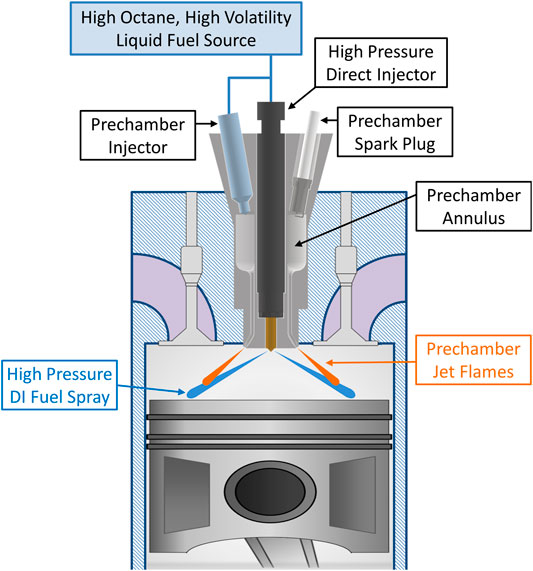
FIGURE 1. Prechamber enabled mixing controlled combustion (PC-MCC) concept.
The fuel must be sufficiently volatile to ensure evaporation and avoid coking or pool fires in the prechamber. Also, the fuel should have sufficiently high resistance to autoignition (i.e., high octane) to avoid premature ignition in the prechamber. The prechamber ignition is trigger by the spark plug to ensure adequate and repeatable control over the prechamber combustion process. Gasoline-like fuels, propane, LNG, and alcohols, such as methanol, ethanol, propanol, and butanol, among others, are excellent candidates for this concept.
This study focused on methanol. Methanol is an attractive biofuel because it can be made from a variety of biomass sources and is the simplest solar fuel for the future (Bromberg and Cheng 2010; Shih et al., 2018). Due to its high heat of vaporization and high resistance to autoignition, it is rather challenging to establish robust MCC operation with methanol. Thus, the PC-MCC strategy is demonstrated with methanol in this study as it will be one of the most challenging fuels to ignite. However, this concept is thought to be fuel flexible and applicable to any fuel with sufficient volatility and resistance to autoignition.
In this work, comparisons are made between conventional diesel combustion (CDC), mixing controlled combustion of methanol doped with a cetane improver (MCC-MD), and the prechamber enabled mixing controlled combustion (PC-MCC) concept with pure methanol fuel. Experimental engine data was acquired from a single-cylinder diesel engine under CDC and MCC-MD operation. A CFD model of the engine was constructed and the model validated for its predictive accuracy of the ignition and combustion processes during CDC and MCC-MD operation. Then, the CFD model was used to demonstrate and study the PC-MCC concept with methanol. Parametric variations of the prechamber size and the passageway diameter were simulated and analyzed. Lastly, the combustion robustness, which is defined as the insensitivity of the combustion process to boundary conditions, was assessed for the three combustion strategies.
Single-Cylinder Experimental Engine
The experiments were carried out on a four-stroke diesel engine based on the General Motors (GM) 1.9 L platform. Table 1 shows the engine geometry and fuel injector specifications. The experimental engine laboratory is at the University of Wisconsin-Madison’s Engine Research Center. The engine has a high pressure common rail fuel system. The direct injector (DI) used in this study was a Bosch CRI2.2 which is centrally mounted in the engine cylinder. The piston bowl was the stock GM 1.9 L diesel piston which has a compression ratio of 16.7 and a re-entrant bowl shape, which was conventional for light-duty diesel engines of this vintage.
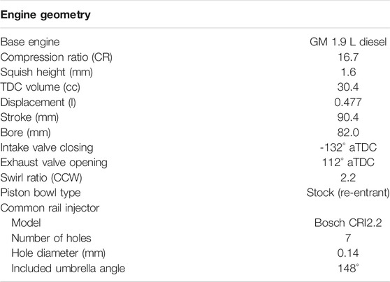
TABLE 1. General motors 1.9 L single-cylinder engine & fuel injector specifications.
For each steady-state operating point, 300 consecutive cycles of cylinder pressure data were acquired. Each individual cycle’s pressure data was smoothed using a Fourier series low-pass filter with a Gaussian roll-off function having a transmission of 100% from 0 to 6 kHz and dropping to 1% at 8 kHz. These frequencies are slightly higher than the first vibration mode for the cylinder bore of this engine. This is done to retain as much information as possible in the cylinder pressure data, yet filter out the high frequency noise, which contains very little useful information and makes the computed heat release rate difficult to interpret (Brunt et al., 1998; Dempsey et al., 2019).
Once filtered, the cylinder pressure traces were used to calculate the apparent heat release rate (AHRR) for each individual cycle. The AHRR is essentially the chemical heat release rate minus the heat loss rate to the combustion chamber walls and is given by
where P is the cylinder pressure, V is the cylinder volume, γ is the ratio of specific heats, and θ is the crank angle. In this work, γ is assumed to be a constant of 1.33. From the AHRR, the accumulated heat release can be calculated. Combustion phasing parameters are calculated, such as CA10, CA50, and CA90, which represent the crank angle location at which the accumulated heat release had reached 10%, 50%, and 90% of its maximum value, respectively. The gross indicated cycle comprises of the compression and expansion strokes only, from −180° to 180° ATDC, where 0° ATDC represents top dead center of the compression stroke. The gross cycle is of interest when studying engine combustion strategies because it focuses on the thermodynamics of the cycle and does not include ancillary affects such as friction and pumping. The gross indicated mean effective pressure (IMEPg) was calculated as
where Vd is the engine displacement volume. The gross indicated efficiency (GIE) measures the efficiency of the combustion and work extraction processes and includes affects from the thermodynamics of the working fluid, heat transfer, incomplete combustion, and cylinder blow-by. The GIE was calculated as
where mfuel is the mass of fuel injected per cycle and LHVfuel is the lower heating value of the fuel.
In this study, a single mid-load steady-state engine operating condition was investigated: 1900 rpm and ∼10 bar IMEPg. Two experimental campaigns were conducted–one with DI diesel fuel and the other with DI methanol blended with 12% by mass di-tert-butyl peroxide (DTBP). The properties of these fuels are shown in Table 2. The diesel fuel was a pump fuel that was analyzed by an independent lab to determine its properties. The methanol was purchased from VP Racing Fuels and is a product referred to as M1 and the properties are taken to be pure methanol from Heywood (Heywood 1988).
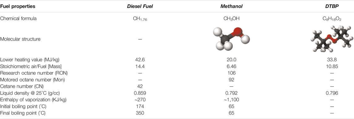
TABLE 2. Fuel properties for pump diesel fuel, methanol, and di-tert-butyl peroxide (DTBP).
DTBP is a commercially available fuel additive that is used in diesel fuel to increase the cetane number (Schwab et al., 1999). It has also been studied as a fuel additive to increase the fuel reactivity of high octane fuels for use in advanced combustion modes, such as HCCI and RCCI (Mack et al., 2005; Splitter and Hanson, 2010; Kaddatz et al., 2012; Dempsey et al., 2013a). Dempsey et al. used lean HCCI engine experiments to characterized the impact of DTBP on the reactivity of high octane fuels, such as gasoline, methanol, and ethanol (Dempsey et al., 2013). The reactivity of the base fuel blended with the cetane improver was assessed via the effective primary reference fuel (PRF) number, which is determined by conducting experiments with the PRF fuels at a matched operating condition. Methanol mixed 12% DTBP by mass had an effective PRF number (i.e., octane number) of ∼72.
The experimental operating conditions are shown in Table 3. Both operating conditions are non-premixed, mixing controlled combustion strategies that use a single injection near top dead center. The conventional diesel combustion (CDC) mode used a lean overall equivalence ratio with no external exhaust gas recirculation (EGR), an injection pressure of 800 bar, and intake conditions that are representative of a turbocharged diesel engine with a charge air aftercooler. A one-dimensional cycle simulation model (GT-Power) of the engine was constructed to predict the trapped cylinder conditions at intake valve closure (IVC) (Dempsey et al., 2013). It was observed that there is a linear relationship between intake surge tank temperature and trapped gas temperature at IVC, which is
where Tivc is the model predicted cylinder gas temperature at IVC and Tintake is the specified boundary condition for the intake surge tank temperature. This relationship is used to initialize the CFD simulations at IVC.
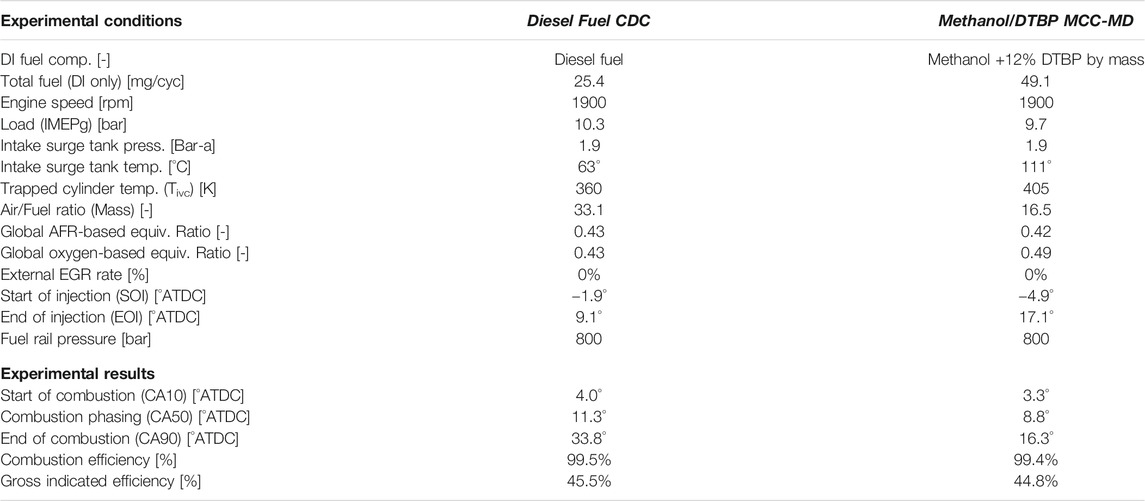
TABLE 3. Experimental operating conditions for single-cylinder GM 1.9 L engine.
The methanol mixed with DTBP strategy, denoted as MCC-MD, was similar with two important differences that stem from the fuel properties. To achieve a similar start of combustion, the MCC-MD strategy required a combination of an earlier start of injection (SOI) and a higher intake temperature. The SOI was advanced by three crank angle degrees (CAD) and the intake temperature was nearly doubled to 111°C. This is a challenge with using high octane fuels in compression ignition engines–they require elevated intake temperatures that can be challenging to achieve in practice while maintaining high engine system efficiency (Jun et al., 2007; Kumar et al., 2017). This study demonstrates that the PC-MCC concept alleviates the need for elevated intake temperatures with high octane fuels.
The CRI2.2 DI injector that was used in the engine experiments was tested on a Bosch tube-style rate of injection (ROI) meter (Bosch 1966; Bower and Foster 1991). The ROI measurements were taken with diesel fuel at a variety of rail pressures and injection durations, all with a fixed tube backpressure of 40 bar. Results of these ROI experiments and more details on how they were conducted can be found in Dempsey (Dempsey 2013). The ROI measurements obtained with diesel fuel for the CRI2.2 injector are used directly in the diesel CFD simulations. The general shape of the measured ROI was maintained from the diesel injection data, but the profile was modified for methanol to account for the fuel density and longer injection duration. This is clearly an assumption that will require closer investigation in the future.
Computational Fluid Dynamics Modeling
In this work, the single-cylinder diesel engine was simulated using the computational fluid dynamics (CFD) modeling code CONVERGE version 2.3.16. CONVERGE uses a modified cut-cell Cartesian method to eliminate the need for the computational grid to fit to the geometry of interest. This approach allows for orthogonal grids and automates the mesh generation process (Senecal et al., 2007). For a detailed description of all the models used in this work, refer to the CONVERGE manual (Richards et al., 2016). The engine is treated as axisymmetric about the cylinder axis, and thus a 1/7th sector geometry was used (i.e., 51.4° sector angle).
The liquid fuel parcels are injected as spheres with the same diameter as the effective injector nozzle hole area but represent a distribution of fuel droplet diameters. In the Eulerian gas phase, Reynolds Averaged Navier-Stokes (RANS) equations are solved to determine the velocity and pressure fields in the engine cylinder. The unclosed stress tensor in the RANS momentum equation is modeled with a turbulent viscosity, which adds to the molecular viscosity. Here, the turbulent viscosity is modeled using the Re-Normalization Group (RNG) k-ε turbulence model. The recommended model constants published by Convergent Science are used throughout this study (Richards et al., 2016). This turbulence model has been validated extensively for RANS simulations of mixing controlled diesel combustion (Dempsey et al., 2018).
Figure 2 shows the simulated sector geometry for the GM 1.9 L engine under the CDC operating condition. The figure shows the location of the liquid fuel parcel injection and provides an illustration of the dynamic computational grid settings used in the model. A base grid resolution of 1.4 mm was used. All cylinder surfaces are embedded with one layer of cells at 0.7 mm resolution. A 10 mm long conical region was embedded with 0.35 mm cells near the injector nozzle to resolve the high velocity spray. Lastly, CONVERGE’s adaptive mesh refinement (AMR) was used to resolve gradients in temperature and velocity with a resolution of 0.35 mm. These Lagrangian-Drop, Eulerian-Fluid spray and mixing models have been shown by previous researchers to be sensitive to the Eulerian grid resolution (Abani et al., 2008; Wang et al., 2010; Dempsey et al., 2012). Research has shown that using a model setup similar to this one, results in acceptable grid convergence of the lift-off length and reaction zone thickness for a diesel spray with cell sizes of 0.35 mm (Senecal et al., 2013a; Senecal et al., 2013b; Pomraning et al., 2014). Thus, this was used as the minimum cell size in this work.
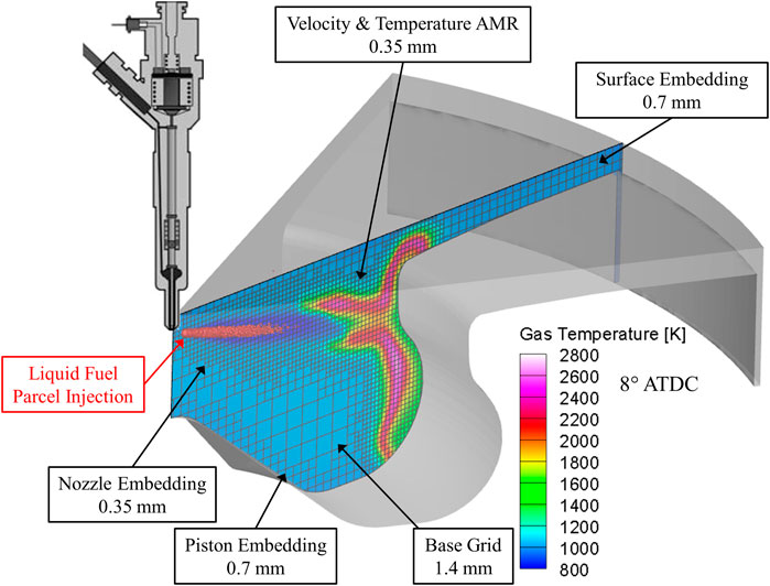
FIGURE 2. Sector simulation of the CDC operating condition illustrating the computational grid settings. Vertical cut plane colored by gas temperature on the spray axis at 8° ATDC.
The physical properties (i.e., density, surface tension, vapor pressure, heat of vaporization, etc.) of liquid diesel fuel are defined as a single component with the properties from CONVERGE’s predefined liquid property database: DIESEL2 (Richards et al., 2016). The physical properties of the methanol/DTBP mixture are taken to be that of pure methanol. Once evaporated into the gas phase, the diesel fuel is chemically simulated as n-heptane and the methanol/DTBP mixture is treated as such, a prescribed binary blend of methanol and DTBP.
The combustion model used was directly integrated chemical kinetics, which are solved using CONVERGE’s SAGE chemistry solver (Richards et al., 2016). Each CFD cell is treated as a well-stirred, homogeneous chemical reactor. There is no sub-grid model accounting for turbulence chemistry interactions. The chemical kinetics model used was that of Wang et al. (Wang et al., 2014). It is a skeletal mechanism consisting of 80 species and 349 elemental reaction pathways. The mechanism includes the primary reference fuels (PRF) n-heptane and iso-octane, as well as methanol, ethanol, and di-tert-butyl peroxide (DTBP). The mechanism was validated by Wang et al. (Wang et al., 2014) for predicting ignition and subsequent combustion during HCCI engine operation with PRF blends and alcohol/DTBP fuel blends. The mechanism accurately predicted the impact of DTBP addition on the ignition delay.
In this work, the oxygen-based equivalence ratio (Φox) will be used. The oxygen-based equivalence ratio is calculated in each CFD cell as
where Ni is the number of moles of species i and ηC,i, ηH,i, and ηO,i are the number of carbon (C), hydrogen (H), and oxygen (O) atoms in species i, respectively (Richards et al., 2016). For pure hydrocarbon fuels, the oxygen-based equivalence ratio and the classic air/fuel ratio-based equivalence ratio are identical. However, for oxygenated fuels, Mueller showed that the oxygen-based equivalence ratio is different than the air/fuel-based equivalence ratio. The oxygen-based method is a more appropriate measure of the instantaneous proximity of the reactant mixture to chemical stoichiometry (Mueller 2005).
Figure 3 compares the experimental cylinder pressure and AHRR to that predicted by the CFD model for CDC and MCC-MD operation. The AHRR from the CFD model is calculated exactly as described earlier for the experiments, using the same band-pass filter and constant specific heat ratio. In both models, the ignition delay is predicted accurately, but the amount of heat release during the “premixed-spike”, which is the first phase of mixing controlled combustion (Dec 1997), is overpredicted by the CFD simulations. This suggests that the mixing rate is overpredicted during the ignition delay period. This is common with RANS CFD models that use well-stirred reactor chemistry, due to artificial overmixing in each discrete cell. The mixing controlled combustion phase is well predicted in both models, both up to the end of injection and after the end of injection.
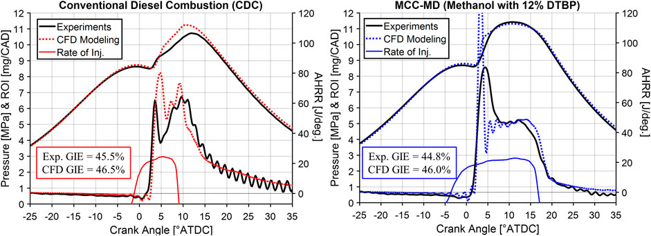
FIGURE 3. Cylinder pressure and AHRR from GM 1.9 L engine experiments and CFD modeling at ∼10 bar IMEPg for CDC (left) and MCC-MD (right) operation.
Also shown in Figure 3 is a comparison between the experimental and CFD predicted GIE. The CFD model is overpredicting the GIE for both operating strategies by ∼1% absolute. However, the trend of slightly decreased GIE by ∼1% absolute from the CDC to MCC-MD strategy is reasonably well captured by the simulations. This slight reduction in efficiency is thought to be due to higher heat transfer losses for the MCC-MD strategy, stemming from the larger premixed heat release event and the longer injection duration, which could lead to an extended period of high in-cylinder heat transfer coefficients at the walls.
The remainder of this study uses CFD simulations to demonstrate a novel prechamber enabled mixing controlled combustion strategy for high octane fuels and demonstrate its desirable characteristics regarding combustion robustness. At this stage of the concept development, pollutant emissions are out of scope and thus no emissions predictions will be shown from the CFD modeling.
CFD Modeling of Prechamber Enabled Mixing Controlled Combustion
CFD simulations were used to demonstrate the concept of using an actively fueled annular prechamber to ignite a direct injected methanol fuel spray, as illustrated in Figure 1. Figure 4 shows how the CFD sector geometry model was modified to include the annular prechamber and passageway. When adding the annular prechamber and the passageway, the engine’s squish height, which is the distance between the top of the piston crown and the firedeck at TDC, is adjusted to maintain a geometric compression ratio (CR) of 16.7. Considering the assumption of vertical axisymmetry, this model would inherently assume that there is one passageway for each DI spray plume, which means seven passageways and seven DI spray plumes in this model. Each DI spray plume would have a hot prechamber jet flame directly above it to serve as an ignition source. This will hopefully alleviate challenges with cyclic variability of the ignition of each methanol plume. Mueller et al. studied glow-plug assisted mixing controlled combustion of methanol and observed that with a single glow-plug, the start of combustion was highly variable, which is undesirable (Mueller and Musculus 2001).
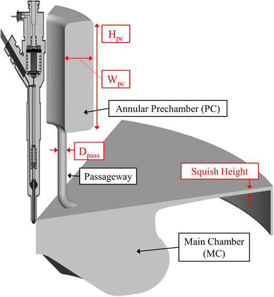
FIGURE 4. CFD sector geometry model of the prechamber enabled mixing controlled combustion concept (PC-MCC) at TDC. Model shown has a prechamber passageway diameter (Dpass) of 1.5 mm and height (Hpc) of 20 mm (D1.5 – H20).
Table 4 shows the geometric specifications of all the prechambers investigated. The passageway diameter (Dpass) and the height of the annular prechamber (Hpc) were parametrically varied in this study, all with the width of the prechamber annulus (Wpc) fixed at 5 mm. The prechamber volume as a percentage of the TDC volume ranges from 7.6% to 19.1%. Figure 5 shows more details of the CFD modeling setup for the PC-MCC simulations. The annular prechamber is wrapped around the centrally mounted common rail direct injector. A schematic of a direct injector is shown to help visualize the system but is of no consequence on the simulations. For the PC-MCC simulations, an additional level of grid refinement is used. The passageway surface is embedded with two layers of 0.175 mm cells, to further refine the flow, combustion, and heat transfer processes in the passageway.
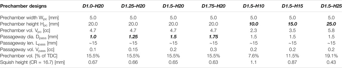
TABLE 4. Variations of annular prechamber and passageway design simulated with CFD model.
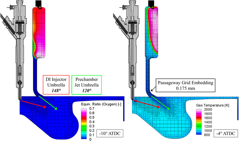
FIGURE 5. Illustration of the CFD modeling setup for the prechamber enabled mixing controlled combustion (PC-MCC) simulations with Dpass = 1.5 mm and Hpc = 20 mm (Left) Vertical cut plane on the spray axis colored by oxygen-based equivalence ratio at PC spark timing (Right) Vertical cut plane on the spray axis colored by gas temperature at the start of DI methanol.
In the PC-MCC CFD simulations, at the top of the annular prechamber an energy source is introduced to simulate a spark plug. The energy source is a small sphere with a diameter of 1.0 mm which protrudes 1.0 mm into the top of the prechamber and is centered in the annulus width. The spark plug is conceptually illustrated in Figure 5. The source releases a small amount of energy in two phases to simulate the breakdown and arc phase of a spark plug (Richards et al., 2016). Considering these are sector simulations, having a spark source in the annular prechamber off the center axis of the domain means there would be seven distinct spark plugs in the full prechamber. This is not what is intended for this concept. Rather, as illustrated in Figure 1, it is intended to only use a single spark ignition source. The effect of the seven distinct ignition sites will likely lead to an overprediction of the burn rate in the prechamber, but still allows for this simple CFD model to provide a proof-of-concept for this combustion strategy and illustrates its strengths and weaknesses.
The PC-MCC simulations use the same operating conditions as the MCC-MD strategy in Table 3, with some marked differences. The initial gas temperature at IVC (i.e., the start of the CFD simulation) in the prechamber and the passageway was set to 450 K. This is an estimate but was set relatively high to consider that these regions will remain hot from the previous cycle. The main chamber’s initial temperature was set at 360 K. This demonstrates that the PC-MCC concept does not need high levels of intake heating for high octane fuels. In this case, the intake surge tank temperature being simulated is 63°C, just as was used with CDC operation.
The passageway and the main combustion chamber are initialized with dry air (21% O2 and 79% N2 by mole). For all PC-MCC simulations conducted in this study, the prechamber was initialized with a homogenous mixture of methanol and dry air at an oxygen-based equivalence ratio of 3.7. This is an arbitrary value, but it will be shown that this results in a lean, yet ignitable mixture in the prechamber at spark timing. This prechamber initialization is a simplification to demonstrate the concept. In practice, there would be a fuel injector that delivers fuel into the prechamber during the compression stroke. Considering all prechambers begin with a Φox of 3.7, the prechamber total methanol fueling depends on the prechamber volume. The prechambers with a height of 20 mm and a volume of 4.7 cc, used 7.5 mg/cyc of methanol. The prechambers with 10 mm, 15 mm, and 25 mm heights had prechamber fuel quantities of 3.7 mg/cyc, 5.6 mg/cyc, and 9.4 mg/cyc, respectively. These prechamber fuel quantities are for the full prechamber annulus and not just the sector geometry. Finally, the DI methanol fueling remained fixed at 49.1 mg/cyc with an SOI timing of −4.9° ATDC.
As shown on the left in Figure 5, during the compression stroke, air from the main chamber is pushed up into the prechamber, creating a progressively leaner mixture throughout compression. At prechamber spark timing (−10 °ATDC), the mixture is no longer homogeneous in the prechamber. The mixture is leanest right above the passageway and in the lower right corner of the prechamber there is a near stoichiometric mixture. At the spark plug the Φox is ∼0.5 for this prechamber design. Figure 6 shows the prechamber spatially averaged Φox during the compression stroke for the various prechambers. All cases started with a homogenous Φox of 3.7 at IVC and become progressively leaner during compression. At spark timing (-10 °ATDC), the average Φox in the prechamber ranges from ∼0.45 to ∼0.65. This will impact the burn rate, flame temperature, and pressure rise rate in the prechamber.
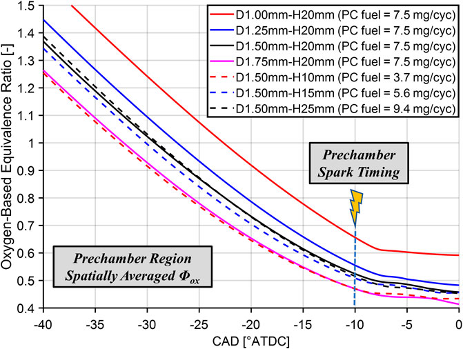
FIGURE 6. Evolution of the spatially averaged oxygen-based equivalence ratio (Φox) in the prechamber during the compression stroke for each prechamber geometry investigated.
Demonstration of Prechamber Enabled Mixing Controlled Combustion (PC-MCC) With Pure Methanol Fuel
To illustrate the PC-MCC concept, CFD simulation results are shown in Figure 7 using the prechamber with a height of 20 mm and a passageway diameter of 1.5 mm. The bottom of Figure 7 shows the prechamber and main chamber pressure, the prechamber and main chamber heat release rate (HRR), and the DI methanol ROI profile, all as a function of crank angle. The top row of the figure shows an in-cylinder images of predicted gas temperature. There are two cut planes, one vertical and one on the umbrella angle of the injector, both co-incident with the DI spray axis.
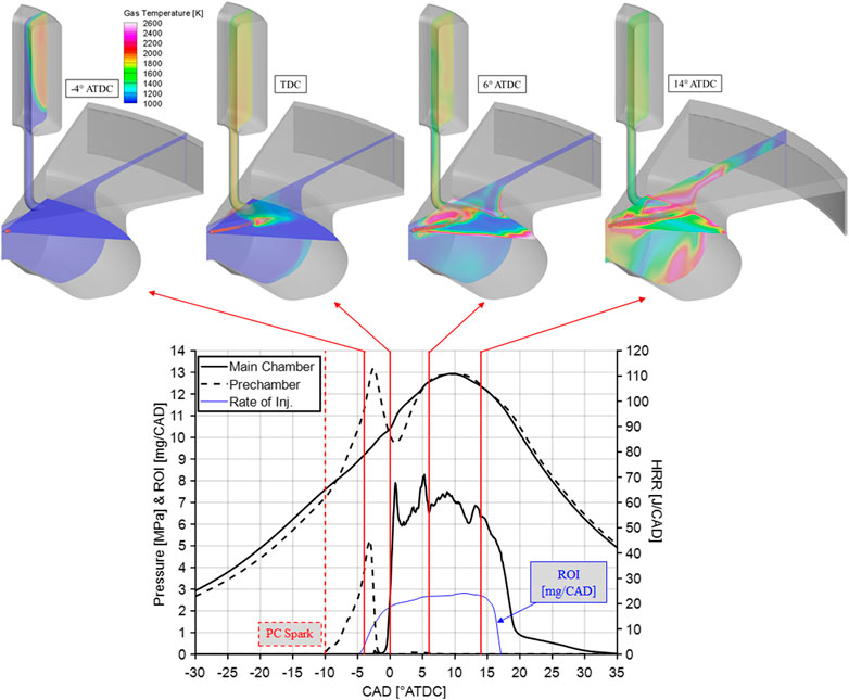
FIGURE 7. Prechamber enabled mixing controlled combustion (PC-MCC) operated on pure methanol. Prechamber height (Hpc) of 20 mm and passageway diameter (Dpass) of 1.5 mm. Prechamber spark timing of -10 °ATDC and DI-SOI methanol of -4.9 °ATDC.
During compression, the prechamber pressure lags the main chamber slightly, which is expected as mass is pushed from the main chamber to the prechamber through the passageway. If the fuel has a high resistance to autoignition, then pre-ignition in the prechamber should not be a concern. At −10°ATDC, the spark ignition source begins at the top center of the prechamber. The heat release duration in the prechamber is predicted to be ∼9 CAD, which is relatively fast. The prechamber burn duration is predicted to be very short due to the seven distinct ignition sources, as modeled by the sector geometry. Due to the combustion in the prechamber, the prechamber pressure rises to a max of 13 MPa at −3°ATDC, while the main chamber pressure is at 9.5 MPa. This pressure difference ejects at hot jet flame out of the prechamber at approximately top dead center.
The DI methanol is already being injected into the main chamber and the prechamber jet almost immediately ignites the DI methanol fuel spray and establishes a MCC event in the main chamber. The combustion in the main chamber evolves spatially in a manner like CDC operation, with the non-premixed flame advected down into the bottom of the bowl along the reentrant bowl wall and up into the squish region. The combustion rate in the main chamber is relatively constant from the start of combustion to the end of combustion and is controlled by the rate of injection of the DI methanol fuel and the subsequent turbulent mixing created by the spray, piston motion, and the spray/wall interaction. This is the ideal situation to control the combustion process because it can be tailored through the design of the fuel injector (number of holes, flowrate, and spray angle), the piston bowl shape, the injection timing, and the in-cylinder bulk motion. This is a controllable combustion process, which is key for real-world propulsion applications.
CFD Modeling of Variations in Prechamber Design
Figure 8 shows the results of varying the passageway hole diameter from 1.0 to 1.75 mm. Each case has the same overall operating condition. Each prechamber is fueled with 7.5 mg/cyc of methanol and 49.1 mg/cyc of methanol are direct injected. At spark timing (−10 °ATDC), the average Φox values range from ∼0.65 for the smallest passageway and ∼0.45 for the largest passageway, as shown in Figure 6. The small 1.0 mm passageway is clearly too restrictive, as the prechamber pressure significantly lags the main chamber pressure. This results in “pumping” losses as mass is exchanged between to the two chambers. This is reflected in the low CFD predicted GIE of 42.7%.
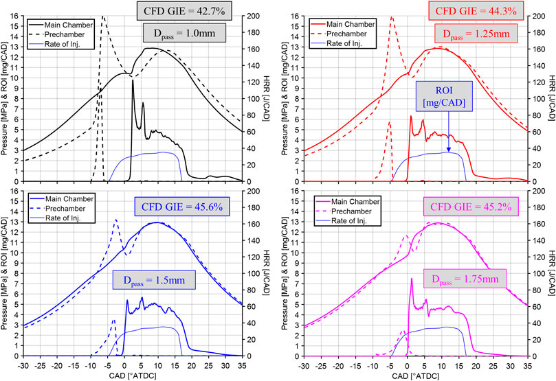
FIGURE 8. CFD predicted pressure and heat release rate for PC-MCC operation over a parametric sweep of passageway diameter. Operation is with pure methanol fuel.
As the passageway size is increased, the prechamber pressure follows the main chamber pressure more closely and the GIE increases with a maximum value of 45.6% for the 1.5 mm diameter prechamber. This indicated efficiency is near the CFD predicted values for CDC (GIECDC = 46.5%) and MCC-MD (GIEMCC-MD = 46.0%) operation. The slightly lower efficiency for PC-MCC operation is thought to be due to the additional heat transfer losses in the prechamber and passageway, but this will require further investigation to confirm. These losses, as well as the chamber-to-chamber pumping losses, could potentially be reduced by reducing the prechamber size and passageway length.
Another parametric variation of the prechamber design focused on the size of the prechamber. The height of the prechamber was varied from 10 mm to 25 mm, always using a passageway diameter of 1.5 mm. The prechamber fueling varies with prechamber size, from 3.7 mg/cyc to 9.4 mg/cyc. Figure 6 shows how the prechamber average Φox values vary during compression up to spark timing. Figure 9 shows the results of the CFD simulations of varying prechamber height. The shortest prechamber (Hpc = 10 mm) resulted in a total misfire of the DI methanol fuel. This due to the low prechamber fueling which resulted in the prechamber jet flames being weak with very little penetration into the main chamber. Increasing the prechamber height to 15 mm, resulted in combustion of the DI methanol in the main chamber, but with a longer ignition delay of ∼12 CAD, as compared to larger prechambers, which have an DI methanol ignition delay of ∼5 CAD. The longer ignition delay results in a partially premixed combustion event, which does yield comparable indicated efficiency, but tends to increase combustion generated noise (Dempsey et al., 2016). The 20 mm and 25 mm tall prechambers yield very similar combustion processes, but the larger prechamber has lower GIE, likely stemming from high heat transfer losses in the prechamber due to the increased surface area.
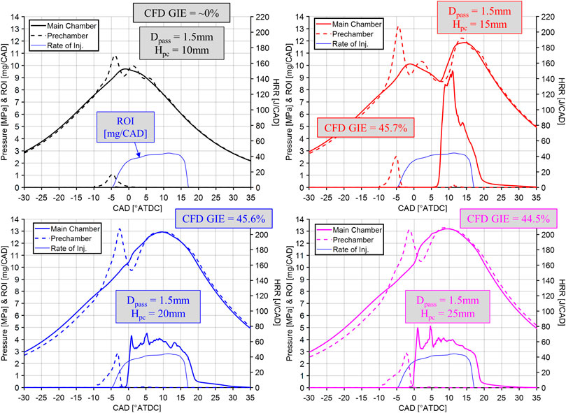
FIGURE 9. CFD predicted pressure and heat release rate for PC-MCC operation over a parametric sweep of prechamber height. Operation is with pure methanol fuel.
The last parametric variation of the PC-MCC strategy investigated in this study was the impact of the prechamber spark timing. The prechamber spark timing was varied from −25° to −10° ATDC using the 20 mm tall prechamber with a 1.5 mm diameter passageway. The DI methanol fueling was fixed using the same ROI and SOI of −4.9° ATDC, as it has been throughout this investigation. It is important to remember that the oxygen-based equivalence ratio in the prechamber varies with spark timing, as illustrated in Figure 6.
The results of the spark timing sweep are shown in Figure 10. The latest spark timing of −10 °ATDC, yields the shortest DI methanol ignition delay and a very steady mixing controlled heat release rate. As the prechamber spark timing is advanced, the main chamber heat release rate is delayed considerably, which results in a progressively decreasing GIE. Interestingly, the start of combustion is relatively constant in the main chamber for the three advanced prechamber spark timings. Figure 10 shows the maximum and average gas temperature in the main chamber as a function of crank angle for the various spark timing simulations. For the latest spark timing of -10 °ATDC, the hot prechamber jet flame enters the main chamber at ∼ −2.5 °ATDC, immediately impacting the DI methanol fuel spray, which started at −4.9 °ATDC. However, for the more advanced spark timings, the prechamber jet flame enters the main chamber before the DI injection of methanol. In these cases, the jet flame is serving to preheat the main chamber, but not directly ignite the DI methanol spray.
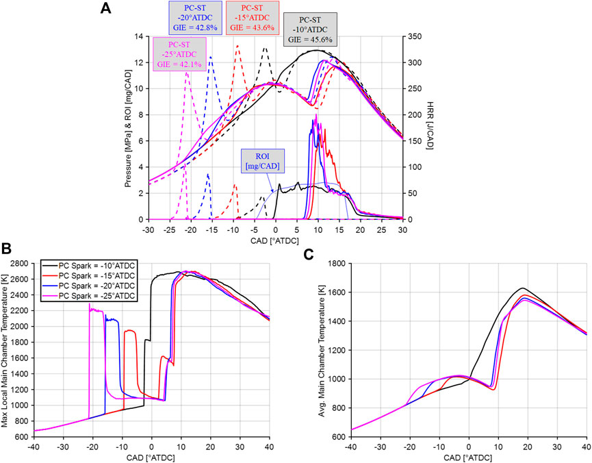
FIGURE 10. CFD predicted A.) pressure and heat release rate, B.) maximum main chamber temperature, and C.) average main chamber temperature for PC-MCC operation with pure methanol over a parametric sweep of the prechamber spark timing. Prechamber height of 20 mm and passageway diameter of 1.5 mm.
For the advanced spark timings, the jet flame enters the main chamber several crank angle degrees after the spark, as indicated by a rapid increase in the maximum main chamber temperature. The peak temperature of the jet flame is dependent on the equivalence ratio in the prechamber, which is higher for earlier spark timings, and results in a higher jet flame temperature entering the main chamber. Once the pressure in the prechamber decreases back to the main chamber level, the ejection of a hot jet from the prechamber ceases abruptly. The high temperature jet in the main chamber mixes out rapidly and the peak main chamber temperatures for the three advanced spark timings all converge to ∼1100 K by TDC. This results in a relatively constant ignition delay of the DI methanol spray, which is longer than if the DI methanol was ignited directly by the prechamber jet flame.
Demonstration of Combustion Robustness of Prechamber Enabled Mixing Controlled Combustion
The primary motivation of PC-MCC is to allow the use high octane fuels in a combustion mode that retains all the advantages of CDC, such as robustness, consistency, controllability, non-knock limited operation, and high efficiency. Robustness is defined as the combustion process being insensitive to engine boundary conditions, such that the engine is resilient and unaffected by varying environmental conditions, transients, cylinder-to-cylinder and cycle-to-cycle variations in trapped conditions, and varying fuel injection processes. To illustrate combustion robustness, the in-cylinder IVC temperature is varied widely in the CFD simulations for the various combustion strategies studied: CDC with diesel fuel, MCC-MD with various mixtures of methanol and DTBP, and PC-MCC with pure methanol. The results are shown in Figure 11. In Figure 11A secondary x-axis illustrates the estimated intake surge tank temperature required to achieve the prescribed in-cylinder IVC temperature, which was determined from Eq. 4 using a one-dimensional engine model.
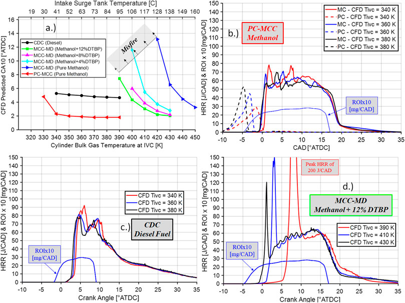
FIGURE 11. A.) CFD predicted start of combustion (CA10) over an intake temperature sweep for CDC with diesel fuel, MCC-MD with various blends of methanol and DTBP, and PC-MCC operation with pure methanol. B.), C.), and D.) CFD predicted heat release rates for the various mixing controlled combustion strategies over a variation of intake temperature. PC-MCC simulations conducted with a 20 mm tall prechamber with a 1.5 mm passageway.
Conventional diesel combustion (CDC) demonstrates combustion robustness, as the start of combustion is essentially constant while the intake temperature was varied over a span of ∼55°C. PC-MCC operation with pure methanol and the 20 mm tall prechamber with a 1.5 mm diameter passageway also demonstrates excellent combustion robustness over a similar range of intake temperatures. This is extremely important and suggests that the PC-MCC strategy maintains an insensitivity to intake temperature, which is a desirable characteristic.
MCC-MD operation yields different results. The start of combustion shows significant sensitivity to the intake temperature, for all methanol/DTBP mixtures investigated. As the DTBP concentration is reduced from 12% by mass to 0% by mass (pure methanol), the intake temperature requirements increase significantly. For pure methanol, to have combustion phasing similar to CDC and PC-MCC operation, the intake temperature required is ∼160°C, which is quite high and difficult to achieve over a wide operating space in a real world propulsion application.
Finally, Figure 11 also shows various examples of the CFD predicted heat release rates over the variations in intake temperature. CDC and PC-MCC operation are robust to the widely varying intake temperature as the main chamber heat release rate is essentially unaffected. For PC-MCC, the prechamber heat release is affected by the main chamber IVC temperature variation. This is likely the result of several factors. The air density in the main chamber increases as the intake temperature decreases, thus more air is transferred to the prechamber during the compression processes, reducing the equivalence ratio in the prechamber at spark timing. Also, as the intake temperature decreases, the unburned gas temperature in the prechamber decreases, resulting in lower flame speed in the prechamber. The start of combustion for MCC-MD operation is rather sensitive to trapped IVC temperature. This sensitivity results in widely varying peak heat release rates during the premixed combustion phase, which will result in widely varying engine noise and create combustion timing controllability challenges.
Summary and Conclusion
This study focused on developing a combustion concept that would allow high octane fuels to be utilized in a mixing controlled combustion strategy. The concept used an annular prechamber and a center-mount high pressure direct injector. The fuel used in this study was methanol, which is a very suitable candidate fuel for this concept. However, the PC-MCC concept is fuel flexible, as long as the fuel has sufficient volatility and relatively high resistance to autoignition to avoid premature ignition in the prechamber.
This work used single-cylinder engine experiments to demonstrate the performance of mixing controlled combustion with diesel fuel (CDC) and mixing controlled combustion with methanol/DTBP blends (MCC-MD). A CFD model was constructed to simulate these combustion strategies and the PC-MCC concept fueled with pure methanol. The following summarizes the findings of this investigation.
1. MCC-MD operation with direct injected methanol mixed with 12% by mass DTBP was successfully used a replacement for diesel fuel at mid-load operating condition in a light-duty CI engine—1900 rpm and ∼10 bar IMEPg. Compared to diesel fuel, to achieve a similar start of combustion, the injection timing was advanced by ∼3 CAD and the intake temperature was nearly doubled to 111°C.
2. The MCC-MD strategy yielded diesel-like GIE, but it was demonstrated that MCC-MD lacked combustion robustness, as the start of combustion was very sensitive to the trapped IVC temperature. This was the case for varying levels of DTBP mixed with methanol and for pure methanol. One of the advantages of CDC operation is combustion robustness to varying boundary conditions. Thus, for clean burning alternatives to diesel fuel to be used in MCC engines, they must be able to demonstrate combustion robustness. It appears that reactivity enhanced methanol does NOT demonstrate combustion robustness at the conditions investigated here.
3. The PC-MCC strategy using pure methanol demonstrated an insensitivity to varying intake temperature and thus a similar level of combustion robustness compared to CDC operation. The PC-MCC strategy was parametrically studied with methanol, varying the prechamber size, passageway diameter, and prechamber spark timing. A passageway diameter of 1.5 mm yielded the highest GIE. A prechamber size of at least 3.5 cc was needed to achieve prechamber jet flames that penetrated the main chamber to ignite the DI methanol spray. The prechamber spark timing sweeps revealed that there are essentially two PC-MCC operating regimes: one in which the prechamber jet flames directly ignite the DI fuel spray and a second where the prechamber is fired sufficiently early, in which case the prechamber jet flames simply preheat the main combustion chamber.
Future Work & Vision Looking Forward
Based on the findings in this study, the PC-MCC combustion strategy can deliver diesel-like indicated efficiency and maintain the combustion robustness that is expected in a diesel engine application. The PC-MCC concept was demonstrated here with methanol, but it is expected to be a strategy that could utilize a wide variety of fuels, such as gasoline, propane, LNG, and alcohols. The research conducted in this study was simply a proof-of-concept and by no means an optimization. There are many areas of investigation needed to further develop this combustion strategy. The primary focus of future research in this area will need to address the following:
1. Future CFD simulations need to be conducted on a full engine geometry. Thus, the annular prechamber can be fully represented and the fuel spray and mixture formation process in the prechamber can be modeled. A more accurate representation of the spark ignition source and prechamber flame propagation should be included. With the full prechamber geometry being considered, the passageway length, angle, and quantity can be optimized as well. Future CFD simulations need to conduct grid convergence studies to build confidence in the simulation results.
2. Using the full geometry CFD model, PC-MCC should be demonstrated with a wide variety of fuels, looking at the requirements for volatility considering the fuel injection into the prechamber and the requirements for reactivity to avoid premature ignition in the prechamber.
3. The operating space needs to be developed for each fuel. For instance, the prechamber does not need to be fired at all conditions. An engine could be started, idled, and operated at low load with the prechamber and PC-MCC operation. However, as the load is increased, lower octane fuels, such as naphtha and lower octane gasolines, would likely not require the prechamber’s assistance to achieve MCC operation. For fuels that have a higher resistance to autoignition, such as alcohols and natural gas, they may require the prechamber to be used at all conditions. Lastly, there are perhaps operating conditions where the actively fueled prechamber could be used as turbulent jet ignition source for a stoichiometric premixed charge, in which case the direct injector would not be used.
4. In this study, the inside radius of the annular prechamber was 5 mm and the outside radius was 10 mm. Thus, the direct injector used in this system would have an injector body diameter of no larger than 10 mm. This is relatively small for current state-of-the art direct fuel injectors and thus the impact of this assumption will need to be studied in future investigations of this concept. Then, an annular prechamber with a suitable direct injector can be constructed and tested.
5. Lastly, the emissions from PC-MCC operation need to be quantified and understood. When using highly oxygenated fuels like low carbon alcohols, it is likely that will be very little to no soot emissions. However, PC-MCC will certainly have high engine-out NOx emissions. For very low sooting fuels, there may be an opportunity to use stoichiometric PC-MCC operation and utilize a three-way catalyst for NOx control. These types of thoughts need further investigation to be realized.
Data Availability Statement
The raw data supporting the conclusions of this article will be made available by the authors, without undue reservation.
Author Contributions
AD is lead author and did the writing and prechamber simulations. JZ designed the annular prechambers. MW conducted the CDC and MCC simulations.
Conflict of Interest
The authors declare that the research was conducted in the absence of any commercial or financial relationships that could be construed as a potential conflict of interest.
Acknowledgments
The authors would like to acknowledge Convergent Science for use of academic licenses for CONVERGE and TECPLOT. A special thanks to the Marquette University HPC team for maintaining the cluster. The authors would like to acknowledge Casey Allen (Marquette University), Jim Szybist (Oak Ridge National Laboratory), Sage Kokjohn (University of Wisconsin-Madison), and Ben Lawler (Clemson University) for helpful conversations and lastly Rolf Reitz for the use of the engine data from the University of Wisconsin-Madison.
References
Abani, N., Kokjohn, S., Park, S. W. M. Bergin, Munnannur, A., Ning, W., Sun, Y., et al. (2008). “An improved spray model for reducing numerical parameter dependencies in diesel engine CFD simulations,” in SAE World Congress & Exhibition, Detroit, MI, April, 2018. doi:10.4271/2008-01-0970
Bosch, W. (1966). The fuel rate indicator: a new measuring instrument for display of the characteristics of individual injection. SAE International, Technical Paper 660749. doi:10.4271/660749
Bower, G. R., and Foster, D. E. (1991). “A comparison of the Bosch and zuech rate of injection meters,” in International congress & exposition (Warrendale, Pennsylvania: SAE International) doi:10.4271/910724
Bromberg, L., and Cheng, W. K. (2010). Methanol as an alternative transportation fuel in the U.S.: options for sustainable and energy-secure transportation. Cambridge, England: Sloan Automotive Laboratory, Massachusetts Institute of Technology.
Brunt, M. F. J., Pond, C. R., and Biundo, J. (1998). Gasoline engine knock analysis using cylinder pressure data,” in International congress & exposition (Warrendale, Pennsylvania: SAE International. doi:10.4271/980896
Dec, J. E. (1997). A conceptual model of DI diesel combustion based on laser sheet. SAE International, Technical Paper 970873.
Dempsey, A. B., Curran, S. J., and Wagner, R. M. (2016). A perspective on the range of gasoline compression ignition combustion strategies for high engine efficiency and low NOx and soot emissions: effects of in-cylinder fuel stratification. Int. J. Engine Res. 17 (8), 897–917. doi:10.1177/1468087415621805
Dempsey, A. B., Seiler, P. J., and Johnson, S. (2019). Comparison of cylinder pressure measurements on a heavy-duty diesel engine using a switching adapter. J. Eng. Gas Turbines Power 141 (8), 81014. doi:10.1115/1.4043408
Dempsey, A. B., Seiler, P., Svensson, K., and Qi, Y. (2018). A comprehensive evaluation of diesel engine CFD modeling predictions using a semi-empirical soot model over a broad range of combustion systems. SAE Int. J. Engines 11 (6), 1399–1420. doi:10.4271/2018-01-0242
Dempsey, A. B., Walker, N. R., and Reitz, R. (2013). Effect of cetane improvers on gasoline, ethanol, and methanol reactivity and the implications for RCCI combustion. SAE Int. J. Fuels Lubricants 6 (1), 170–187. doi:10.4271/2013-01-1678
Dempsey, A. B., Walker, N. R. E. Gingrich, and Reitz, R. D. (2014). Comparison of low temperature combustion strategies for advanced compression ignition engines with a focus on controllability. Combustion Sci. Technology 186 (2), 210–241. doi:10.1080/00102202.2013.858137
Dempsey, A. B. (2013). Dual-fuel reactivity controlled compression ignition (RCCI) with alternative fuels. PhD Dissertation. Madison (WI): University of Wisconsin-Madison.
Dempsey, A. B., Walker, N. R., and Reitz, R. D. (2013a). Effect of cetane improvers on gasoline, ethanol, and methanol reactivity and the implications for RCCI combustion. SAE Int. J. Fuels Lubr. 6 (1), 170–187. doi:10.4271/2013-01-1678
Dempsey, A. B., Walker, N. R., and Reitz, R. D. (2013b). Effect of piston bowl geometry on dual fuel reactivity controlled compression ignition (RCCI) in a light-duty engine operated with gasoline/diesel and methanol/diesel. SAE Int. J. Engines 6 (1), 78–100. doi:10.4271/2013-01-0264
Dempsey, A. B., Wang, B.-L., Reitz, R. D., Petersen, B., Sahoo, D., and Miles, P. C. (2012). Comparison of quantitative in-cylinder equivalence ratio measurements with CFD predictions for a light duty low temperature combustion diesel engine. SAE Int. J. Engines 5 (2), 162–184. doi:10.4271/2012-01-0143
Heywood, J. B. (1988). Internal combustion engine fundamentals. New York, NY: McGraw-Hill Book Company.
Jun, J. H., Song, S. H., Chun, K. M., and Lee, K. S. (2007). “Comparison of NOx level and BSFC for HPL EGR and LPL EGR system of heavy-duty diesel engine.” in Asia pacific automotive engineering conference. August 5–August 8, 2018, Hollywood, CA, SAE International. doi:10.4271/2007-01-3451
Kaddatz, J., Andrie, M., Reitz, R., and Kokjohn, S. (2012). Light-duty reactivity controlled compression ignition combustion using a cetane improver. SAE International, Technical Paper 2012-01-1110.
Kalghatgi, G. (2018). Is it really the end of internal combustion engines and petroleum in transport?. Appl. Energ. 225, 965–974. doi:10.1016/j.apenergy.2018.05.076
Kammel, G., Mair, F., Zelenka, J., Lackner, M., Wimmer, A., Kogler, G., et al. (2019). Simulation based predesign and experimental validation of a prechamber ignited HPDI gas combustion concept. SAE International, Technical Paper 2019-01-0259. doi:10.4271/2019-01-0259
Kumar, P., Zhang, Y., Traver, M., and Cleary, D. (2017). Simulation-Guided air system design for a low reactivity gasoline-like fuel under partially-premixed combustion in a heavy-duty diesel engine. SAE International, Technical Paper 2019-01-0259. doi:10.4271/2017-01-0751
Mack, J. H., Dibble, R. W., Buchholz, B. A., and Flowers, D. L. (2005). The effect of the di-tertiary butyl peroxide (DTBP) additive on HCCI combustion of fuel blends of ethanol and diethyl ether. SAE International, Technical Paper 2005-01-2135.
McTaggart-Cowan, G., Mann, K., Huang, J., Singh, A., Patychuk, B., Zheng, Z. X., and Munshi, S. (2015). Direct injection of natural gas at up to 600 bar in a pilot-ignited heavy-duty engine. SAE Intern. J. of Eng. 8 (3), 981–996. doi:10.4271/2015-01-0865
McTaggart-Cowan Mann, G. K., Wu, N., and Munshi, S. (2014). An efficient direct-injection of natural gas engine for heavy duty vehicles. Warrendale, Pennsylvania: SAE International. doi:10.4271/2014-01-1332
Mueller, C. J., and Musculus, M. P. (2001). Glow plug assisted ignition and combustion of methanol in an optical DI diesel engine. Warrendale, Pennsylvania: SAE International. doi:10.4271/2001-01-2004
Mueller, C. J. (2005). The quantification of mixture stoichiometry when fuel molecules contain oxidizer elements or oxidizer molecules contain fuel elements. SAE International, Technical Paper 2005-01-3705.
Mumford, D., Goudie, D., and Saunders, J. (2017). “Potential and challenges of HPDI,” in 9 th AVL international commercial powertrain conference 2017, May 10–11, 2017, Graz, Austria. Warrendale, Pennsylvania: SAE International. doi:10.4271/2017-01-1928
Olivetti, E. A., Ceder, G., Gaustad, G. G., and Fu, X. (2017). Lithium-ion battery supply chain considerations: analysis of potential bottlenecks in critical metals. Joule 1 (2), 229–243. doi:10.1016/j.joule.2017.08.019
Pomraning, E., Richards, K., and Senecal, P. K. (2014). Modeling turbulent combustion using a RANS model, detailed chemistry, and adaptive mesh refinement. SAE International, Technical Paper 2014-01-1116.
Richards, K. J., Senecal, P. K., and Pomraning, E. (2016). Converge v2.3 Manual. Madison, WI: Convergent Science.
Schwab, S. D., Guinther, G. H., Henly, T. J., and Miller, K. T. (1999). The effects of 2-ethylhexyl nitrate and di-tertiary-butyl peroxide on the exhaust emissions from a heavy-duty diesel engine. SAE International, Technical Paper 1999-01-1478. doi:10.4271/1999-01-1478
Senecal, P. K., Pomraning, E., Anders, J. W., Weber, M. R., Gehrke, C. R., Polonowski, C. J., et al. (2013a). Predictions of transient flame lift-off length with comparison to single-cylinder optical engine experiments. 136 (11), 111505. doi:10.1115/1.4027653
Senecal, P. K., Pomraning, E., Richards, K. J., and Som, S. (2013b). An investigation of grid convergence for spray simulations using an LES turbulence model. SAE International, Technical Paper 2013-01-1083.
Senecal, P. K., Richards, K. J., Pomraning, E., Yang, T., Dai, M. Z., McDavid, R. M., et al. (2007). A new parallel cut-cell cartesian CFD code for rapid grid generation applied to in-cylinder diesel engine simulations. SAE International, Technical Paper 2007-01-0159. doi:10.4271/2007-01-0159
Shih, C. F., Zhang, T., Li, J., and Bai, C. (2018). Powering the future with liquid sunshine. Joule 2 (10), 1925–1949. doi:10.1016/j.joule.2018.08.016
Splitter, D., and Reitz, R. D. (2010). High efficiency, low emissions RCCI combustion by use of a fuel additive. SAE Int. J. Fuels Lubr. 3 (2), 742–756. doi:10.4271/2010-01-2167
Tountas, A. A., Peng, X., Tavasoli, A. V., Duchesne, P. N., Dingle, T. L., Dong, Y., et al. (2019). Towards solar methanol: past, present, and future 6 (8), 1801903. doi:10.1002/advs.201801903 |
Wang, H., Dempsey, A. B., Yao, M., Jia, M., and Reitz, R. D. (2014). Kinetic and numerical study on the effects of di-tert -butyl peroxide additive on the reactivity of methanol and ethanol. Energy and Fuels 28 (8), 5480–5488. doi:10.1021/ef500867p
Wang, Y., Ge, H.-W., and Reitz, R. D. (2010). Validation of mesh- and timestep- independent spray models for multi-dimensional engine CFD simulation. SAE Int. J. Fuels Lubr. 3 (1), 277–302. doi:10.4271/2010-01-0626
Keywords: engines, combustion, fuels, prechamber, mixing controlled combustion, renewable fuels, biofuels, methanol
Citation: Dempsey AB, Zeman J and Wall M (2021) A System to Enable Mixing Controlled Combustion With High Octane Fuels Using a Prechamber and High-Pressure Direct Injector. Front. Mech. Eng 7:637665. doi: 10.3389/fmech.2021.637665
Received: 04 December 2020; Accepted: 18 January 2021;
Published: 18 March 2021.
Edited by:
Stephen Busch, Sandia National Laboratories (SNL), Livermore, CA, United StatesReviewed by:
Leonid Tartakovsky, Technion Israel Institute of Technology, IsraelHu Wang, Tianjin University, China
Copyright © 2021 Dempsey, Zeman and Wall. This is an open-access article distributed under the terms of the Creative Commons Attribution License (CC BY). The use, distribution or reproduction in other forums is permitted, provided the original author(s) and the copyright owner(s) are credited and that the original publication in this journal is cited, in accordance with accepted academic practice. No use, distribution or reproduction is permitted which does not comply with these terms.
*Correspondence: Adam B. Dempsey, YWRhbS5kZW1wc2V5QG1hcnF1ZXR0ZS5lZHU=