 Gaurav Handa
 Bradley Denton
 Sankar Rengarajan
 Christopher Chadwell
 Graham Conway
95% of researchers rate our articles as excellent or good
Learn more about the work of our research integrity team to safeguard the quality of each article we publish.
Find out more
ORIGINAL RESEARCH article
Front. Mech. Eng. , 26 March 2021
Sec. Engine and Automotive Engineering
Volume 7 - 2021 | https://doi.org/10.3389/fmech.2021.601397
This article is part of the Research Topic Boosting and Air Handling Technologies for Advanced Power Systems View all 8 articles
Internal combustion engines will be a part of personal transportation for the foreseeable future. One recent trend for engines has been downsizing which enables the engine to run more favorably over regulatory drive cycles. Another shift due to downsizing is the increase in engine power density which leads to problems with engine knock. One way to reduce the knock propensity of engines is by introducing Exhaust Gas Recirculation (EGR) into the combustion chamber. Exhaust Gas Recirculation also helps improve fuel economy and can reduce NOX emissions. EGR reduces volumetric efficiency which places challenges on the boosting system. LP-EGR helps to lower backpressure and improves scavenging which helps reduce knock and operate at a high efficiency at the low-speed and high-load conditions. At high-speed, and high-load operation however, LP-EGR operation can choke the compressor. This would mean that the turbocharger would need resizing to allow a higher mass flow at these higher speed-load conditions. The HP-EGR helps by reducing the flow rates to the compressor at the higher speed-load conditions which avoids compressor choke and permits a full load performance while retaining a smaller, more transient capable turbocharger. The concept of a one-way valve in the HP-EGR Loop has been explored in this paper. During HP-EGR operation, pressure pulsations drive the intake air back through the HP-EGR Loop and limit the maximum amount of HP-EGR. A one-way valve would prevent any backflow and permit a greater HP-EGR flow for a given average delta pressure. For a given EGR rate, this enables a wider throttle position and thus better controllability at the higher speed-load conditions. Engine testing with the one-way valve suggested that the HP-EGR rate at the high speed/load condition was nearly doubled while reducing the PMEP with an improvement in the Brake Specific Fuel Consumption . Additionally, this led to more reasonable actuator positions in terms of the EGR valve and the intake throttle to ensure better controllability.
The increasingly stringent emissions regulations in the diesel engine industry has led to research in Exhaust Gas Recirculation (EGR) technology to reduce engine out NOX. The thermal, chemical and dilution effects of EGR help in mitigating NOX from an engine. Traditionally, high pressure EGR has been used in this application for several decades (Park et al., 2014). Various layouts of EGR have been tried to test their impacts on the performance and emissions of an engine (Mao et al., 2015; Zheng et al., 2004; Vitek et al., 2008) and a dual loop concept which incorporates a high-pressure loop EGR (HP-EGR) and a low-pressure loop EGR (LP-EGR) is born out of these.
In an LP-EGR system, the exhaust gases are extracted from the low-pressure side of the turbine and introduced in the low-pressure side of the compressor (Figure 1A). The primary advantage of an LP-EGR system is that the turbine match, and, subsequently the pressure differential across the engine is unaffected. Since the compressor can be sized differently from the turbine, the LP-EGR system has the potential to deliver high amounts of EGR particularly at the low-speed and high load-conditions (Williams et al., 2017). Additionally, since the supply line of the LP-EGR is longer than that of HP-EGR, the mixing of the LP-EGR gas and fresh air is enhanced, giving rise to a more homogenous in-cylinder mixture. Compared with the HP-EGR system, the LP-EGR system also has a less impact on the turbine inlet enthalpy as the EGR rate is varied. So, the change in the turbocharger rotational speed, compressor efficiency and the PMEP is minimal as the EGR rate increases and generally, a higher boost pressure can be reached (Mao et al., 2015; Maiboom et al., 2010). Due to the sufficient expansion through the turbine, the cooling requirement of an LP-EGR system is lower and the distribution of EGR per cylinder is better than an HP-EGR system (van Aken et al., 2007; Torregrosa et al., 2006). Further, the LP-EGR is cooled once more (compared with the HP-EGR) through the intercooler, leading to lower manifold temperatures (Jun et al., 2007). However, a potential issue with an engine just running LP-EGR is that the EGR will always flow through the CAC where condensation and water dropout may occur. The water can interfere with engine operation if it condenses in large quantities.
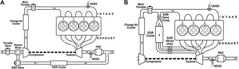
FIGURE 1. Schematic of a (A, left) LP-EGR system and (B, right) HP-EGR system.
The HP-EGR system, on the other hand, is confined entirely within the high-pressure portion of the air system, upstream of the turbine and downstream of the compressor (Figure 1B). As HP-EGR increases, the exhaust back pressure decreases. This system relies on a positive pressure gradient to drive the EGR towards the intake manifold. During stoichiometric operation, when the intake is throttled, the intake manifold pressure can be lower than the exhaust pressure, thus creating a vacuum effect which causes the EGR to flow without the aid of additional backpressure. The HP-EGR system is more widely used in diesel engines due to the simpler layout, less compressor fouling effect and better performance of EGR response than the other EGR systems. With increasing HP-EGR rate at part-load conditions, the exhaust backpressure reduces which leads to reduced pressure difference between the intake and the exhaust. This helps in reducing the pumping losses which is associated with the reduction in fuel consumption (Williams et al., 2017; van Aken et al., 2007).
Southwest Research Institute (SwRI) has continually investigated novel concepts in engine technology through several internal research programs and the High Efficiency Dilute Gasoline Engine (HEDGE™) Consortium. Previous HEDGE-II studies have shown that attempts to matching a single turbocharger or a supercharger to a HEDGE style engine have proven difficult (Joo et al., 2012). When the boosting hardware was matched for low speed operation, the flow range constrains high speed operation. Conversely, when matched for high speed operation, the boosting systems have been unable to produce the high-pressure ratios needed for low speed operation. A HEDGE engine with a HP-EGR and a LP-EGR system was hypothesized to be able to meet the torque curve requirement with a single turbocharger. One of the prior studies (Alger et al., 2005) were carried out on a gasoline fueled engine with varied compression ratios and EGR configurations at several speed and load conditions: HP-EGR with 17.5:1 CR, LP-EGR and HP-EGR systems with external boost at 12.5:1 CR. The study proved that the HEDGE concept had a potential to achieve nearly the same fuel economy performance as a diesel engine equipped to meet the MY2002/2004 emissions levels. Another study (Mao et al., 2015) conducted on a heavy-duty diesel engine suggested that a dual loop EGR system was able to achieve the best brake thermal efficiency (BTE) and emissions. This was because the dual loop EGR system operated with an optimum trade-off between the gross thermal efficiency and the pumping losses and the lowest emissions were related to the proper ignition delay and equivalence ratio. During this study, the HP-EGR system was able to operate at its best when the EGR rate was below 22.5%, hence for the dual loop EGR system, the LP-EGR loop was enabled when the EGR rate exceeded 22.5% and the LP-EGR proportion increased with an increase in the required EGR.
When operating the engine with HP-EGR, it was seen that there was significant backflow through the HP-EGR circuit. As a result of this backflow, the net EGR delivered to the cylinders was lower than commanded. To overcome this problem, a one-way valve was incorporated in the HP-EGR system which helped in preventing this backflow and resulted in a net higher EGR fraction while maintaining reasonable actuator positions. This study documents the approaches taken in configuring the baseline engine to accommodate for the blended EGR systems (HP-EGR and LP-EGR) and a comprehensive evaluation of utilizing the one-way valve to prevent the backflow caused during the HP-EGR operation.
In this project, a KIA G4KH 2.0 L light-duty engine was used to demonstrate blended EGR performance. The specifications of the engine are shown below in Table 1. The production G4KH engine maximum load is 23 bar BMEP and 205 kW.
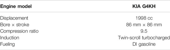
TABLE 1. Engine specifications.
The power density level for this engine places it in the mid-to-high output range, however, maintaining such lofty performance with EGR was not probable. Hence, the goal was to run a constant 20 bar BMEP from 2,000 to 5,000 rpm and produce 85 kW/L at 6,000 rpm (achieved with 17 bar BMEP). A proposed EGR rate of 25% would be run with stoichiometric fueling at all the points but reduced EGR would be tolerated to meet the BMEP target and stabilize the combustion process. A single turbocharger was matched to meet the low-speed torque requirements when running with LP-EGR to preserve the scavenging capabilities. At high speeds, the same turbocharger was projected to be able to meet the high-speed torque requirements when running with HP-EGR. Figure 2 shows the baseline and the proposed torque curve.
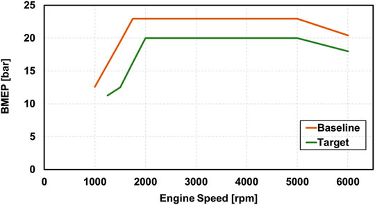
FIGURE 2. Baseline and proposed performance curves.
The engine was installed along with an Engine Control Unit (ECU) provided by Hyundai Motor Company (HMC) that was loaded with a production calibration to conduct all engine run-in operations and for baseline testing of the engine. The engine was verified to match the expected Brake Specific Fuel Consumption (BSFC) at over 50 different operating points. The torque curve up to 6,000 rpm was also verified. Eight specific load-speed operating conditions (shown in Table 2) were used as a basis for future comparisons of the BSFC.
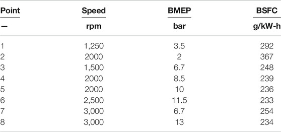
TABLE 2. Measured BSFC at the HEDGE test conditions.
Once the engine was validated on the test stand, the GT-Power model sent by HMC was validated in line with the engine results. The model was then modified to incorporate the HP-EGR system with a set of hot-side and cold-side valves, the LP-EGR system and a suitable turbocharger. Initially, the OEM turbocharger was scaled in the model to show that it could meet the lug curve targets with the Blended EGR configuration. These results were then used to match potential turbochargers to the engine. A scaled GT2056 turbocharger provided by Garrett Turbochargers (formerly Honeywell) was used further in the study.
All the results obtained were at the target 25% EGR operation except for 2,000 rpm and below, where the EGR rate was reduced to 15% to achieve the BMEP target. A rated power of 90 kW/L (vs. the 85 kW/L proposed target) was achieved at the rated power point of 6,000 rpm 18 bar BMEP with 25% EGR.
Figure 3 shows how the two EGR systems combine to meet the total EGR requirement of the engine at full load. At 2,000 rpm, EGR was provided solely by the LP-EGR system. As the turbine inlet pressure increased and bypassing the exhaust through the wastegate was required, the HP-EGR was used. The general EGR control strategy was to use as much HP-EGR as possible while keeping the wastegate open (Figure 4) This is because HP-EGR has lower pumping losses associated with its operation as it used a delta pressure to drive the EGR.

FIGURE 3. Blended EGR from the HP-EGR and LP-EGR systems.

FIGURE 4. Wastegate diameter at full load.
There was a high focus on the compressor performance to identify if the EGR strategy being deployed, drove the compressor into undesirable operating regions, namely choke or surge. Surge is most likely to occur at low-speed and higher load, where the mass flow is low, but the pressure ratio is high. Choke occurs at higher mass flows where the compressor reaches the physical mass flow limit. Figure 5(LEFT) shows the blended EGR operating region on the baseline (stock) compressor (data is proprietary and hence the values of pressure ratio, speed, mass flow and efficiency are hidden). The key take-away from the figure is that the blended EGR operation with the baseline compressor drove it into undesirable operating regions of choke and surge, and so a different compressor (scaled by mass flow rate) was used for this study.
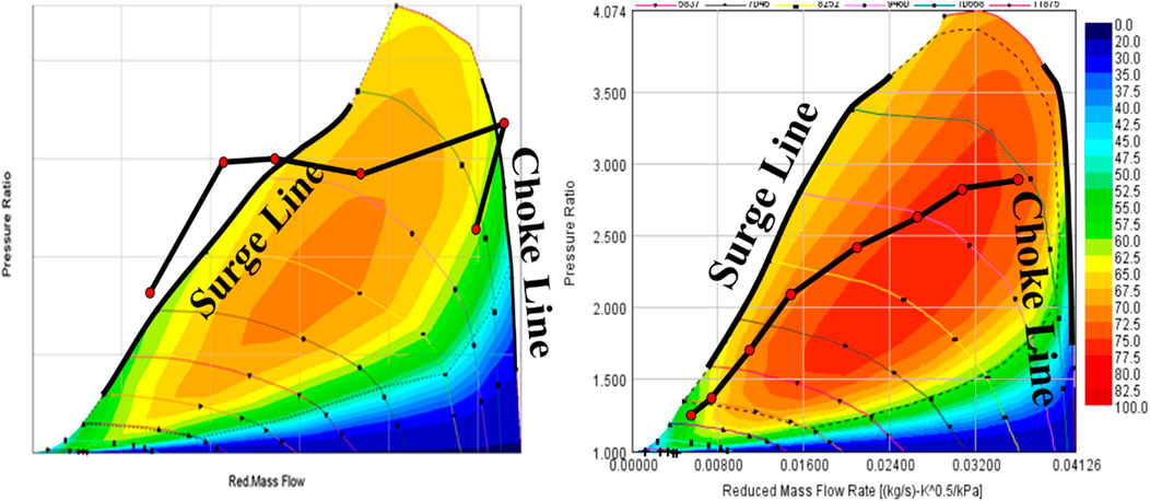
FIGURE 5. Blended EGR operating points on the (LEFT) Baseline/stock compressor map and the (RIGHT) New compressor efficiency map.
The blended EGR strategy allowed a single turbocharger to operate over a wide speed range. At high speeds, HP-EGR reduced the mass flow through the turbocharger, allowing a smaller turbocharger to be used compared to using LP-EGR at high speeds. An LP-EGR strategy at low speeds increased the mass flow through the turbocharger in comparison to HP-EGR. The higher mass flow produced greater expansion work across the turbine resulting in more low speed boost and the compressor operating point shifting towards the right (away from surge). Figure 5(RIGHT) shows the new compressor operating points (Garrett Turbochargers’ scaled model) indicating that the flow does not go into the surge and choke regions as it did with the baseline compressor. This margin would be maintained if the EGR was replaced with fresh air to run at a greater BMEP.
Once baseline testing was conducted and the model was validated, steps were taken to change the configuration to accommodate the blended EGR strategy. The initial part of the step included the installation of the LP-EGR and the HP-EGR circuits (with the valves and coolers). The HP-EGR system consisted of hot side and cold side valves, EGR coolers and a one-way valve. Both sets of valves were independently evaluated in simulations and on the engine and it was found that with the presence the hot-side valves, there was higher mass flow through the turbine which led to more boost and higher loads achievable during the LP-EGR operation. Due to this performance gain, the hot-side valves were chosen in the HP-EGR configuration. The demands from the ignition system increased with the increase in dilution due to EGR. Thus, the stock ignition system was swapped with a prototype BorgWarner Dual Coil Ignition (DCI) system, which uses a Dual Coil Offset (DCO™) technology previously developed by SwRI (Alger et al., 2011). Figure 6 shows the complete schematics of the blended EGR configuration.
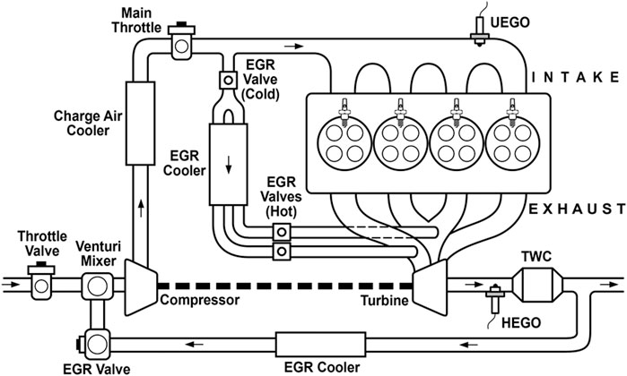
FIGURE 6. Blended EGR configuration.
The production controller used for the initial break-in and validation was not capable of controlling the dual EGR loops and hence the engine was transitioned to a custom, full authority controller based on a National Instruments cRIO (Compact Reconfigurable Input Output). The cRIO was configured to operate the EGR, inlet restriction valves and the DCI system. The inlet restriction valve was used to drive the LP-EGR at low speeds where the intake pressure was higher than the exhaust pressure. With the installation of the blended EGR components, validation of the SwRI controller was performed. The results of this testing were compared with the data collected with the baseline/stock controller (Table 2) to ensure that the engine performance could be repeated over the eight HEDGE points. The resulting difference between the stock and the SwRI controllers, as seen in Figure 7 show that the engine performance matched withing expected tolerances.
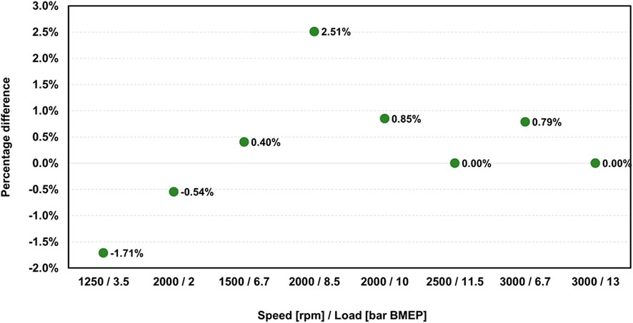
FIGURE 7. BSFC Percentage difference between the baseline (stock) controller and SwRI controller.
The validation of the SwRI controller was followed with further simulation and engine testing for the complete blended EGR system. During the testing, it was observed that there was sufficient backflow of the intake charge through the HP-EGR system. At some of the operating points, this backflow did not permit the flow of EGR into the cylinder. The next section speaks in detail with regards to utilizing a one-way valve to prevent this reverse flow.
As stated earlier, during HP-EGR operation, instantaneous pressure pulsations would drive the intake charge back through the HP-EGR circuit. This backflow generated higher peak mass flow rates through the HP-EGR circuit and limited the maximum HP-EGR amount. At some operating conditions, the pressure difference between the intake and exhaust manifold did not permit HP-EGR flow, and the main throttle had to be closed to create a pressure differential to drive HP-EGR. A one-way valve reduced backflow into the HP-EGR circuit and permitted HP-EGR use where the manifold pressure difference across the engine did not naturally drive HP-EGR. Initial simulations indicated that there were some conditions where backflow was possible (Figure 8). Reverse flow was present when the predicted mass flow was below zero.
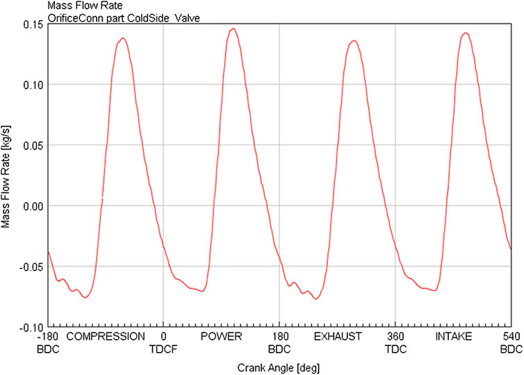
FIGURE 8. HP-EGR mass flow rate indicating backflow.
A one-way valve located at the connection of the HP-EGR circuit to the intake manifold prevents this backflow. The elimination of the backflow should permit a greater HP-EGR flow for a given delta pressure. The one-way valves were modeled in GT-Power as orifices with a reverse discharge coefficient of zero (Figure 9). This model represented the maximum potential of a one-way valve.
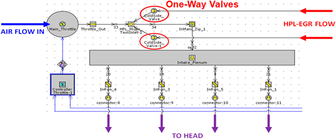
FIGURE 9. One-way Valve modeled in GT-Power.
At 3,000 rpm, 13 bar BMEP and 15% EGR, a higher peak mass flow developed through the HP-EGR circuit without the one-way valve (check valve) as shown in Figure 10. This trend existed at low-speed, low-load and high-speed, high-load conditions as well (Figure 11). The significant back flow at all points suggested the potential expansion of the HP-EGR operation.
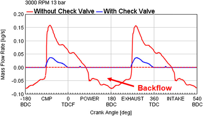
FIGURE 10. Backflow at 3,000 rpm, 13 bar BMEP and 15% EGR.
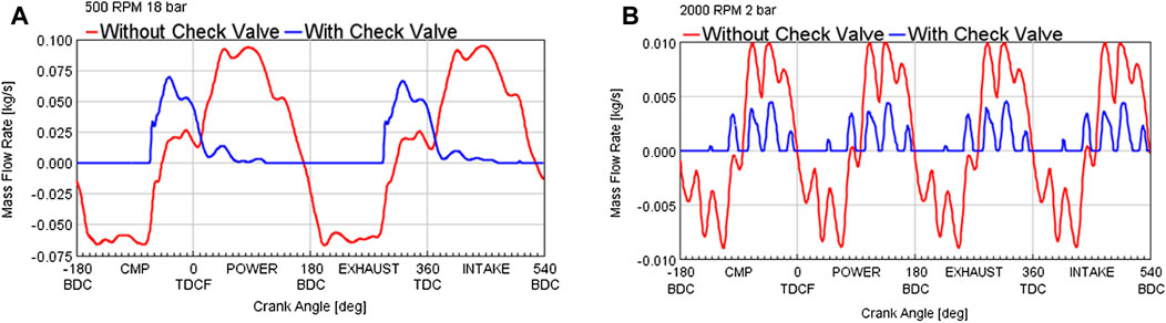
FIGURE 11. One-way valve comparison at (A, left) 2,000 rpm, 2 bar BMEP; (B, right) 4,500 rpm, 18 bar BMEP.
Using a one-way valve in the HP-EGR loop helped in reducing the peak mass flow rate by about 50% at the 2,000 rpm, 2 bar BMEP condition and about a 25% at the 4,500 rpm, 18 bar BMEP condition.
A closer look at the Log P vs. Log V plots (Figure 12) for the above conditions reveals that from the outset, there is no significant difference between the cases with and without the check valve. It must be noted that this study was conducted at largely similar conditions between cases and hence there was no significant difference observed from the Log P vs. Log V plots.
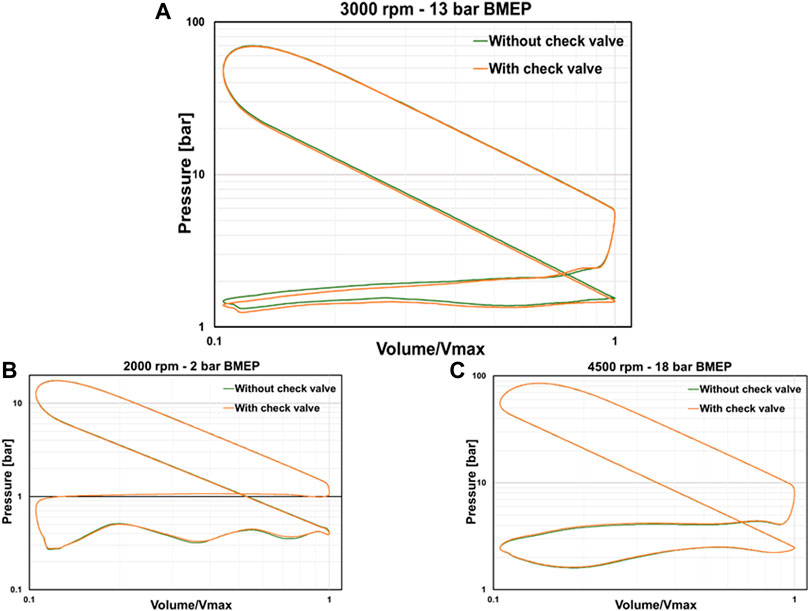
FIGURE 12. Log P vs. Log V comparison with and without check valve at (A) 3,000 rpm, 13 bar BMEP; (B) 2,000 rpm, 2 bar BMEP and (C) 4,500 rpm, 18 bar BMEP.
The simulations showed for more reasonable EGR valve position when the HP-EGR system is operated with the one-way valve as opposed to without a one-way valve. This is largely shown at the 3,000 rpm, 13 bar BMEP conditions where without the one-way valve, a 67% higher actuator position achieves a lower in-cylinder EGR fraction compared with the case with a one-way valve (Table 3).
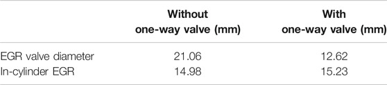
TABLE 3. EGR actuator position and the in-cylinder EGR at 3,000 rpm and 13 bar BMEP.
The greatest reduction in the peak mass flow with the one-way valve and the largest change in the actuator position of the EGR valve was seen at the operating condition of 13 bar BMEP at 3,000 rpm. This substantial reduction in the peak mass flow rate suggests a greater EGR capability at the condition. Hence this operating condition was chosen for further examination. GT-Power and the engine data indicated that the main throttle must be closed to drive the HP-EGR at this condition (Step 1 of Table 4). The one-way valve was introduced (in Step 2 of Table 4) while maintaining the same throttle angle and the simulation predicted an 8% increase in the HP-EGR rate, limited only by the turbochargers ability to produce enough boost to maintain load. Slightly closed throttle is not ideal for operation but is required at some conditions to drive the HP-EGR. Also, the HP-EGR valve was not fully open in Step 2, which suggested the possibility of opening the throttle further. Step 3 of Table 4 maintained the same EGR amount as Step 2, but the throttle was now opened fully. Usable HP-EGR region can be thus expanded and lead to the possibility of more HP-EGR at this condition. For Step 4 of Table 4, the maximum EGR amount was attained at 27%, limited again by boost. A one-way valve was able to nearly double the HP-EGR rate without increasing the backpressure or the PMEP. The PMEP benefit can be realized better near the boundary of the HP-EGR operation and is generally from the increased EGR rate and WOT operation enabled by the one-way valve.
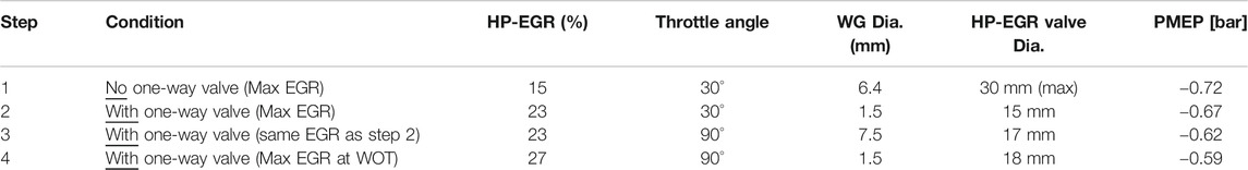
TABLE 4. HP-EGR operation expansion with one-way valve.
The results of the one-way valve on the engine were equally promising. At the 13 bar BMEP at 3,000 rpm condition, they provided for more reasonable actuator positions in terms of the throttle and EGR valves (Table 5).
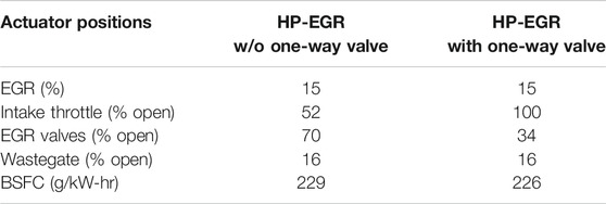
TABLE 5. Actuator positions at 3,000 rpm/13 bar BMEP conditions.
HP-EGR with a one-way valve was also tested at 1,500 rpm and high load condition. Figure 13 shows that without a one-way valve, due to the backflow of exhaust into the HP-EGR system, there is net 0% EGR flowing to the engine. However, using a one-way valve, even at the low-speed and high load condition where HP-EGR is not expected to flow, allows a 16% net EGR flow. This demonstrated the capability of the one-way valve to expand the use of HP-EGR.
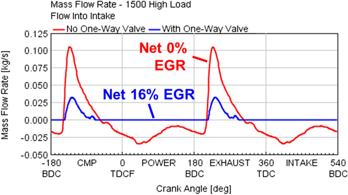
FIGURE 13. EGR flow with the one-way valve at low-speed and high load condition.
With the lower peak mass flow and the higher EGR delivered during the HP-EGR operation with the one-way valve, there is a higher pressure delivered to the turbine. Hence, a smaller turbine can be used to extract the same amount of boost with the one-way valve. A smaller turbine would also be useful in transient operation as it would be able to deliver a faster response resulting in a lower turbo-lag.
In this work, the effects of a one-way valve in the HP-EGR system have been analyzed. While investigating the blended EGR system on a light duty gasoline engine, it was noticed that during the HP-EGR operation, instantaneous pressure pulsations were driving the EGR back through the high-pressure EGR loop. To achieve the desired EGR at a given condition, the engine had to expend energy in the form of pumping work. Various simulation run with a one-way valve on GT-Power indicated its benefit in preventing any backflow through the high-pressure EGR loop which in turn led to the expansion of the HP-EGR operating range. During the simulations, this meant for a much wider throttle positioning which minimized the pumping work and increased the throughput of the HP-EGR system.
Noticing the promising results on simulations, the setup was implemented on an engine. The results from engine testing indicated reasonable actuator position in terms of the EGR valve and the throttle angle. Wider throttle meant that pumping work was significantly reduced. Slightly better BSFC was also observed with the one-way valves in place which was not observed during the simulations. Further, the ability of the one-way valve to expand the amount of EGR at all conditions led to increased pressures to the turbine. Thus, a smaller turbine could be used to generate the same amount of boost to meet the load requirements.
This paper explores the implications of a one-way check valve on the backflow through the HP-EGR system. As noted, during the HP-EGR operation, due to the significant backflow through the HP-EGR loop, there is a higher peak mass flow through the system to achieve a given EGR rate to the cylinder. With the introduction of the one-way valve, the peak flow is reduced to deliver the net EGR rate to the cylinders. What is also observed is that due to the lesser backflow, a more reasonably actuator position can be achieved. The scope of the work was limited to the preliminary usage of the one-way valve on the EGR controllability in a HP-EGR system and checking the viability of the concept. Future publications will include a comprehensive study of the performance improvements with reference to the BSFC and the optimized pumping losses when operating the blended EGR system over the regulatory drive cycles.
The datasets that are presented in this article were approved by the HEDGE members. Addition datasets are proprietary and not readily available. Requests to access the datasets should be directed to Dr. Graham Conway [Z2NvbndheUBzd3JpLm9yZw==].
BD contributed to the GT-Power simulations of the blended EGR system. GC and BD performed the engine experiments and SR contributed to the integrating the controls unit for on engine testing. GH was involved in gathering the results for the literature.
This work has been funded as a part of the HEDGE-IIITM consortium at Southwest Research Institute.
The authors declare that the research was conducted in the absence of any commercial or financial relationships that could be construed as a potential conflict of interest.
Alger, T., Gingrich, J., Mangold, B., and Roberts, C. (2011). A continuous discharge ignition system for EGR limit extension in SI engines. SAE Int. J. Eng. 4 (1), 677–692. doi:10.4271/2011-01-0661
Alger, T., Hanhe, S., Roberts, C., and Ryan, T. (2005). The heavy duty gasoline engine - a multi-cylinder study of a high efficiency, low emission technology. SAE Technical Paper 2005-01-1135. doi:10.4271/2005-01-1135
Joo, S., Alger, T., Chadwell, C., and De Ojeda, W. (2012). A high efficiency, Dilute gasoline engine for the heavy-duty market. SAE Int. J. Eng. 5 (4), 1768–1789. doi:10.4271/2012-01-1979
Jun, J., Song, S., Chun, K., and Lee, K. (2007). Comparison of NOx level and BSFC for HP-EGR and LP-EGR system of heavy-duty diesel engine. SAE Technical Paper 2007-01-3451. doi:10.4271/2007-01-3451
Maiboom, A., Tauzia, X., Shah, S., and Hétet, J. (2010). Experimental study of an LP EGR system on an automotive diesel engine, compared to HP EGR with respect to PM and NOx emissions and specific fuel consumption. SAE Int. J. Eng. 2 (2), 597–610. doi:10.4271/2009-24-0138
Mao, B., Yao, M., Zheng, Z., and Li, Y. (2015). Effects of dual loop EGR on performance and emissions of a diesel engine, SAE Technical Paper 2015-01-0873. doi:10.4271/2015-01-0873
Park, Y., and Bae, C. (2014). Experimental study on the effects of high/low pressure EGR proportion in a passenger car diesel engine. Appl. Energy 133, 308-316. doi:10.1016/j.apenergy.2014.08.003
Torregrosa, A., Olmeda, P., Martin, J., and Degraeuwe, B. (2006). Experiments on the influence of inlet charge and coolant temperature on performance and emissions of a DI diesel engine. Exp. Therm. Fluid Sci. 30 (7), 633–641.
van Aken, M., Willems, F., and de Jong, D. (2007). Appliance of high EGR rates with a short and long route EGR system on a heavy duty diesel engine. SAE Technical Paper 2007-01-0906. doi:10.4271/2007-01-0906
Vitek, O., Macek, J., Polášek, M., and Schmerbeck, S. (2008). Comparison of different EGR solutions. SAE Technical Paper 2008-01-0206. doi:10.4271/2008-01-0206
Williams, D. R., Knutzen, H., Chiera, D., and Hampson, G. J. (2017). EGR and backpressure effects on knock behavior in stoichiometric natural gas EnginesLarge bore engines; fuels. Adv. Combus. Vol. 1. doi:10.1115/icef2017-3669
Keywords: high pressure EGR, low pressure EGR, one-way valves, blended EGR, engine performance
Citation: Handa G, Denton B, Rengarajan S, Chadwell C and Conway G (2021) Utilizing One-Way Valve to Optimize Turbocharger Performance on a Blended EGR Engine. Front. Mech. Eng 7:601397. doi: 10.3389/fmech.2021.601397
Received: 31 August 2020; Accepted: 01 February 2021;
Published: 26 March 2021.
Edited by:
Anand Nageswaran Bharath, Cummins, United StatesReviewed by:
Shakti Saurabh, Cummins, United StatesCopyright © 2021 Handa, Denton, Rengarajan, Chadwell and Conway. This is an open-access article distributed under the terms of the Creative Commons Attribution License (CC BY). The use, distribution or reproduction in other forums is permitted, provided the original author(s) and the copyright owner(s) are credited and that the original publication in this journal is cited, in accordance with accepted academic practice. No use, distribution or reproduction is permitted which does not comply with these terms.
*Correspondence: Graham Conway, Z2NvbndheUBzd3JpLm9yZw==
Disclaimer: All claims expressed in this article are solely those of the authors and do not necessarily represent those of their affiliated organizations, or those of the publisher, the editors and the reviewers. Any product that may be evaluated in this article or claim that may be made by its manufacturer is not guaranteed or endorsed by the publisher.
Research integrity at Frontiers
Learn more about the work of our research integrity team to safeguard the quality of each article we publish.