 Khanh Duc Cung
 Ahmed Abdul Moiz1
 Xiucheng Zhu
 Seong-Young Lee
- 1Southwest Research Institute, San Antonio, TX, United States
- 2Michigan Technological University, Houghton, MI, United States
Advanced combustion systems that utilize different combustion modes and alternative fuels have significantly improved combustion performance and emissions compared to conventional diesel or spark-ignited combustions. As an alternative fuel, dimethyl ether (DME) has been receiving much attention as it runs effectively under low-temperature combustion (LTC) modes such as homogeneous charge compression ignition (HCCI) and reactivity control combustion ignition (RCCI). Under compression-ignition (CI), DME can be injected as liquid fuel into a hot chamber, resulting in a diesel-like spray/combustion characteristic. With its high fuel reactivity and unique chemical formula, DME ignites easily but produces almost smokeless combustion. In the current study, DME spray combustion under several different conditions of ambient temperature (Tamb = 750–1100 K), ambient density (ρamb = 14.8–30 kg/m3), oxygen concentration (O2 = 15–21%), and injection pressure (Pinj = 75–150 MPa) were studied. The results from both experiments (constant-volume combustion vessel) and numerical simulations were used to develop empirical correlations for ignition and lift-off length. Compared to diesel, the established correlation of DME shows a similar Arrhenius-type expression. Sensitivity studies show that Tamb and Pinj have a stronger effect on DME's ignition and combustion than other parameters. Finally, this study provides a simplified conceptual mechanism of DME reacting spray under high reactivity ambient (high Tamb, high O2) and LTC conditions. Finally, this paper discusses engine operating strategies using a non-conventional fuel such as DME with different reactivity and chemical properties.
1 Introduction
Air pollution has been strongly linked to the increasing demand for petroleum. Two primary petroleum-based fuels used in internal combustion engines (ICE) are gasoline and diesel. Reasons to pursue alternative fuels are: 1) to mitigate the dependency on petroleum; 2) to decrease engine-out emissions; and 3) to achieve sustainability via renewable energy resources (Bae and Kim, 2016). Dimethyl ether (DME) is a perfect example among alternative fuels that can, fully or partially, replace diesel in compression-ignition (CI) engine application (Teng et al., 2003; Arcoumanis et al., 2008; Lim and Iida, 2015; Bae and Kim, 2016). As a simple chemical compound (CH3-O-CH3), DME produces nearly smokeless combustion due to its chemical structure having no direct C-C bonds and the high oxygen content of ∼34.8% by mass. DME can be derived from many sources, such as natural gas, biomass, waste, and agriculture products. The well-to-wheel (WTW) CO2 emissions (from production to combustion) of DME derived from bio-feedstock are nearly five times less than that of diesel fuel. DME is in the liquid phase at 530 kPa and 298 K. Hence, it can be used as fuel for CI application (Teng et al., 2002). Cetane number (CN) is considered a primary factor in determining DME application for CI engines. The higher CN of DME (>55) than diesel (40–50) allows for better ignition quality, which is a primary factor in determining the application of DME in the CI engine.
Studies (Semelsberger et al., 2006; Arcoumanis et al., 2008; Park and Lee, 2014) have demonstrated that the remaining challenges in developing DME fuel injection system applications are connected with unfavorable fuel properties such as low viscosity (0.12–0.15 kg/ms) and high compressibility (four to six times higher compression work than that of diesel). The use of lubricity additives on fuel can prevent potential damage and wear to moving and rotating parts (i.e., fuel pump, injector plunger, and needle) during injection events. The high compressibility of DME also requires more considerable compression work for a high-pressure injection pump. The lower density (660 kg/m3) and heating value (28.43 MJ/kg) of DME can be accommodated by a larger injected fuel volume to achieve the same amount of energy compared to diesel fuel (ρ = 800–840 kg/m3, LHV = 42.5 MJ/kg). For example, an injection duration of about 37% longer than that of diesel fuel can provide a similar energy amount. Regardless of the challenges in developing the DME fuel injection system, DME remains a competitive alternative fuel to diesel fuel in CI applications due to its availability from biomass resources, resulting in environmentally friendly combustion with superior ignition propensity and the ultra-low emissions of soot. Hence, the spray and combustion of DME should be studied further to understand the mechanism of ignition and flame development processes.
The conceptual mechanism of diesel combustion (Dec 1997) involves mixing fuel and air vigorously to form a combustible mixture before the autoignition event. Ignition delay (ID) affects both physical (atomization, vaporization, mixing) and chemical processes (Chung, 2006). The highly exothermic reaction (during pre-ignition) is followed by a premixed combustion phase (Glassman et al., 2014). Auto-ignition is then followed by a quasi-steady flame during the injection. The diffusion flame remains at a particular location downstream away from the nozzle tip, known as lift-off length (LOL) (Dec and Espey, 1998). A longer LOL indicates a higher degree of premixed combustion that often results in leaner combustion downstream. Lean combustion is also associated with lower soot formation. In diesel combustion, longer LOL can be achieved by increasing injection pressure, a high dilution level, or lower ambient density, as shown in the numerical study by Cung et al. (2018). A larger nozzle diameter also produces long spray penetration overall, including a longer LOL. Figure 1 compares the LOL of DME and diesel reacting spray, which shows high-temperature chemiluminescence imaging of excited-stated OH*. This OH* chemiluminescence has been used as a marker for LOL location (upstream regions where soot has not yet formed) because it is a significant source of light emissions at 310 nm (Higgins et al., 2000). DME has a shorter LOL than diesel under the same ambient conditions. The injector conditions (injection pressure and nozzle size) are also the same. The combustion process of DME is demonstrated from previous CFD simulation results in Figure 1B,C concerning spatial and temporal manners (Cung et al., 2016b). The ambient condition includes 18% O2 concentration, an ambient temperature of 900 K, and an ambient density of 14.8 kg/m3. Spray visualization was captured from an experiment using a single-hole injector with a nozzle diameter of 180 µm under an injection pressure of 75 MPa.
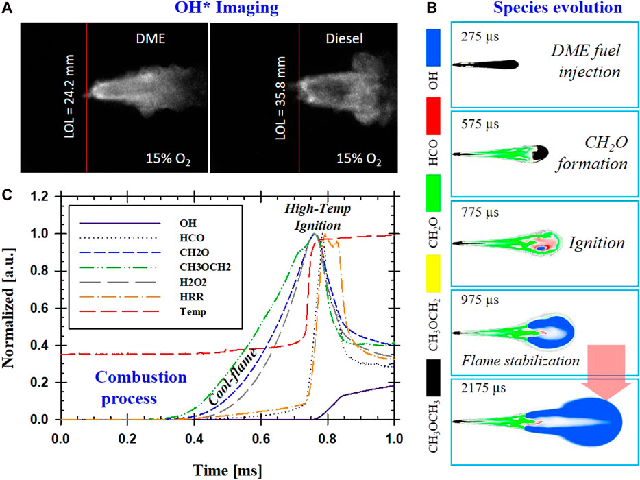
FIGURE 1. (A) Example of OH* chemiluminescence images of DME and Diesel flame; (B) CFD time-elapsed evolution of selected species in DME reacting spray; (C) Temporal formation of key species in DME reacting spray.
First, the formations of CH2O and CH3OCH2 almost overlap spatially. This can be explained by the fact that DME reaction pathway analysis with methoxymethyl decomposes into formaldehyde via beta-scission CH3OCH2 ⇔ CH2O+ CH3, which is the principal source of formaldehyde (Wang et al., 2009). The formation of critical species in DME spray combustion is similar to that of diesel. First, intermediate species of formaldehyde (CH2O) are formed during low-temperature combustion or cool-flame stage near nozzle before the first-stage ignition event. This is followed by the second-stage ignition of high-temperature fuel-rich combustion with OH* radical downstream, marking the beginning of the fuel oxidation process. While CH2O is formed during the first-stage ignition where the temperature is low (small temperature rise shortly after 0.4 ms), H2O2 is a crucial species that decreases during the second-stage of ignition with a significant temperature rise near 0.75 ms. Formyl radicals (HCO) located between CH2O and OH imply a transition between first-stage and second-stage ignition processes. The formation of HCO follows closely with the HRR profile, which would make HCO an ideal marker for cool-flame. However, its concentration levels are extremely too low to be captured experimentally. In diesel combustion, HCO was also described as key species that marks the second-stage ignition followed by the oxidation of unburned hydrocarbon (UHC) species (Musculus et al., 2013). The temporal profile of CH2O planar laser-induced fluorescence (PLIF) can also indicate a cool-flame process that leads to the start of the first-stage ignition. It was shown that ignition could be defined by the early depletion of CH2O (Cung et al., 2017). CFD simulation also showed the importance of the correlation of CH2O and ignition under LTC conditions (low levels of oxygen concentration). Under this low flame temperature, it is difficult to detect early stage ignition by temperature rise. The numerical model shows that the depletion of CH2O should be used as a primary marker for DME's ignition process. The initial formation of CH2O indicates the start of the first-stage ignition. The depletion of CH2O marks second-stage ignition with a significant temperature rise where OH* is typically present.
It is well-known that LOL is a critical factor because it provides spatial information on fuel jet extent. Longer LOL usually means more entrainment of fresh charge into spray jet, which is subjective to lean combustion, hence the lower formation of soot (Pickett and Siebers, 2004; Pickett and Siebers, 2006). Both ID and LOL are affected by initial ambient conditions (temperature, pressure, dilution) or fuel delivery scheme (injection pressure, duration, nozzle size, etc.) (Pickett et al., 2006). Any change in these parameters would alter the physical and chemical process that results in early or late ignition, simultaneously changing the LOL. Flame propagation is mainly driven by premixed-stoichiometric combustion at the atmospheric condition that moves upstream toward reactants. Meanwhile, high-temperature auto-ignition in the lifted spray combustion experiment was seen earlier in the upstream region, separated from the high-temperature formed in flame front (Pickett et al., 2005). Many pieces of evidence have shown that factors such as high-pressure, temperature, and ignition quality are essential to flame stabilization (Higgins et al., 2000; Higgins and Siebers, 2001; Siebers and Higgins, 2001; Pickett et al., 2005; Pickett et al., 2009). Using data from constant-volume combustion vessel experiments, Siebers et al. (Siebers and Higgins, 2001; Siebers et al., 2002) developed an empirical power-law relationship for the LOL of diesel spray. The correlation includes several parameters, such as ambient temperature (Tamb), ambient gas density (ρamb), and injection pressure (as described by jet velocity, uth).
Nozzle geometry such as nozzle diameter or nozzle shape could also affect spray development and fuel-air ratio, which can contribute to the determination of LOL. A larger nozzle diameter often results in longer LOL and vice versa (Pickett and Siebers, 2005; Cung et al., 2018). Nozzle with a smaller diameter can promote air entrainment in a diesel spray, leading to low soot emissions. As experimentally and numerically shown, a nozzle diameter of 50 µm or smaller can eliminate soot almost wholly. However, the effect of the nozzle diameter is not included in the current study. Similarly, the influence of the ambient conditions such as temperature, pressure, and density composition and consideration of jet velocity were also introduced to determine ID with the Arrhenius equation below (Pickett et al., 2005).
with k is pre-exponential constant, A is also a constant (Arrhenius temperature) that accounts for global activation energy (Ea) and universal gas constant (Ru), Ea/Ru. The exponential terms (a, b, and c) usually have negative values that indicate the inverse law of decreasing ignition delay with an increase in ambient density, spray velocity, or oxygen concentration. An increase in temperature also shortens ignition delay.
This paper investigates the effect of various ambient conditions and injection pressures on the ignition and flame stabilization of DME reacting spray. Experiments were performed in an optically accessible combustion vessel. LOL was obtained from OH* chemiluminescence visualization during the quasi-steady state period of the spray. The location of the initial flame kernel was also captured from high-speed flame natural luminosity imaging. Ignition delay was determined from a high-sensitivity photodiode signal. These experiments were used to establish empirical equations for LOL and the ID of DME reacting spray similar to Eq. 1 and Eq. 2, respectively. Additional numerical models were also presented to gain a more in-depth understanding of DME spray combustion's ignition and flame stabilization processes.
2 Experimental and Numerical Approach
2.1 Experimental Setup and Data Analysis
A spray combustion experiment was performed using a similar combustion vessel facility and fuel delivery system, as in a previous study by Cung et al. (2016a). All testing was evaluated using a single-hole injector (Do = 180 µm). The test conditions are summarized in Table 1. The baseline condition was 900 K, 18% O2, 75 MPa, and 14.8 kg/m3. The wide range of testing conditions provides an extensive dataset to develop empirical equations for LOL and ID. Under low temperature (Tamb < 750 K) and low oxygen concentration (<15% O2) conditions, long ID and long LOL were expected. These extreme conditions could be challenging to capture by the empirical model precisely. Moreover, it is challenging to perform spray experiments under these conditions because combustion vessel geometry would not accommodate a flame with a longer LOL.
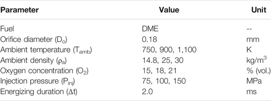
TABLE 1. Summary of tested conditions.
Details of optical diagnostics and data analysis are given in Figure 2A, which shows the arrangement of current optical diagnostics. OH* chemiluminescence was captured using an intensified CCD camera (DiCam Pro) with a 310 nm bandpass filter with 20 nm FWHM coupled with a UV lens (UV-MICRO-APO, 105 mm, f#/4). This filter has been used in several other studies (Higgins and Siebers, 2001; Pickett et al., 2005) to successfully capture the flame structure formed by highly exothermic reactions that release OH* chemiluminescence. A long exposure time of 1.0 ms was used to obtain a time-averaged value of LOL. The OH* image was taken only during periods when the flame was stabilized.
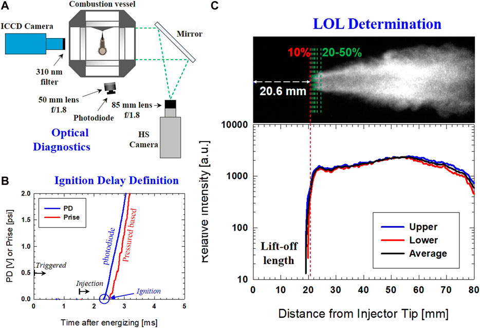
FIGURE 2. (A) Optical setup for OH* chemiluminescence imaging, photodiode signal, and HS natural luminosity; (B) Ignition delay determination by pressure rise and photodiode signal; (C) Lift-off length determination from OH* chemiluminescence imaging.
On the other hand, high-speed (HS) imaging of natural combustion luminosity was set up simultaneously to capture the entire ignition and combustion processes. The HS camera setup includes an 85-mm lens, f#1.8 with 40,000 fps with an exposure time of 24.3 µs Mie-scattering imaging was used for the determination of the start of injection (SOI). SOI was used in data analysis to calculate ID, which is the time difference between actual fuel injection and ignition. Ignition was determined by a high-sensitivity photodiode (Thorlabs DET36A) with a fast response of 1.0 ns. Note that liquid scattering, if any, was not detected by the photodiode; hence it did not affect interpretation of the real ignition event.
There are several ways to obtain an ID in the current experiment: 1) pressure rise in the combustion vessel; 2) HS imaging of combustion luminosity; and 3) photodiode. While the pressure-based approach has been used widely to obtain an ID for diesel combustion, signal filtering was needed to eliminate the noise picked up by the pressure transducer. This adds several uncertainties to extract actual pressure rise due to initial chemical reactions that lead to ignition. Secondly, the HS image offers spatial information about ignition. Still, the substantial exposure time of the HS camera as compared to reaction time is not ideal for providing fair temporal resolution. Therefore, it was decided to use a fast-response signal from photodiode for determining the start of ignition. Figure 2B demonstrates an example of ID obtained by photodiode and pressure rise. The ID predicted by pressure measurement is longer (by ∼ +250 µs).
As shown in Figure 2C, LOL from the OH* image was determined using the following procedure. First, the noise was removed by background subtraction. Intensity along the spray axis (upper and lower of spray centerline) was then extracted and used to obtain profiles, as shown in Figure 2C (lower graph). This resulted in an average profile with a similar "knee" type profile, identical to diesel’s LOL study (Higgins and Siebers, 2001). Among the threshold choices (up to 50%), the 10% peak intensity threshold best represented the LOL for all tested conditions. A similar selection of 8% peak intensity was used to determine LOL under diesel spray combustion (Siebers et al., 2002). The slightly higher threshold could be due to weaker combustion intensity in the DME flame than that of diesel. Nonetheless, the threshold selection shows a minimum effect on LOL determination of less than 2.5% increase in LOL for threshold up to 20%. This is due to the steep increase in the relative intensity "knee" profile, which creates an insignificant change in the determination of LOL by different threshold values.
2.2 Numerical Model
The current numerical approach involves several different models, from a simple closed-reactor model for calculating homogeneous ignition delay to 3D Computational Fluid Dynamics (CFD) spray modeling under different ambient conditions. CONVERGE (Richards et al., 2013) was selected as the CFD simulation tool. It is capable of using adaptive mesh refinement (AMR) to automatically generate a grid-based on the sub-grid gradients of specific parameters, in this case, temperature and velocity. The finest grid was 0.125 mm, with a base grid size of 2 mm. The selected grid size was considered to be appropriate and robust for validating both non-reacting and reacting spray, as suggested by Senecal et al. (Senecal et al., 2013) for the currently selected Reynolds-Average Navier-Stokes (RANS) Re-normalization Group (RNG) k-ε turbulence model. A Lagrangian spray "blob" injection model of Reitz and Diwakar (Reitz and Diwakar, 1987) with the subsequent break-up and atomization model of Kelvin-Helmholtz and Rayleigh-Taylor (KH-RT) (Beale and Reitz, 1999) with no break-up length were used in the simulation.
The No Time Counter (NTC) collision method of Schmidt and Rutland (Schmidt and Rutland, 2000) was also included in the simulation to model droplet collision with a linear increase in computational cost at a higher number of spray parcels. The SAGE detailed chemistry solver (Senecal et al., 2003), a well-mixed reactor-based model running on the CHEMKIN-format of chemical kinetic inputs, was used with the consideration of all species and reactions. This CFD configuration was validated with liquid and spray penetration with an excellent agreement in previous work (Cung, 2015). The same CFD configuration was used in other work (Cung et al., 2017) to study the relationship between intermediate species (formaldehyde) and the ignition process in DME reacting spray. Validation of liquid and vapor penetration was performed under non-reacting spray conditions in previous work (Cung, 2015) before the simulation of a reacting spray.
All the simulations used a reduced mechanism for DME (45 species, 249 reactions) (Cung et al., 2015), which was developed from a detailed mechanism (260 species and 1,039 reactions) (Cung et al., 2013a). The reducing mechanism method is based on a direct relation graph with error propagation (DRGEP) using Reaction Workbench utility (ReactionWorkbench, 2013). The reduced mechanism contains important DME reaction species, soot precursor acetylene (C2H2), soot indicators including benzene and pyrene (C6H6, C16H10), and the GRI-Mech 3.0 NOX formation. Ignition delay was calculated using the current mechanism and compared with other published mechanisms developed by LLNL (Curran et al., 2000; Fischer et al., 2000) and UConn (Bhagatwala et al., 2015) as well as experimental data by Pfahl et al. (Pfahl et al., 1996). Figure 3 shows the results for two different levels of ambient pressure, 13 and 40 bar.
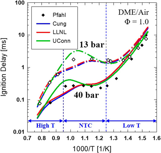
FIGURE 3. Comparison of computed ignition delay for stoichiometric DME/air reaction using different chemical kinetic mechanisms at an initial pressure of 13 and 40 bar over an ambient temperature range of 650–1300 K.
At ambient pressure of 40 bar, it can be seen that the low-temperature region starts at 800 K or lower. The high-temperature ignition region occurs with a temperature of 1050 K or higher. The Negative Temperature Coefficient (NTC) region is 800 K and 1050 K with mildly shortened ID as temperature decreases. The pressure range (∼40 bar) is also relevant to the current spray experiment's ambient pressure, as mentioned in Table 1. In this study, a closed-reactor model was also used to calculate DME ignition under different ambient temperatures and oxygen concentrations relevant to a spray experiment in a constant volume combustion vessel. This provides a comparison between ignition from a homogeneous mixture and premixed combustion from a reacting spray.
The present study also used a simplified reacting spray model to study temperature and equivalence ratio mixture profiles along the spray axis. The spray model, namely, the two-stage Lagrangian (TSL) model, was developed by Broadwell et al. (Broadwell and Lutz, 1998) and has been used in several works of literature for studying mixture formation and emissions (Han et al., 1999; Pickett et al., 2005; Cung et al., 2013b) under diesel-like conditions. The TSL model can simulate the mixing phenomenon of spray by using two-stages (or two reactors) representing flame-core and flame-sheet regions. The model can couple with detailed chemical kinetics with very low demand for a computational resource while having the ability to input the essential features of a turbulent gaseous-jet diffusion flame such as nozzle geometry, injection pressure, fuel-air mixing. Besides the lifted flame model, the mixing model in TSL can provide useful insights on the auto-ignition of the spray as it mixes fuel and hot ambient gas until the combustible condition for auto-ignition is indicated by an increase in temperature. This approach can be used to study different stages of ignition, especially the cool-flame period where intermediate species such as formaldehyde (CH2O) are abundant (Khanh Cung and Seong-young, 2015).
3 Results and Discussion
3.1 Empirical DME Ignition Model
Experimental ignition delay (ID) data from the different conditions shown in Table 1 were used to fit into an Arrhenius type in Eq. 3, where k = 0.033, A = 4,034.201 K, Tamb is the ambient temperature (K), ρamb is ambient density (kg/m3), uth is the theoretical velocity of the fuel at the nozzle outlet (m/s), and O2 is ambient oxygen concentration (%).
The regression equation has the coefficient of determination (R2) of 93.4%. A higher accuracy statistical model can be achieved with more repeated test points at each condition. Moreover, smaller changes in the value of each parameter can provide extensive empirical model data. The current study considers at least three repeats for each condition. Low prediction of ID was expected for the conditions of very low temperature (<750 K) and highly diluted (<12% O2). This is because combustion becomes more unstable at LTC conditions. A combustion with a long ID could occur near-wall due to the limited geometry of the combustion vessel. Ignition and combustion are, therefore, no longer considered a free-jet phenomenon. Moreover, spray/flame recirculation could affect the boundary conditions (temperature and mixture composition of products) upstream, affecting the LOL (Pickett and López, 2005).
Using the empirical relationship of ID with other parameters as shown in Eq. 3, the ID of DME reacting spray was calculated for different ambient temperatures and oxygen concentrations, which produce the T-O2 mapping for ID. The injection pressure and ambient density were kept constant at 75 MPa and 14.8 kg/m3, respectively. The result is shown in Figure 4A with constant ignition lines from the empirical equation. The grayscale contour in Figure 4A is the calculation of ID using a closed-reactor as a function of ambient temperature and oxygen for the same equivalence ratio (Φ) of 1.65 and ambient pressure of 3.77 MPa. A Φ of 1.65 was selected because a previous study (Cung et al., 2016a) suggested that the ignition of DME generally occurs at this equivalence ratio value under a wide range of O2 concentrations.
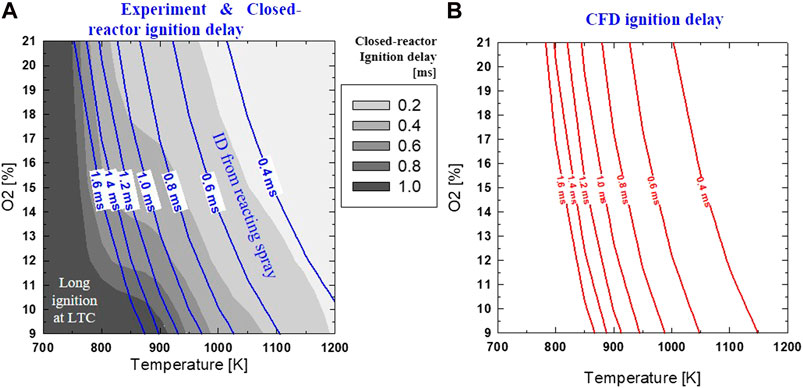
FIGURE 4. Ignition delay over different Tamb and O2 predicted by: (A) homogeneous constant-pressure reactor (gray scale) simulation at ϕ = 1.65 and Pamb = 3.77 MPa; and spray experiment of 900K, 18% O2, 75 MPa, 14.8 kg/m3 (blue solid lines); (B) CFD simulation (same condition as experiment) with ID defined by CH2O profile.
Figure 4A shows that both experimental based and closed reactor ignition delays have a similar trend of a longer ID, as ambient temperature or oxygen concentration is reduced. For the same temperature and oxygen concentration, ID from the experimentally based calculation is longer than that of a closed-reactor. This is because the autoignition phenomenon involves both physical delay (fuel atomization, evaporation, fuel-air mixing) and chemical delay (e.g., intermediate reactions before premixed ignition). On the other hand, the closed-reactor model neglects any realistic physical mixing effect between spray and the surrounding gas, changing the initial conditions, including temperature and mixture composition. As shown with closed-reactor calculation, long ID (>1.0 ms) is expected with Tamb < 800 K. It was interesting to see that ID from spray experiment has a similar trend with closed-reactor prediction under higher ambient temperature (approximately 1000 K or higher). This could be due to the highly reactive combustion of DME in high-temperature conditions overcoming the significance of other factors (as listed in Eq. 3), including mixing, oxygen concentration.
Under low-to-intermediate temperatures (800–900 K) the kinetic model shows NTC-like ID profiles and iso-ignition delay lines become less steep. Here, ID becomes less sensitive to the change in temperature than other regions of the T-O2 map. However, experimental based ID does not show an NTC-like ignition profile within this temperature range. The ID in spray experiment under this temperature range may be long enough that intermediate species produced from low-temperature heat release (LTHR) reactions promote ignition, therefore, offsets the significance of the NTC-like effect. For example, an iso-ignition delay line from the experiment of 1.0 ms is maintained under a (negative) proportional relationship between O2 and temperature: ↑Tamb and ↓O2 or ↓Tamb and ↑O2. Meanwhile, the grayscale of ID from a closed-reactor (under the same range with experimental iso-ignition delay of 1.0 ms: 850–900 K, and 17–18% O2) shows that a faster rate of temperature increase is required to keep a constant ID.
The ignition delay from the CFD simulation in a spray experiment indicates a similar profile, as shown in Figure 4B. Both experiments and CFD results show that ID is affected more by Tamb than O2 concentration. This indicates that DME combustion can withstand high levels of EGR or low O2 concentration. An ignition delay of approximately 1.0 ms or less can be achieved with an ambient temperature of at least 850 K over a wide range of O2 levels (9–21%). A more detailed comparison of the ignition delay between the experiment and CFD simulation is provided in Figure 5.
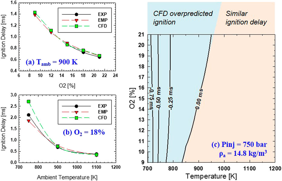
FIGURE 5. (A) Comparison of ignition delay by experiment (EXP), empirical equation (EMP), and CFD at 900 K, 14.8 kg/m3, and 75 MPa for different levels of O2; (B) Similar comparison for the various ambient temperature at 14.8 kg/m3, 75 MPa, 18% O2; (C) Difference of ignition delay between EXP and CFD over different Tamb and O2 at same condition of 14.8 kg/m3 and 75 MPa.
The effect of oxygen concentration and ambient temperature are shown separately in Figure 5A and Figure 5B, respectively. It can be seen that under the same ambient temperature (Tamb = 900 K), the ID displays a very similar trend between experiment and simulation. Current CFD slightly overpredicts experimental ID, especially with O2 of 15% or lower. However, under the same O2 of 18%, as shown in Figure 5B, the difference in ID from experiment and CFD becomes more evident at low ambient temperature. This could be due to the limited validation temperature range of the current DME mechanism for the ignition process under low ambient temperatures (750 K or below) (Cung et al., 2015).
The difference in ID between CFD and the experiment is shown in Figure 5C. The difference is calculated by subtracting the ID from CFD to that of the experiment. Two regions of the T-O2 map are highlighted: a high-temperature region with very similar ID, low-temperature region (below ∼850K) with increasing difference in ID as ambient temperature decreases. Under low ambient temperature (below 750K), there is almost no effect of O2 concentration on the ignition delay difference between experiment and CFD. It is fascinating to see that the zero-difference ID line closely aligns with NTC or deflection points in closed-reactor contour, as seen in Figure 4. This could be explained by a minimum change in ID within the NTC region compared to other high and low-temperature regions where ignition delay changes more proportional to temperature change. Showing an ambient temperature range from 830 to 950 K, Figure 5 shows that CFD over-then under-predicts the ignition delay compared to the spray experiment as O2 decreases.
3.2 Empirical DME Lift-Off Length Model
The power-law relationship of lift-off length, H [mm] in DME reacting spray is expressed in Eq. 4 (R2 = 96.3%) with C = 4.6 × 10⁸, Tamb as ambient temperature (K) ρamb is ambient density (kg/m3), uth is the theoretical velocity (discharge coefficient or Cd of 1.0) of the fuel at the nozzle outlet (m/s), and O2 is ambient oxygen concentration (%). Shorter LOL results were obtained from higher Tamb, higher ρamb, lower injection pressure, or higher O2 concentration. This is a known trend in LOL for diesel reacting spray (Pickett et al., 2005).
Using the established equation above for LOL, the effects of ambient temperature and oxygen concentration were first investigated. The LOL profile in T-O2 mapping is shown in Figure 6. Injection pressure and ambient density were kept constant at 75 MPa and 14.8 kg/m3, respectively. Selected OH* chemiluminescence images of tested conditions also visualize LOL and the general flame structure at each condition, as numbered.
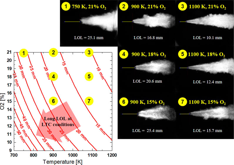
FIGURE 6. Calculated LOL with different Tamb and O2 at similar Pinj = 75 MPa, ρ = 14.8 kg/m3. Example OH* image shown for each corresponding (numbered) condition of Tamb and O2.
For the conditions of 1-2-3, at the same O2 concentration of 21%, LOL decreases as ambient temperature increases. Strong signal intensity of flame in OH* (both in the periphery and central regions of the flame) image at higher ambient temperature conditions indicates a strong fuel oxidation reaction. It can also be seen that the combustion is delayed later at low ambient temperature, allowing the flame to reach further downstream while also expands radially toward the combustion vessel wall. The interaction of flame and a flat wall has been shown to possibly further increase soot oxidation due to increased mixing with ambient air during wall impingement. Soot reduction could also occur during flame-wall interaction due to the thermal effects of the cooling jet, which slow the soot formation process (Pickett and López, 2005).
Conditions 2-4-6 and 3-5-7 show the effect of dilution or different oxygen levels on LOL and flame structure at the same ambient temperature of 900K and 1100 K, respectively. First, LOL is inversely proportional to O2 concentration in the ambient. Flame LOL increases by ∼9 mm (under 900 K) and ∼6 mm (under 1100 K) as O2 decreases from 21 to 15%. The reaction within flame central appears to be weaker, as shown in the OH* images at lower O2 concentration, especially for an ambient temperature of 900 K. This is explained by lower flame temperature as dilution level increases, which results in lower net generation of OH*. Under condition 6, the lack of OH* production is continuously shown at the flame core throughout the expansion of flame as the jet moves further downstream. At higher ambient temperature conditions (3-5-7), OH* forms less at the flame core as O2 decreases. This is because the flame combusts closer to the injector nozzle size.
The contour plot shows that LOL becomes longer toward the lower-left corner of the T-O2 map, where both oxygen concentration and ambient temperature are low (LTC condition). Under the considering range of ambient temperature and oxygen concentration, it is shown that the ambient temperature has more impact on the location of LOL (similar to the effect on ID). The LOL sensitivity with both O2 and Tamb decreases as either of these parameters increases (toward the upper-right of the T-O2 map). For example, at high ambient temperature (1100 K), oxygen concentration needs to be reduced from 21% to 13% to reduce LOL by 5 mm (10–15 mm). While at low ambient temperature (750 K), the oxygen concentration is only required to reduce from 21 to 17% to increase the LOL by 5 mm (25 mm–30 mm). This analogy can be made for the effect of ambient temperature at a similar oxygen concentration. As shown in the T-O2 mapping, similar LOL can be seen for conditions of 1 vs. 6 and conditions of 2 vs. 7. This is an example of the competing effects of Tamb and O2 that results in an insignificant change in LOL. For conditions 1 vs. 6 with LOL of approximately 25 mm, the higher ambient temperature case (900 K) shows a more aggressive ignition event, as demonstrated by a strong signal near the LOL location at the flame periphery. But the dilution effect is clearly shown in condition 6 with a lack of OH* at the flame core as compared to more OH* production in the flame core at condition 1. As the ambient temperature increases in conditions 2 and 7, the difference in the OH* intensity near LOL is the opposite, with a stronger signal for condition 2, even though the temperature is lower than condition 7. In summary, the effect of ambient temperature and oxygen concentration indicates that the same oxygen concentration and higher temperature shortens LOL and that the flame periphery structure is more defined.
On the other hand, a higher dilution or lower oxygen concentration shows a cooler flame core with the lack of OH* formation for the same temperature. At high-temperature condition, the contrast between flame periphery and flame central become more noticeable, especially near the location of LOL. Further downstream of the flame, a low oxygen concentration still shows less OH* concentration near the flame core, as seen in condition 6. However, more reaction occurs in the flame core at a higher temperature, and OH* radicals appear earlier between LOL and most downstream of the flame.
It is interesting to see that LOL can be held constant with different combinations of Tamb and O2. For example, when LOL at baseline condition is approximately 20 mm, O2 can vary from 21 to 9%, with Tamb increased from 830 to 1125 K. As it turns out, ID is then reduced from 1.0 ms to 0.7 ms. This indicates that while LOL remains constant, the initial ignition location may not stay the same. Shorter ID suggests that the auto-ignition event most likely occurs closer to the injector tip. Although both ID and LOL are more sensitive to Tamb than O2, there is no definite correlation between ID and LOL (plot of LOL vs. ID can be found in the supplementary material for both diesel and DME). This was also suggested in diesel spray combustion study in Ref. (Pickett et al., 2005). They found that the first stage ignition phenomenon upstream, also known as cool-flame, is more critical on the mechanism of flame stabilization than second-stage, high-temperature combustion. This is presumably even more relevant for DME flame as it has higher reactivity and the chemical reaction pathway for fuel oxidation is relatively simple as compared to that of diesel, hence resulting in overall shorter ID (Curran et al., 2000; Fischer et al., 2000; Wang et al., 2009). Additionally, the fast evaporation of DME reduces the physical delay between fuel atomization and the gaseous charge of a "readily" combustible composition (Teng et al., 2003; Arcoumanis et al., 2008).
The correlation of injection pressure and ambient density (Pinj—ρamb map) on LOL and ID is shown in Figure 7. The ambient temperature and O2 concentration were kept constant at 900 K and 18%, respectively. It can be seen that constant ID or LOL can be achieved by simultaneously increasing Pinj and ρamb. However, ID and LOL are more driven by ρamb. This is reasonable since higher ρamb is linked with higher ambient pressure, enhancing the fuel’s ignitability. OH* chemiluminescence images of conditions 1–2-3 show the effect ρamb with shorter LOL as ρamb increases. As ρamb increase from 14.8 to 30 kg/m3, ID decreases by ∼0.3 ms, and LOL decreases by ∼10 mm. Spray penetration is also expected to reduce as ρamb increases, with more air entrainment at higher ρamb results in a narrow flame structure. Further spray penetration at lower ρamb results in a more radially expansive flame, as shown in a larger area of high-temperature combustion region.
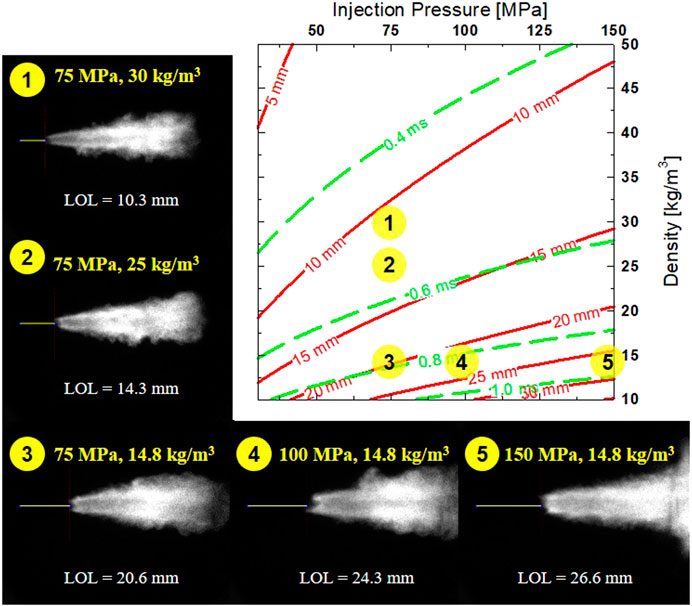
FIGURE 7. Calculated LOL with different Pinj and ρamb at similar Tamb = 900 K, O2 = 18%. Example OH* image shown for each corresponding (numbered) condition of Pinj and ρamb.
Both ID and LOL increase at higher Pinj. In diesel combustion, higher Pinj slightly reduces ignition delay (Payri et al., 2016). While higher Pinj typically reduces physical delay by improved atomization, but could also lead to overmixed fuel-air. This would result in a lower equivalence ratio that leads to a longer ID. Perhaps, this effect is more pronounced in a highly volatile fuel such as DME. Example OH* chemiluminescence images of condition 3-4-5 shows that LOL increases by ∼6 mm while ID increases by only ∼0.1 ms as Pinj are increased from 75 to 150 MPa. As expected, higher velocity in the spray at higher Pinj moves the combustion zone farther downstream (Pickett et al., 2005; Pickett et al., 2006). Faster spray penetration is typically seen with higher Pinj, which results in more combustion occurring downstream, near the combustion vessel wall. Spray-wall interaction can be seen in condition 5, as flame spreads out radially during flat wall impingement. Accumulation of OH*, as seen in the chemiluminescence image at high Pinj (150 MPa), suggests a potential pathway to increasing soot/fuel oxidation with more abundant hydroxyl radicals (OH) via spray-wall interaction.
3.3 Flame Structure and Ignition Location
3.3.1 Effect of Ambient Temperature and Oxygen
Further investigation on the impact of Tamb and O2 on the ignition mechanism of a DME flame is shown in Figure 8. Experimental conditions from high Tamb–low O2 to low Tamb–high O2 are selected for the comparison of the competing effect of these parameters on the ignition of DME reacting spray. These are the same conditions of 7, 4, and 1, as shown in Figure 6. The experimental result is shown in Figure 8A with similar injection pressure (Pinj = 75 MPa) and ambient density (ρamb = 14.8 kg/m3). Here, lift-off length and high-temperature flame structure are shown in OH* chemiluminescence image, while the location of the initial flame kernel (high-temperature ignition) is shown in instantaneous HS images of DME natural flame luminosity. The values of LOL and ID (from the HS image) are both given in the figure. The numerical results of spray-core equivalence ratio and temperature from the TSL mixing model are shown in Figure 8B, with each Tamb and O2 combination set up to have a constant LOL of 20.6 mm.
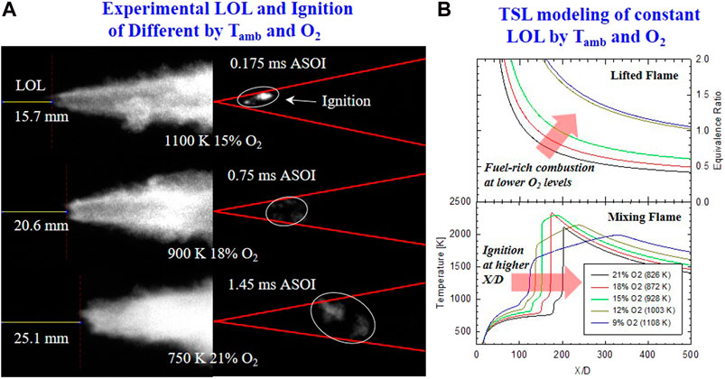
FIGURE 8. (A) Time-averaged OH* chemiluminescence (left) and Instantaneous HS combustion luminosity (right) of initial ignition. Conditions of Tamb and O2 are given in each row. Same Pinj of 75 MPa, and ρamb of 14.8 kg/m3(B) TSL simulation results of ϕ (top) from lifted flame along spray axis, and spray core temperature (bottom) from mixing model. LOL is fixed by a different combination of Tamb and O2. Other conditions are similar with Pinj = 75 MPa, ρamb = 14.8 kg/m3.
In Figure 8A, both ID and LOL are shortened as Tamb increases. This further shows a strong sensitivity of Tamb to ID and LOL compared to ambient O2 concentration, as discussed above and shown in Figures 4, 6. Earlier ignition at high Tamb is also observed closer to the injector nozzle with stronger and more concentrated ignition spots. As Tamb decreases, ignition happens further downstream and more outspread radially. The lower intensity of ignition signal from flame luminosity images suggests leaner combustion (but still rich due to high dilution) at lower Tamb due to longer fuel-air mixing time before high-temperature ignition event. The observation from all DME experiments (Table 1) is described generally as the following: at the same O2 concentration, as Tamb increases, high-temperature (earlier) ignition tends to occur closer to LOL location. The combustion signal is stronger with a more confined region of local ignition spots near the spray-plume edge. For the same Tamb, as O2 decreases, ID became longer, and the location of ignition is located further downstream away from LOL location. However, ignition tends to maintain closer to the spray-core or jet centerline. This is because the air entrainment rate into spray is likely to be the same with similar injection pressure and ambient density for current consideration of Tamb and O2. Because the effect of Tamb has been shown to affect ignition more than the impact of O2 consistently, radial expansion of initial high-temperature ignition is likely insignificant. Secondly, lower O2 ambient results in more insufficient oxygen in the spray core (given the same mixing rate and air entrainment from similar Pinj and ρamb). Therefore, it was more favorable for ignition to form at the spray-plume edge in which it is more reactive with higher Tamb and more available oxygen.
Perhaps this observation on the ignition of DME flame is also caused by DME fuel chemistry's high reactivity to enhance ignition propensity even under low O2 concentration. This allows for a more seamless transition from first-stage low-temperature combustion to second-stage high-temperature combustion in DME reacting spray compared to diesel. This suggests that low temperature or cool-flame chemistry is more important to determining lift-off length in diesel more than in DME flame. This is further observed from the flame temperature from the TSL mixing model result in Figure 8B. It is shown that the difference in first-stage ignition locations (first temperature rise) and second-stage ignition (second temperature rise toward maximum flame temperature) is almost the same for a different combination of Tamb and O2. This shows that both low and high-temperature reactions of DME respond equally to the change in Tamb. The peak temperature is affected solely by the concentration of O2 with a higher peak temperature as O2 increases. However, peak temperature was reduced for the case of 21% O2. This might be because the charge's reactivity is significantly reduced at a low Tamb of 828 K, giving fuel and air a longer time to mix (lower local Φ) before ignition. This can be seen in Φ vs. X/D profile of spray core in lifted flame in Figure 8B (Top) with Φ reduced from slightly rich to below stoichiometry. It is shown that under highly diluted conditions or low ambient temperature, ignition at the flame front would occur further downstream as air entrainment continues with the expansion of the spray area. This leads to a more widespread ignition location, and the ignition intensity is reduced, as seen in experimental HS natural flame luminosity images.
3.3.2 Effect of Ambient Density and Injection Pressure
The OH* chemiluminescence and HS natural luminosity images in Figure 9A also show the ignition and flame stabilization mechanism for DME combustion under Pinj and ρamb. While longer LOL is seen for higher Pinj, ignition occurs earlier and closer to the injector nozzle, the earlier ignition at higher Pinj could be due to uncertainty in the actual start of injection, which was not captured simultaneously with HS natural luminosity imaging. With lower Pinj, ignition occurring closer to the nozzle side is possibly due to the higher spray core equivalence ratio that enhances ignition propensity. Under similar Pinj, ignition time and location were relatively the same for different ρamb of 25 and 30 kg/m3. It is interesting to notice that ignition is consistently located near the flame core of higher ρamb and Pinj than baseline conditions. This suggests that the radial location of the ignition seems to depend on Tamb rather than other factors considered in the current study. The TSL model in Figure 9B shows the result of the equivalence ratio and flame-core temperature over the spray axis for different Pinj-ρamb combinations that result in the same similar LOL. It was demonstrated that ID became longer as Pinj increase or ρamb decreases. The ignition location farther downstream is likely caused by injection velocity (by higher Pinj) rather than by lower ρamb.
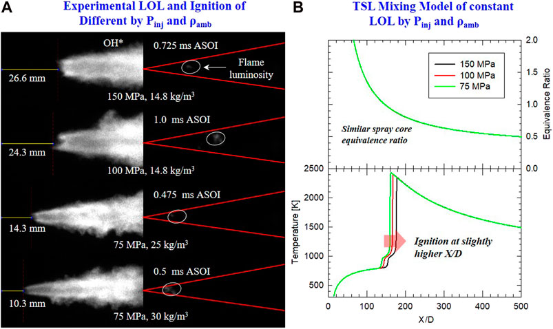
FIGURE 9. (A) Time-averaged OH* chemiluminescence (left) and instantaneous HS combustion luminosity (right) at initial ignition. Conditions of Pinj and ρamb are given in each row. Other conditions are similar: Tamb = 900 K, 18% O2. (B) TSL simulation results ϕ (top) from lifted flame along spray axis, and spray core temperature (bottom) from mixing model. LOL is fixed by different combinations of Pinj and ρamb. Other conditions are similar with Tamb = 900 K, 18% O2.
3.4 Effect of Mixing Constant on Lift-Off Length
Turbulence and combustion models have been known to be sensitive to LOL predictions under different values of mixing constants (Mc). The larger the mixing constant, the more the flame moves downstream, lowering the lift-off length. This was explained by the loss of heat and active radicals from the flame region, which causes the ignition to be postponed further downstream (Pei et al., 2013). This would be more pronounced at lower oxygen conditions where chemistry is slow, and the mixing effect is higher. However, the ignition delay is not so sensitive to constant mixing because ignition occurs in a chemically more active and mixing limited (lower scalar dissipation) region. The epsilon coefficient for k-epsilon models is critical in influencing mixing and hence the lift-off length varies. As seen in Eq. 5, Ceps1 (Cɛ1 in the equation) is a significant contributor to the turbulent dissipation transport, which influences the velocity gradient of the fluid, thus effecting mixing. Hence, the Cɛ1 constant was varied from 1 to 1.5 to evaluate its effectiveness.
Pei et al. (Pei et al., 2013) found a similar result with dodecane spray combustion lift-off validations with Euclidean minimum spanning trees (EMST) and probability density function (PDF) turbulence models. Mixing constants were influential in getting the numerical lift-off lengths to match experimental observations with little change in ignition delay predictions.
A comparison of the experiment and CFD predicted LOL is shown in Figure 10. CFD simulation was performed for oxygen concentration from 9 to 21%. LOL in CFD simulation was defined similarly to LOL from experimental OH* chemiluminescence imaging: 8% rise of maximum OH mass fraction during the steady-state period. Initial CFD configuration (with Mc of 1.42) was calibrated to match LOL at 18% O2 condition using an Mc of 1.25. It is clearly shown that the numerical LOL is shortened significantly by at least 20 mm by reducing Mc from 1.42 to 1.25. An example of the effect of mixing constant for LOL is shown in Figure 7B for OH mass fraction and temperature at the condition of 8% O2. It is also worth noting that the ignition event is not affected significantly by mixing constant. Ignition delay is postponed by only 2.7 µs (by maximum CH2O definition). Pei et al. (Pei et al., 2013) also showed similar results for diesel reacting spray with a very subtle change in ID as the mixing constant is changed. This was explained because ignition occurs near the spray core where scalar dissipation rates are low. At the same time, the lift-off location appears further downstream and away from the jet centerline where scalar dissipation rates are much higher. It was also reported that the mixing constant is 1.0 for diesel reacting spray to match LOL, but a mixing constant of 2.5 (or lower) is needed to give the best results of mixture fraction for a non-reacting spray of diesel. A further experiment of DME non-reacting spray is necessary to validate the current selection of mixing constant on fuel mixture fraction.
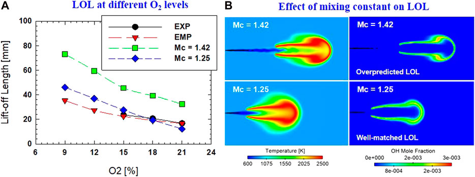
FIGURE 10. (A) Comparison of LOL between experiment (EXP), empirical equation (EMP), and CFD predictions. CFD prediction of different mixing constants (Mc = 1.42 and Mc = 1.25) was also presented; (B) Example of temperature and OH distributions from CFD simulation by different values of mixing constant.
3.5 Ignition and Lift-Off Length: Comparison DME and Diesel
The correlations between ID and LOL under different ambient and injection conditions for DME and diesel are summarized in Table 2. We established correlations for diesel spray using experimental diesel data from the online ECN database (www.sandia.gov/ECN/) for the only experiment with a nozzle diameter of 180 µm (the same nozzle diameter used in the current study). ID from a CFD simulation was also extracted for establishing the empirical correlation for DME reacting jet. Further calculation of LOL from CFD simulation for different conditions (Tamb, O2, Pinj, ρamb) is needed to establish an empirical LOL model for DME reacting spray.
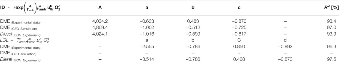
TABLE 2. Coefficients from regression model of ID and LOL for DME and diesel.
A similar sign (positive or negative) for each parameter implies a similar trend in each factor's sensitivity on ID or LOL. It is interesting to see that the change in ρamb has a higher impact (|a| = 1.016) on diesel ignition than on DME (|a| = 0.633). This means, for the same increase in ρamb, the difference in ID between DME and diesel increases. The effect of Pinj on ID of DME reacting spray is opposite to that of diesel. This needs further investigation, with more testing of the simultaneous measurement of the start of injection and the time of ignition. The beginning of injection for injection of liquid DME could depend on the compatibility of injector behavior (needle opening stage) with DME properties (e.g., higher compressibility of DME than diesel). Further study is needed to address DME flow phenomena in the injector nozzle to characterize the early stage of spray development, which could be critical for determining the ignition event. Using correlation in Table 2, the effects of Tamb and O2 on ID of DME and diesel are demonstrated in Figure 11A,B, respectively. DME has a shorter ID than diesel, with the difference in each fuel's ID slightly reduced as Tamb increases. At low Tamb (<900), the ID of DME is 1.0 ms shorter than that of diesel. As Tamb increases (>1000 K), less than 0.3 ms difference in ID of DME and diesel was observed. Over a wide range of O2 levels (9–21%), the ID of DME is shorter (0.7–1.0 ms) than that of diesel.
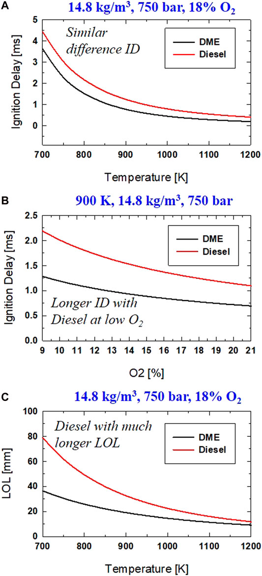
FIGURE 11. Comparison of DME and Diesel for (A) Ignition delay at different Tamb; (B) Ignition delay at different O2, (C) LOL at different Tamb.
The correlation of LOL between DME and diesel by the coefficients in Table 2, shows a fascinating comparison. The smaller magnitude of coefficient "a" indicates a smaller effect of Tamb on LOL of DME than that of diesel. This is probably due to the higher reactivity of DME than that of diesel. Next, an almost identical value of coefficient "b" implies the same level of impact from ρamb on LOL of both DME and diesel under similar conditions. This was explained by the little effect on the degree of fuel-air mixing (percent of stoichiometric air entrainment) before combustion at LOL location as ambient density changes as induced changes in LOL is nearly compensated by density induced change in air entrainment rate (Siebers and Higgins, 2001). A similar trend of longer LOL is seen for DME, and diesel reacting spray as Pinj increases or O2 decreases.
A high statistical value of R2 underlines the observation that a DME reacting spray experiment is reproducible under similar testing or simulation conditions. When compared to the coefficients found from the ECN database of equal nozzle diameter, there is excellent agreement on the effect of ambient temperature, ambient density, and oxygen concentration. There is still some difference in the influence of injection pressure on ignition delay. Moreover, some measurements at extreme conditions of low ambient temperature and/or low oxygen concentration were excluded from the current correlation due to low repeatability. The combustion vessel's limited geometry also restricts the LOL measurement of a free jet (no wall interaction or charge recirculation). Nevertheless, the established correlation of ID and LOL from the experiment of DME reacting spray could be further used as validation for the numerical model to gain further insights on ignition and flame stabilization and the emissions of intermediate species soot, and NOX.
Maps of Tamb-O2 and Pinj-ρamb are introduced in Figure 12 to study the combined effect of different parameters on DME and diesel. The difference between DME and diesel on ID and LOL are displayed. This difference implies that a certain level of adjustment in operating conditions (Tamb, O2, Pinj, and ρamb) is required when applying DME to a diesel engine. It is well known that ID and LOL are both critical factors in engine design and operating strategy. Understanding the influence of fuel chemistry on these parameters could lead to further optimization of the combustion system.
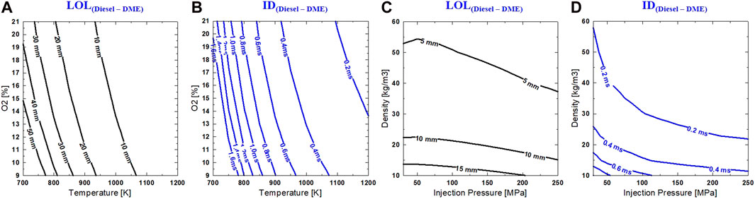
FIGURE 12. (A,B) Difference in LOL and ID between Diesel and DME in Tamb–O2 (same Pinj = 750 bar and ρamb = 14.8 kg/m3) and Pinj–ρamb (same Tamb = 900 K and O2 = 18%) mappings (C,D).
Ambient density mapping in Figure 12 provides the difference between diesel over DME on both LOL and ID. First, the contour of LOL and ID on T-O2 indicates a very similar sensitivity of DME and diesel flame under the influence of temperature and oxygen concentration. A significant difference between DME and diesel occurs at LTC conditions of low ambient temperature and high dilution with much longer LOL and ID with diesel reacting spray. For example, at 800 K and 15% O2, LOL is ∼30 mm longer, and ID is ∼1.1 ms longer with diesel fuel. This implies that diesel combustion moves downstream and closer to the wall. This could potentially lead to higher heat transfer loss. On engine application, higher combustion loss could occur if mixing or temperature is not sufficient, or interaction of spray-wall or spray piston is not optimized for good mixing. This usually leads to more effort in optimizing injector-piston design for the late-cycle combustion of diesel.
On the other hand, with rapid DME ignitability and a much shorter LOL, it is possible that an open-bowl type with less fuel penetration would allow for most combustion of DME to occur under free-jet combustion. A minimum degree of flame-wall interaction can result in low wall heat transfer. DME can also be used for different combustion systems such as conventional ω-bowl or stepped lip bowl if the design is proper for flame-wall interaction to optimize the late-cycle oxidation process. Another example of a unique piston, Wave-type, which Volvo developed (Eismark et al., 2019) in recent years, could also allow for in-cylinder dilution of recirculating charge in a radial direction. This could improve DME combustion's thermal efficiency due to lower flame temperature by introducing in-cylinder dilution, which results in a lower specific heat ratio. The high reactivity of DME could be an advantage that allows for ignition/combustion under extremely diluted conditions.
Under the selected range of ambient density and injection pressure, the difference between DME and diesel on LOL and ID is more sensitive to ambient density than injection pressure. At the same injection pressure, increased ambient reduces the difference in ID and LOL between these fuels. Under the ambient density of 25 kg/m3, increasing injection pressure does not significantly change the difference between ID and LOL of the fuels, especially for injection pressure of 100 MPa or higher. At higher ambient density and increased injection pressure, mixing and air entrainment are significantly improved, the difference between IDs of DME and diesel is minimal (<0.2 ms). However, the LOL of diesel is still longer (at least 5 mm for most conditions in Pinj–ρamb map) than DME.
3.6 Further Discussion on Ignition and Flame LIFT-OFF Mechanism Under DME Reacting Spray
A simplified conceptual model of DME reacting spray is shown in Figure 13 in comparison to diesel spray. Ignition and flame stabilization mechanisms were considered under two ambient conditions: 1) high temperature and low dilution; and 2) LTC. Other conditions of Pinj and ρamb are kept the same for comparison purposes. Collective information from the current study and other published literature was considered to reflect the main difference between DME and diesel reacting spray under these two ambient conditions.
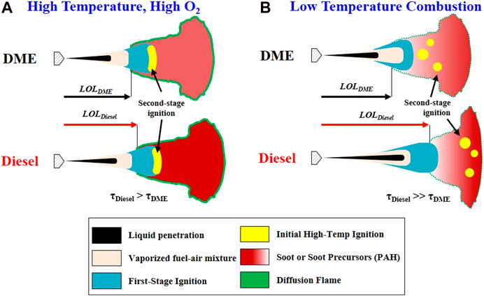
FIGURE 13. Conceptual Mechanism of DME and Diesel reacting spray under (A) High temperature, high O2 concentration, and (B) Low-temperature combustion.
High Temperature, High O2condition: Under any ambient condition, DME shows a shorter liquid length and shorter vapor/flame penetration than diesel. Shortly after fuel is vaporized and mixed with air, first-stage or low-temperature ignition occurs with low-temperature reactions (CH2O formation) in both DME and diesel combustion. Initial high-temperature ignition occurs immediately after the low-temperature region with shorter ignition delay in DME than in diesel. The location of high-temperature ignition depends on ambient temperature and O2. At high temperature and high O2, ignition tends to occur in the central region of the spray. Given the higher reactivity, high-temperature ignition is expected to locate at a distance closer to the nozzle with DME than with diesel. As flame is stabilized, DME shows shorter LOL as compared to diesel. The intensity of DME flame luminosity is much lower than that of diesel, indicating lower soot formation in DME flame. Further comparison using flame natural luminosity imaging between DME and diesel is provided in supplementary materials.
Low-Temperature Combustion: The ID and LOL difference between DME and diesel become larger in the LTC condition. In DME reacting spray ID increases at LTC condition, and ignition occurs at multiple locations further downstream, rather than a more localized ignition region as seen at high Tamb conditions. Both first-stage (low temperature) and second-stage (high temperature) ignition processes in DME flame extend equally as ambient condition moves toward LTC. Meanwhile, under LTC conditions, the first-stage ignition in diesel flame is delayed. Still, the second-stage ignition could be prolonged even further until the appearance of a highly exothermic reaction during a high-temperature second-stage period. Therefore, intermediate species during cool-flame combustion are more critical in a diesel flame than in a DME flame. This may lead to a location further downstream where high-temperature ignition occurs in diesel combustion. During the first-stage combustion, the ID increase is likely responsible for diesel’s overall longer ID than DME. Under LTC condition, longer LOL and higher flame penetration of diesel than DME suggest that most combustion of diesel occurs near the piston wall given the limited geometry of the combustion chamber; hence spray-wall interaction occurs more with diesel combustion. Soot formation is likely to occur near the wall, with DME still producing less soot than diesel due to its chemical property. The transition of intermediate reaction occurs between the high concentration of soot formation region and first-stage ignition. This intermediate reaction is relatively short or faster in the DME reaction when compared to diesel.
Compression ignition application using DME (engine and combustion vessel experiments) as fuel have been researched in several studies (Mitsugi et al., 2015; Lim and Lee, 2016; Benajes et al., 2018; Zubel et al., 2019; Han et al., 2020), which found that DME combustion behaves similarly to diesel. This is also in agreement with the findings of the current study. Due to having a lower heating value than diesel, a higher amount of DME fuel is typically required to meet a similar engine load as with diesel fuel. An example of heat-release rate calculation from pressure rise in the constant-volume combustion vessel experiment is shown in supplementary materials. An increase in nozzle diameter is usually preferred over an increase in injection pressure (more pumping work required) to compensate for the lower heating value of DME.
A change in nozzle diameter would perhaps result in a different location of ignition in a radial direction. Larger Do would possibly have ignition located more outward radially due to a potentially larger spray cone angle. Another hypothesis is that DME evaporates so quickly and is highly reactive, so the effect of nozzle diameter would be insignificant on ignition location. This is also supported by the experimental finding of different Do in Ref (Pickett and Siebers, 2005), with only a small decrease in LOL as Do is reduced. While it is widely accepted and shown that smaller orifice diameter reduces soot formation due to rapid mixing with higher air entrainment rate, there is a lack of a conclusive correlation between orifice diameter on ID in literature. Both a recent study (Nishida et al., 2017) and a previous study (Pickett and Siebers, 2005) show a slightly shorter ID with a smaller nozzle diameter. Still, nozzle diameter is more critical to liquid length and LOL rather than ignition. This suggests that nozzle diameter could be mostly responsible for the spatial aspect of ignition or flame stabilization mechanisms, especially for DME, as the fuel atomization and vaporization processes are already fast due to its physical properties. The physical delay should hardly be affected, hence there would be an insignificant contribution to total delay in physical and chemical processes.
4 Conclusion
The present study performed experiments on DME reacting spray in an optically accessible constant-volume combustion vessel over a wide range of conditions, examining the effect of ambient temperature (Tamb), oxygen concentration (O2), injection pressure (Pinj), and ambient density (ρamb) on ignition delay (ID) and flame lift-off length (LOL). It analyzed the results by using ignition delay (photodiode measurement) and lift-off length (OH* chemiluminescence) to establish correlations for DME spray. Overall, there was also good agreement on the correlation of DME spray with diesel spray in the literature on this subject. The experimental values of LOL and ID were also compared to the CFD simulation. The previous CFD model was then recalibrated to achieve a better prediction of LOL. Both experiments and numerical models provide further insight into the ignition and flame stabilization mechanisms of DME. The main conclusions of the current work are summarized as follows:
• The ID and LOL mechanisms of DME were very similar to that of diesel with low Tamb, low O2, low ρamb, or high Pinj results in longer ID or longer LOL. It was found that ID and LOL are most sensitive to Tamb and ρamb changes compared to O2 and Pinj.
• The location of ignition in the DME flame depends strongly on Tamb. At high Tamb, the ignition of DME is localized in a dense spot (central region of spray) near the LOL location. As Tamb decreases, ignition occurs further downstream in a more dispersed region.
• The two-stage ignition process in a DME flame was shown using the TSL model in the first-stage, and in the second-stage it responded equally to the change of Tamb. This suggests a seamless transition between low temperature or cool flame to high-temperature combustion of DME under different ranges of Tamb.
• The CFD simulation predicts ignition delay well at higher Tamb and high O2 conditions. The discrepancy between CFD and experiment increases by more than 0.5 ms, mostly as Tamb decreases below 750 K. The dilution effect of different O2 levels on the ID were captured well by the CFD simulation using the previously established definition of ignition delay by CH2O formation profile.
• Mixing constant was found to be an essential factor in CFD simulation in determining LOL location in DME flame. There was no significant change in ID as the mixing constant was varied. Although LOL was matched better with the experimental measurement, further calibration of the CFD model on turbulence and combustion models will improve the prediction of LOL over a wide range of ambient and injection conditions.
• A comparison of ID and LOL was made between DME and diesel. Under similar conditions, DME shows shorter ID and shorter LOL as compared to diesel.
The present study discussed the difference between the conceptual mechanism of DME and diesel combustion and established that further research and literature reviews are needed to support the characterization of DME combustion, which would help to optimize engine applications. For example, the effect of nozzle diameter on DME combustion was not examined in the current study. Further experiments examining extreme LTC conditions (low Tamb, low O2) are needed to provide data to calibrate the empirical correlation of ID and LOL for DME combustion. Spray-wall interaction is also expected under LTC conditions for DME flame. The benefits of this interaction require further development to optimize both injector nozzle configuration and wall or piston bowl design.
Author Contributions
KC, writing, data analysis; AM, CFD simulation, review; XZ, support CFD simulation; S-YL, review
Funding
The NSF/DOE program (NSF-1258720) provided support for this work under NSF program manager Song-Charng Kong and DOE program manager Gurpreet Singh.
Conflict of Interest
The authors declare that the research was conducted in the absence of any commercial or financial relationships that could be construed as a potential conflict of interest.
Acknowledgments
The authors thank Zhihao Zhao (Ph.D. Student at Michigan Tech) for assisting with computational simulation tasks.
Supplementary Material
The Supplementary Material for this article can be found online at: https://www.frontiersin.org/articles/10.3389/fmech.2021.547204/full#supplementary-material.
References
Arcoumanis, C., Bae, C., Crookes, R., and Kinoshita, E. (2008). The potential of di-methyl ether (DME) as an alternative fuel for compression-ignition engines: a review. Fuel 87 (7), 1014–1030. doi:10.1016/j.fuel.2007.06.007
Bae, C., and Kim, J. (2016). Alternative fuels for internal combustion engines. Proc. Combust. Inst. 36 (3), 3389–3413. doi:10.1016/j.proci.2016.09.009
Beale, J. C., and Reitz, R. D. (1999). Modeling spray atomization with the Kelvin-Helmholtz/Rayleigh-Taylor hybrid model. At. Sprays. 9 (6), 623–650. doi:10.1615/AtomizSpr.v9.i6.40
Benajes, J., Novella, R., Hernández-López, A., and Kokjohn, S. (2018). Numerical optimization of the combustion system of a HD compression ignition engine fueled with DME considering current and future emission standards. SAE Tech. Pap. 2018, 16. doi:10.4271/2018-01-0247
Bhagatwala, A., Luo, Z., Shen, H., Sutton, J. A., Lu, T., and Chen, J. H. (2015). Numerical and experimental investigation of turbulent DME jet flames. Proc. Combustion Inst. 35 (2), 1157–1166. doi:10.1016/j.proci.2014.05.147
Broadwell, J. E., and Lutz, A. E. (1998). A turbulent jet chemical reaction model: NOx production in jet flames. Combust. Flame. 114 (3), 319–335.
Cung, K., Bhagat, M., Zhang, A., and Lee, S.-Y. (2013a). Numerical study on emission characteristics of high-pressure dimethyl ether (DME) under different engine ambient conditions. SAE Tech. Pap. 2013, 16. doi:10.4271/2013-01-0319
Cung, K., Bhagat, M., Zhang, A., and Lee, S. Y. (2013b). Numerical study on emission characteristics of high-pressure dimethyl ether (DME) under different engine ambient conditions. SAE Tech. Pap. 2, 16. doi:10.4271/2013-01-0319
Cung, K., Bitsis, D. C., Briggs, T., Kalaskar, V., Abidin, Z., Shah, B., et al. (2018). Effect of micro-hole nozzle on diesel spray and combustion. SAE Int. 2018, 13. doi:10.4271/2018-01-0301
Cung, K. D. (2015). Spray and combustion characteristics of dimethyl ether under various ambient conditions: an experimental and modeling study. Dissertation. Houghton (MI): Michigan Technological University.
Cung, K., Johnson, J., and Lee, S.-Y. (2015). Development of chemical kinetic mechanism for dimethyl ether (DME) with comprehensive polycyclic aromatic hydrocarbon (PAH) and NOx chemistry. SAE Int. 2015, 7. doi:10.4271/2015-01-0807
Cung, K., Moiz, A. A., Zhu, X., and Lee, S.-Y. (2016a). Ignition and formaldehyde formation in dimethyl ether (DME) reacting spray under various EGR levels. Proc. Combustion Inst. 36, 3605–3612. doi:10.1016/j.proci.2016.07.054
Cung, K., Moiz, A. A., Zhu, X., and Lee, S.-Y. (2017). Ignition and formaldehyde formation in dimethyl ether (DME) reacting spray under various EGR levels. Proc. Combustion Inst. 36 (3), 3605–3612. doi:10.1016/j.proci.2016.07.054
Cung, K., Zhu, X., Moiz, A. A., Lee, S.-Y., and De Ojeda, W. (2016b). Characteristics of formaldehyde (CH2O) formation in dimethyl ether (DME) spray combustion using PLIF imaging. SAE Int. J. Fuels Lubr. 9 (1), 138–148. doi:10.4271/2016-01-0864
Curran, H., Fischer, S., and Dryer, F. (2000). The reaction kinetics of dimethyl ether. II: low‐temperature oxidation in flow reactors. Int. J. Chem. Kinetics. 32 (12), 741–759. doi:10.1002/1097-4601(2000)32:12<741::AID-KIN2>3.0.CO;2-9
Dec, J. E. (1997). A conceptual model of DI diesel combustion based on laser-sheet imaging*. SAE Tech. Pap. 1997, 14. doi:10.4271/970873
Dec, J. E., and Espey, C. (1998). Chemiluminescence imaging of autoignition in a DI diesel engine. SAE Int. 1998, 27. doi:10.4271/982685
Eismark, J., Andersson, M., Christensen, M., Karlsson, A., and Denbratt, I. (2019). Role of piston bowl shape to enhance late-cycle soot oxidation in low-swirl diesel combustion. SAE Int. 2019, 18. doi:10.4271/03-12-03-0017
Fischer, S., Dryer, F., and Curran, H. (2000). The reaction kinetics of dimethyl ether. I: high‐temperature pyrolysis and oxidation in flow reactors. Int. J. Chem. Kinetics. 32 (12), 713–740. doi:10.1002/1097-4601(2000)32:12<713::AID-KIN1>3.0.CO;2-9
Han, D., Mungal, M., Zamansky, V., and Tyson, T. (1999). Prediction of NOx control by basic and advanced gas reburning using the Two-Stage Lagrangian model. Combust. Flame. 119 (4), 483–493.
Han, S.-W., Shin, Y.-S., Kim, H.-C., and Lee, G.-S. (2020). Study on the common rail type injector nozzle design based on the nozzle flow model. Appl. Sci. 10 (2), 549. doi:10.3390/app10020549
Higgins, B., Siebers, D. L., and Aradi, A. (2000). Diesel-spray ignition and premixed-burn behavior. SAE Int. 2000, 26. doi:10.4271/2000-01-0940
Higgins, B., and Siebers, D. L. (2001). Measurement of the flame lift-off location on DI diesel sprays using OH chemiluminescence. SAE Int. 2001, 17. doi:10.4271/2001-01-0918
Khanh Cung, A. Z., and Seong-young, L. (2015). “Ignition and formaldehyde formation in dimethyl ether spray combustion: experiment and chemical modeling,” in 9th U.S. National Combustion Meeting, Cincinnati, OH, May 17–20, 2015.
Lim, O., and Lee, S. (2016). Influence of nozzle hole diameter and orifice diameter on dme spray to get the similar heat value with diesel spray using the constant volume chamber. Int. J. Automotive Technol. 17 (6), 1023–1031. doi:10.1007/s12239-016-0100-3
Lim, O. T., and Iida, N. (2015). A study on the spray and engine combustion characteristics of diesel–dimethyl ether fuel blends. Proc. Inst. Mech. Eng. D J. Automobile Eng. 229 (6), 782–792. doi:10.1177/0954407014539673
Mitsugi, Y., Wakabayashi, D., Tanaka, K., and Konno, M. (2015). High-speed observation and modeling of dimethyl ether spray combustion at engine-like conditions. SAE Int. J. Engines. 9 (1), 12. doi:10.4271/2015-01-1927
Musculus, M. P. B., Miles, P. C., and Pickett, L. M. (2013). Conceptual models for partially premixed low-temperature diesel combustion. Prog. Energ. Combustion Sci. 39 (2–3), 246–283. doi:10.1016/j.pecs.2012.09.001
Nishida, K., Zhu, J., Leng, X., and He, Z. (2017). Effects of micro-hole nozzle and ultra-high injection pressure on air entrainment, liquid penetration, flame lift-off and soot formation of diesel spray flame. Int. J. Engine Res. 18 (1–2), 51–65. doi:10.1177/1468087416688805
Park, S., and Lee, C. (2014). Applicability of dimethyl ether (DME) in a compression ignition engine as an alternative fuel. Energ. Convers. Manag. 86, 848–863. doi:10.1016/j.enconman.2014.06.051
Payri, R., Salvador, F. J., Manin, J., and Viera, A. (2016). Diesel ignition delay and lift-off length through different methodologies using a multi-hole injector. Appl. Energ. 162, 541–550. doi:10.1016/j.apenergy.2015.10.118
Pei, Y., Hawkes, E. R., and Kook, S. (2013). Transported probability density function modelling of the vapour phase of an n-heptane jet at diesel engine conditions. Proc. Combust. Inst. 34 (2), 3039–3047. doi:10.1016/j.proci.2012.07.033
Pfahl, U., Fieweger, K., and Adomeit, G. (1996). “Self-ignition of diesel-relevant hydrocarbon-air mixtures under engine conditions,” in Symposium (international) on combustion. (Elsevier), 781–789.
Pickett, L. M., Caton, J. A., Musculus, M. P. B., and Lutz, A. E. (2006). Evaluation of the equivalence ratio-temperature region of diesel soot precursor formation using a two-stage Lagrangian model. Int. J. Engine Res. 7 (5), 349–370. doi:10.1243/14680874JER00606
Pickett, L. M., Kook, S., Persson, H., and Andersson, Ö. (2009). Diesel fuel jet lift-off stabilization in the presence of laser-induced plasma ignition. Proc. Combust. Inst. 32 (2), 2793–2800. doi:10.1016/j.proci.2008.06.082
Pickett, L. M., and López, J. J. (2005). Jet-wall interaction effects on diesel combustion and soot formation. SAE Int. 2005, 17. 10.4271/2005-01-0921
Pickett, L. M., Siebers, D. L., and Idicheria, C. A. (2005). Relationship between ignition processes and the lift-off length of diesel fuel jets. SAE Tech. Pap. 2005, 20. doi:10.4271/2005-01-3843
Pickett, L. M., and Siebers, D. L. (2005). Orifice diameter effects on diesel fuel jet flame structure. J. Eng. Gas Turbines Power. 127 (1), 187–196. doi:10.1115/1.1760525
Pickett, L. M., and Siebers, D. L. (2006). soot formation in diesel fuel jets near the lift-off length. Int. J. Engine Res. 7 (2), 103–130. doi:10.1243/146808705x57793
Pickett, L. M., and Siebers, D. L. (2004). Soot in diesel fuel jets: effects of ambient temperature, ambient density, and injection pressure. Combust. Flame. 138 (1), 114–135. doi:10.1016/j.combustflame.2004.04.006
Reitz, R. D., and Diwakar, R. (1987). Structure of high-pressure fuel sprays. SAE Tech. Pap. 1987, 20. doi:10.4271/870598
Richards, K., Senecal, P., and Pomraning, E. (2013). CONVERGE 2.1. 0 theory manual. Middleton, WI: Convergent Science. Inc.
Schmidt, D. P., and Rutland, C. (2000). A new droplet collision algorithm. J. Comput. Phys. 164 (1), 62–80. doi:10.1006/jcph.2000.6568
Semelsberger, T., Borup, R., and Greene, H. (2006). Dimethyl ether (DME) as an alternative fuel. J. Power Sourc. 156 (2), 497–511. doi:10.1016/j.jpowsour.2005.05.082
Senecal, P. K., Pomraning, E., Richards, K. J., and Som, S. (2013). An investigation of grid convergence for spray simulations using an LES turbulence model. SAE Int. 2013, 18. doi:10.4271/2013-01-1083
Senecal, P., Pomraning, E., Richards, K., Briggs, T., Choi, C., McDavid, R., et al. (2003). Multi-dimensional modeling of direct-injection diesel spray liquid length and flame lift-off length using CFD and parallel detailed chemistry. SAE Tech. Pap. 2003, 23. doi:10.4271/2003-01-1043
Siebers, D., and Higgins, B. (2001). Flame lift-off on direct-injection diesel sprays under quiescent conditions. SAE Int. 2001, 24. doi:10.4271/2001-01-0530
Siebers, D. L., Higgins, B., and Pickett, L. (2002). Flame lift-off on direct-injection diesel fuel jets: oxygen concentration effects. SAE Int. 2002, 22. doi:10.4271/2002-01-0890
Teng, H., McCandless, J. C., and Schneyer, J. B. (2003). Compression ignition delay (physical+ chemical) of dimethyl ether-An alternative fuel for compression-ignition engines. SAE Tech. Pap. 2003, 17. doi:10.4271/2003-01-0759
Teng, H., McCandless, J. C., and Schneyer, J. B. (2002). Viscosity and lubricity of (liquid) dimethyl ether—an alternative fuel for compression-ignition engines. SAE Tech. Pap. 2002, 12. 10.4271/2002-01-0862
Wang, J., Chaos, M., Yang, B., Cool, T. A., Dryer, F. L., Kasper, T., et al. (2009). Composition of reaction intermediates for stoichiometric and fuel-rich dimethyl ether flames: flame-sampling mass spectrometry and modeling studies. Phys. Chem. Chem. Phys. 11 (9), 1328–1339. doi:10.1039/B815988B
Keywords: low temperature combustion (LTC), DME (dimethly ether), ignition delay, compression ignition (CI), flame stabilization mechanisms, lift-off length, CFD, combustion vessel
Citation: Cung KD, Moiz AA, Zhu X and Lee S-Y (2021) Ignition Process and Flame Lift-Off Characteristics of dimethyl ether (DME) Reacting Spray. Front. Mech. Eng 7:547204. doi: 10.3389/fmech.2021.547204
Received: 30 March 2020; Accepted: 11 January 2021;
Published: 08 March 2021.
Edited by:
Antonio Garcia Martinez, Universitat Politècnica de València, SpainReviewed by:
Bang-Quan He, Tianjin University, ChinaBart Somers, Eindhoven University of Technology, Netherlands
Copyright © 2021 Cung, Moiz, Zhu and Lee. This is an open-access article distributed under the terms of the Creative Commons Attribution License (CC BY). The use, distribution or reproduction in other forums is permitted, provided the original author(s) and the copyright owner(s) are credited and that the original publication in this journal is cited, in accordance with accepted academic practice. No use, distribution or reproduction is permitted which does not comply with these terms.
*Correspondence: Khanh Duc Cung, a2hhbmguY3VuZ0Bzd3JpLm9yZw==