 Haiwen Ge
 Ahmad Hadi Bakir1
 Suren Yadav
 Peng Zhao
94% of researchers rate our articles as excellent or good
Learn more about the work of our research integrity team to safeguard the quality of each article we publish.
Find out more
ORIGINAL RESEARCH article
Front. Mech. Eng., 25 January 2021
Sec. Engine and Automotive Engineering
Volume 6 - 2020 | https://doi.org/10.3389/fmech.2020.599752
This article is part of the Research TopicDesign and Application of Novel Combustion Systems for Internal Combustion EnginesView all 5 articles
In the present paper, an efficient optimization method based on Bayesian updating strategy is developed for the design of a spark-ignition engine equipped with pre-chamber. 3D computational fluid dynamics (CFD) simulation coupled with strategies including design of experiment, genetic algorithm, and machine learning methods is used to optimize the pre-chamber with desired combustion phasing. The optimization process starts from a design of experiment matrix of 11 design parameters, which are used to analytically characterize the pre-chamber geometry and set up the 3D combustion CFD. Taking CA50 as the single objective, the CFD results are then used to train the machine learning models. Different machine learning models are evaluated based on their Root Mean Square Error. Five machine learning models from five different categories are selected for second round evaluation. The trained machine learning model is used in the genetic algorithm optimization, which yields the optimized configuration and is again justified by CFD. The new CFD results based on the optimized design are added into the database to further refine the machine learning model. After 24 iterations for each selected machine learning models, the medium Gaussian support vector machine model is identified as the best method for the present application. Iterations using the medium Gaussian support vector machine model continue until a satisfactory result is achieved. Detailed combustion analysis is conducted to investigate the physical mechanism about how the design of pre-chamber influences the engine's performance. It is found that larger volume of the upper part of the pre-chamber results in stronger jet flow and turbulent intensity which further accelerates the flame propagation inside the pre-chamber, dominating the contrary effects from reduced pressure and temperature. Regression analysis shows that the radius of the pre-chamber is the most influential design parameter. The current work not only sheds light on the optimization of engine design, but also has demonstrated a general strategy applicable to the purpose of arbitrary engine optimization and mechanical system design.
Turbulent jet ignition (TJI) (Attard et al., 2010; Toulson et al., 2010; Alvarez et al., 2018) is one promising technology that allows ultra-lean combustion with high energy efficiency and low emission. The TJI system adopts a pre-chamber that houses a spark plug and optionally fuel/air injectors, which has already been adopted in natural gas spark ignition engines (Mastorakos et al., 2017). In general, stoichiometric fuel/air mixture can be supplied to the pre-chamber to ensure successful ignition, meanwhile the main chamber can accommodate sufficiently lean mixture for substantially-enhanced thermal efficiency. For the active pre-chamber design, where both fuel and air injectors equipped, accurate fuel/air mixture without EGR can be prepared for the pre-chamber. Disadvantage of this active pre-chamber option is that additional fuel system is required, which increases the cost and complexity of control, packaging, and cooling. In the case of passive pre-chamber, no fuel injector is installed inside the pre-chamber, so that the fuel/air mixture has to rely on natural scavenging during the intake stroke to enter the pre-chamber. Therefore, the passive pre-chamber design causes difficulty for precise charge preparation inside the pre-chamber, which may lead to more severe combustion instabilities and higher chance of misfire. In both options, the fuel and air mixture in the pre-chamber are ignited by the spark plug. The temperature and pressure inside the pre-chamber quickly increase. Consequently, the large pressure difference between the pre-chamber and main chamber forces the hot combustion products out of small orifices at the end of the pre-chamber, forming a hot turbulent jet igniting the compressed lean charge in the main combustion chamber. Combustion induced by this hot reacting turbulent jet occurs much more rapidly due to the spatially distributed flame-fronts (Attard et al., 2010). Less heat is transferred to the engine parts due to the fast combustion and lean mixture. Compared to the conventional SI engines that run at stoichiometric conditions and limited by engine knock, the lean mixture in the main chamber is knock free for most of the conditions and hence allows much higher compression ratio. Furthermore, relatively low combustion temperature occurring in the lean main chamber significantly reduces emissions of NOx and particulate matter (PM).
TJI has been extensively investigated both experimentally and numerically. Toulson and co-workers conducted a series of fundamental studies of TJI using an optical-accessible rapid compression machine (RCM). Toulson et al. (2012) compared conventional spark ignition and TJI in an optical single cylinder engine, and demonstrated that TJI enables faster combustion due to the multiple widely distributed ignition sites produced. Gentz et al. (2015) investigated the orifice size’s effects on TJI in a rapid compression machine (RCM). It was found that for near stoichiometric air to fuel ratios, a large nozzle that produces more spatially distributed jets would result in faster combustion progression. However, at leaner conditions a smaller diameter nozzle that produces a faster and more vigorous jet is required to initiate combustion. Gentz and Toulson (2016) further compared active and passive fueling in TJI. For passive fueling, the single orifice has better performance than the dual orifice with the same cross section area. Karimi et al. (2014) conducted an experimental and computational analysis of the hot jet ignition in a combustion vessel. The hot jet is characterized by three different jets: wall jet, wall impinging jet, and free jet. Li et al. (2019) conducted an experimental study of TJI in a RCM and a single cylinder engine. The study revealed that there are two ignition patterns in the pre-chambers depending on the diameter of orifices: flame ignition pattern with large orifice diameter and auto-ignition pattern with smaller orifice. Biswas et al. (2016) revealed two ignition mechanisms in the main chamber: jet ignition and flame ignition. Biswas and Qiao (2016) conducted an experimental study of the ignition of ultra-lean premixed H2/air mixtures by the hot jet issued by a pre-chamber with a stoichiometric mixture, visualized using simultaneous high-speed Schlieren photography and OH* Chemiluminescence. Three nozzle geometries (straight, convergent and converging-diverging) are compared. Diamond shock structures in the supersonic jets and a high-temperature zone downstream the shocks were observed, which may reduce the flammability limit in the main chamber. Combustion instability becomes noticeable near the lean-limit conditions. Biswas and Qiao (2018) further investigated the effects of spark location and equivalence ratio in pre-chamber on the ignition pattern in the main chamber. The effective ratio describing the spark location governs the flame dynamics in the pre-chamber. Bolla et al. (2019) simulated an automotive-sized scavenged pre-chamber mounted at the head of a rapid compression-expansion machine using RANS and LES. It is shown that the tilted nozzle of the pre-chamber orifice generates a swirl flow inside the pre-chamber. Benekos et al. (2020) conducted a 2D DNS study of the ignition process in the main chamber. The effect of the wall thermal boundary condition, initial mixture temperature, and equivalence ratio in the main chamber was investigated numerically. It was found that the hot jet from the pre-chamber can be broken into small kernels at cold condition of the main chamber, or forms a flame torch at the hot condition. Muller et al. (2018) investigated the ignition mechanism in the main chamber. It was found that both kinetic effects and thermal effects are important for the hot jet induced ignition process. Strong correlations between fluid dynamics, mixing and combustion are observed. Akhtar et al. (2017) investigated the effects of orifice geometry on the performance of pre-chamber using Schlieren imaging. Circular and slit shapes with the same cross-section area were considered. It was found that the slit pre-chamber can accelerate the flame propagation in the early stages. Freeman et al. (2020) developed a new design of pre-chamber with the assistance of 3D combustion CFD. The CFD results show that the pre-chamber SI engine has good improvements over the conventional gasoline SI engine, especially the fuel economy. Based on the pressure difference between main chamber and pre-chamber, the gas exchange process between them can be described by a four-stage process. Shah et al. (2015) experimentally investigated the effects of pre-chamber volume and nozzle diameter on the resultant ignition characteristics. It was found that a larger pre-chamber provides higher ignition energy which results in shortened flame development angle and combustion duration. At a given pre-chamber volume, nozzle diameter mainly affects the combustion duration. Hlaing et al. (2020) reveals a two-stage combustion mechanism in the main chamber where the latter stage is thought to be contributing to the bulk ignition of the main chamber charge. The pre-chamber heat release is correlated to the mixture strength of the pre-chamber, which affects the phasing of the pre-chamber combustion and the initial heat release in the main chamber. Tang et al. (2020) used simultaneous negative PLIF and OH chemiluminescence to visualize the gas exchange process and flame jet from the nozzles of a pre-chamber, which showed that the flame jet penetration length is much shorter than that of the pre-chamber jet. A three-stage gas exchange process is proposed. When the equivalence ratio of the pre-chamber is increased from lean to slightly rich, the pressure difference between main chamber and pre-chamber, ignition timing, and timing of peak pressure difference increases at first and then reaches a plateau. Kim et al. (2019) compared turbulent combustion models (multi-zone well-stirred reactor and G-equation) for pre-chamber ignition. G-equation model gives better predictions than the well-stirred reactor model. From above, although extensive computational and experimental work has been conducted to understand and predict pre-chamber spark ignition, the design of the pre-chamber is still largely experience-based and there is a lack of general strategy that can provide guidance toward an optimal design. Zhang et al. (2020) conducted a comprehensive 3D CFD analysis of a light-duty gasoline engine with a passive pre-chamber. A three-phase phenomenological model is proposed to describe the flame ignition behavior during pre-chamber jet combustion. Pre-chamber with swirl nozzles generates organized and repeatable swirl motion that could be beneficial for combustion. The pre-chamber nozzle umbrella angle and orientation could be further optimized for a given combustion system to achieve reduced combustion heat loss. Hua et al. (2021) compared four pre-chamber designs, passive and active fueling in engine tests. They found that the volume and number of the jet hole are two key parameters for optimizing the structure of the pre-chamber. The pre-chamber with smaller volume has better IMEP and fuel economy due to the lower heat dissipation and combustion loss in the pre-chamber. The single-hole pre-chamber studied generates a stronger hot jet than the 7-hole pre-chambers, which effectively improves the burning rate and extends the lean-burn limit.
From the manufacturing and mechanical design perspective, MAHLE Powertrain has been the leading developer in application of TJI for powertrain of passenger cars. Attard et al. (2010) demonstrated in one single-cylinder engine that the TJI can tolerate up to 54% mass fraction diluent, which results in 18% improvement in fuel economy. Attard and Parson (2010) showed that the spark plug type, orientation and electrode gap have little to no effect on jet ignition combustion. They concluded that it is partially due to the spark discharge in the pre-chamber occupies a much larger fraction of the chamber relative to conventional spark ignition. They also found that the spark plug reach has the greatest effect that is not very important for conventional SI engines.
Coupled with genetic algorithm, 3D combustion CFD has been extensively used in engine development (Shi et al., 2011). Ge et al. (2009) and Ge et al. (2010) developed automated calculation processes to optimize fuel system, piston bowl, and swirl ratio. Ge et al. (2010) developed an optimization method that simultaneously optimizes multiple operating conditions by separating the design parameters into hardware parameters and operating parameters. Ge et al. (2011) and Lee et al. (2012) combined scaling laws with the optimization method in (Ge et al., 2010) for engine combustion optimizations. Machine learning techniques have been applied to many areas of engine combustion. Moiz et al. (2018) combined machine learning with genetic algorithm and 3D CFD for engine combustion optimization. The method was applied to a heavy-duty diesel engine. Kodavasal et al. (2018) used machine learning techniques to analyze the controlling factor of cycle-to-cycle variation in a gasoline spark-ignited engine. Probst et al. (2019) used two machine learning techniques (Gaussian process and SuperLearner) in engine combustion predictions. Different optimization methods were compared. The particle swarm optimization, differential evolution, GENOUD algorithm, and micro-genetic algorithm (GA) were recommended. Badra et al. (2020) optimized the combustion system of a gasoline compression ignition engine using CFD and machine learning-grid gradient algorithm. Shah et al. (2019) used machine learning techniques to predict the ignition delay, flame speed, octane rating, and combustion phasing of multicomponent gasoline surrogates in homogenous charge compression ignition engines.
The design of the pre-chamber is the most critical component of this type of engines, which remains a challenge. The papers in literature usually investigated the effects of one or a few design parameters on engine performance. However, systematic study of the pre-chamber geometry is missing. The present paper reports an automated optimization method for pre-chamber design using 3D combustion CFD. DOE, GA, machine learning is coupled with 3D combustion CFD for optimization of the pre-chamber design for a spark-ignition engine. Different machine learning models are compared. The optimal design is compared with an averaged design and a bad design to understand how the design parameters physically influence the engine performance.
A three-dimensional port fuel injection (PFI) spark-ignition engine was simulated, which is one of the example cases of the CONVERGE. Table 1 lists the parameters of the engine configurations. For all the cases, the global equivalence ratio is set to unity. In the original engine, the spark plug is installed at the center of the cylinder head. In the present work, the spark plug is then replaced by the TJI system (c.f., Figure 1), whose bottom part has the size as the spark plug. Thus, the whole pre-chamber can be directly installed to the SI engine without making a new cylinder head. Full cycle simulations of all the engine cases were conducted, i.e., starting from EVO (exhaust valve opening, which is −579.8° ATDC) to EVO (140.2° ATDC). The gas exchange process is simulated. At the IVC (intake valve closing), the mass fraction of CO2 and H2O in the whole chamber (including main and pre-chamber) is 1.83%, which is equivalent to about 5.4% EGR.
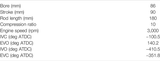
TABLE 1. Engine configurations.
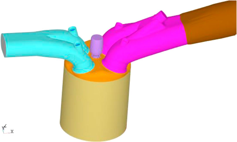
FIGURE 1. Surface of one pre-chamber SI engine.
In the present paper, a commercial CFD software CONVERGE (Richards et al., 2017) was used for engine simulation, which is based on the finite volume method. Table 2 lists the primary models used in the present simulations. Adaptive mesh refinement (AMR) and fixed embedding were used to balance efficiency and accuracy. Real fluid model, Redwich–Kwong equation of state, was employed. SAGE combustion model with PRF mechanism (Liu et al., 2012) was used for all the simulations of SI engine cases, in which the fuel is gaseous gasoline. For the simulation of the rapid compression machine, the fuel is methane. The SAGE combustion model with the GRI 3.0 mechanism was used. The SAGE combustion model treats each computational cell as a perfectly stirred reactor, i.e., there is no explicit turbulence chemistry interaction (TCI) models. Recently, Dahms et al. (2019) conducted an asymptotic analysis that showed there is implicit TCI in the multi zone SAGE model. The implicit TCI means that the performance of the combustion model depends on grid size, numeric, etc. The TCI can be fully recovered by SAGE model when the grid size and time step approaches the size of DNS. Although the present grid size and time step are not small enough to fully recover the TCI, local mesh refinement near the flame front can largely recover the TCI. Additionally, the turbulence effects are taken into account through the turbulent diffusivity, through which the TKE affects the mixing processes of energy, species, and momentum. Thus, a certain level of the turbulence effects on the combustion process has been captured by the present simulations. All the combustion simulations use unsteady RANS with RNG k–ε model (Han and Reitz, 1995). Constant diffusivities were assumed, with turbulent Prandtl number of 0.9 and turbulent Schmidt number of 0.78. Spark plug geometry was neglected in the pre-chamber. In both conventional SI engine and pre-chamber, spark ignition was modeled using a point source. Base mesh size is set to 4 mm. Three level embedding based on temperature and velocity was applied to AMR. Boundary of the pre-chamber was refined to 0.5 mm using fixed embedding. Five and three level fixed embedding were used for the nozzle and near nozzle jet flow region, respectively. Level three AMR is activated by both temperature gradient and velocity gradient.
TABLE 2. Computational models.
Launder and Spalding wall model (Launder and Spalding, 1974) is employed to treat the boundaries of the solid walls. The temperature of piston, liner, cylinder head, pre-chamber, exhaust valve bottom, exhaust valve stem, exhaust port, intake port, intake valve bottom, and intake valve stem are set to 450, 400, 400, 450, 525, 425, 400, 300, 480, and 350 K, respectively. At the inlet of intake port, the pressure is fixed to 1 atm and a perfect stoichiometric mixture of gaseous gasoline and air is set. The pressure at the outlet of exhaust port is set to 1 atm, too. Backflow with temperature of 610 K and a mixture of N2 (71.9% by mass), CO2 (19.2%), and H2O (8.9%) is applied to the outlet of exhaust port. At the beginning of the simulations (−579.8° ATDC, which is EVO), the mixtures in the main chamber and pre-chamber are assumed to be N2 (71.9% by mass), CO2 (19.2%), and H2O (8.9%). By simulating the whole cycle, the scavenging process of the main chamber and pre-chamber is covered. The predicted residuals in the main chamber and pre-chamber are more reliable. The same numerical model has been used to simulate the MSU single nozzle TJI case, which successfully reproduced in-cylinder images and the averaged pressure trace of the main chamber that will be presented in the next section. It implies that the present numerical model and mesh is able to reproduce the ignition and combustion processes in the pre-chamber and main chamber. Figure 1 shows the surface of one pre-chamber SI engine. The intake ports and exhaust ports are on the two side of x-direction, i.e., the engine is about symmetric of y-plane (y = 0). Figure 2 shows a typical mesh of the pre-chamber SI engine at −2.5° ATDC. Due to the additional volume of the pre-chamber, the compression ratio of the pre-chamber SI engine is reduced from 10.0 for the baseline engine. Fuel injection is neglected for simplification. The intake air/fuel mixture is assumed to be perfectly mixed.
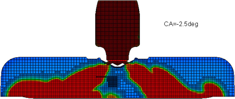
FIGURE 2. Computational mesh of one case at −2.5° ATDC.
The pre-chamber has 6 holes. The hole size and normal direction of nozzle exit are fixed. In the present study, only the geometry above the nozzle is optimized. An axi-symmetric shape is assumed for the upper part of the pre-chamber that is above the nozzle part. Thus, the geometry of upper part can be simplified as a symmetric 2D profile. The half profile is then parameterized and analytically described using 11 design parameters. Figure 3 (left) shows the sketch of an example design with the 11 design parameters. Point A is fixed and connects with the nozzle part of the pre-chamber. Points B, C, D, and E are flexible. Point B has the same radial coordinate as Point A, i.e., the part AB is vertical. Vertical coordinate of Point B is determined by design parameter “bz”. Points C and D have the same radial coordinates, which is determined by design parameter “cr.” Their vertical coordinates are determined by “cz” and “dz”. Coordinates of Point E is determined by design parameter “er” and “ez.” Radius of the pre-chamber top is set to be larger than the spark plug size to ensure that a regular spark plug can be installed to the pre-chamber. Thus, the radial coordinate of Point E has a minimal value. Design parameter “xde” is used to determine the curvature of DE. Design parameters “gz,” “hz,” and “θ” are used to determine the curve between points B and C. Table 3 lists the range of these 11 design parameters. Bezier curves are applied on the corner to ensure smooth transitions. The parameters “bz,” “dz,” “gz,” “hz,” and “θ” are physically within [0,1]. Except theta, all are set to [0.01, 0.99] to avoid potential singularity issue. For “θ”, a range of [0.2, 0.8] is chosen to avoid too sharp angles for curve BC. The minimal value of parameter “er” indicates the radial size of a conventional spark plug, i.e., the pre-chamber should be at least large enough to host a spark plug. Its maximum value is set to 1.8 based on the experience. The parameter “cr” indicates the ratio of radius at point C and point E, and thus it is larger than 1. Its minimal value is set to 1.02 to leave sufficient space for the curve DE. Its maximal value is set to 1.2 based on the experience. The minimal value of parameter “ez” indicates the minimal heights to host a conventional spark plug. Its maximal value is set to 3.0 based on the experience. The parameter “cz” is a normalized parameter describing the height of point C. Its minimal value is limited by its distance to the cylinder head, i.e., to avoid intersection with the cylinder head and maintain enough thickness of prechamber wall. Its maximal value is set to 2.0 based on the authors’ experience. The curvature parameters “xbc” and “xde” have non-negative values, with 0 for straight line and 1 for circular curve. They are set to the ranges of [0.1, 2.0] to cover a reasonable variety of curvature. Figure 3 (right) shows the three example designs. Black solid line indicates the design with all minimal parameters. Red dashed line indicates the design with all median parameters (which is the design DOE56 in “Combustion Analysis of the Optimal Design” section). Blue dotted line indicates with all maximal parameters.
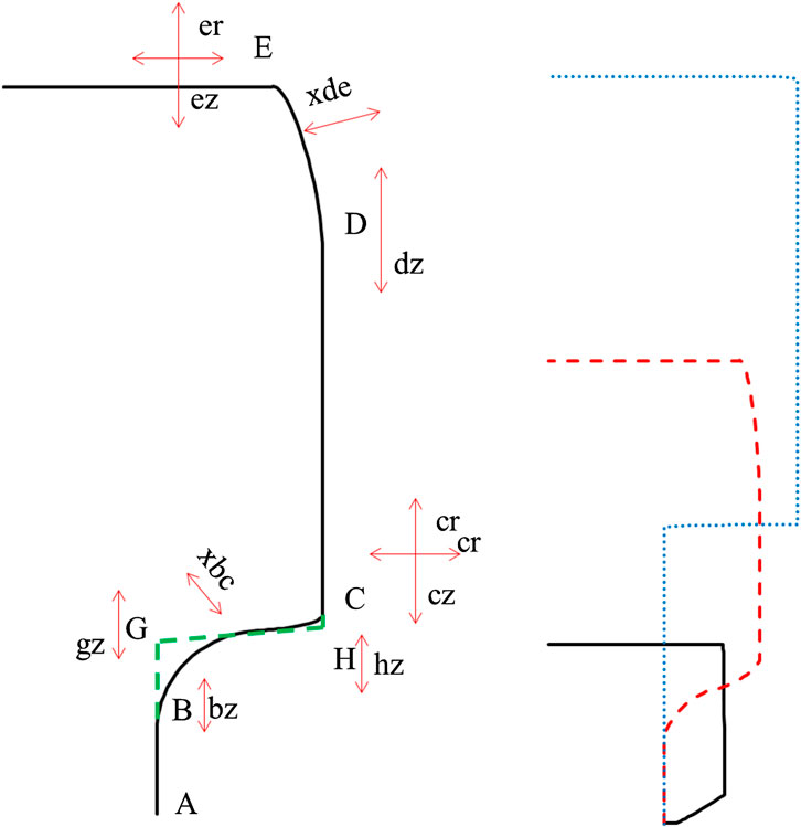
FIGURE 3. Left: design parameters of the pre-chamber. Right: design with all minimal parameters (black solid line), all median parameters (red dashed line), and all maximal parameters (blue dotted line).
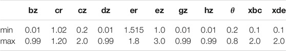
TABLE 3. Ranges of design parameters of the pre-chamber.
Figure 4 shows the sketch of the optimization method, which is based on the Bayesian updating strategy (Enright and Frangopol, 1999). The Bayesian updating strategy is a learning-by-practicing approach, in which the Bayes' theorem is used to update the probability for a hypothesis as more evidence or information becomes available. In the present application, the machine learning module is updated when more CFD results become available. The optimization starts from a DOE (design of experiment) of all the design parameters. In the present work, the size of the DOE is set to 56, which represents a small size DOE matrix with 11 design parameters. The DOE matrix is generated using Latin hypercube sampling method in Matlab. All the designs in this DOE are simulated using 3D combustion CFD. These CFD results form the first database, which is used in machine learning (ML) module for data training. Thus, the ML module can replace the 3D combustion CFD in the optimization process. Then, a genetic algorithm (GA) coupled with the trained ML module is used for optimization, which will recommend one “optimal” design(s). The “optimal” design(s) are further confirmed in the 3D combustion CFD. Thus, the role of ML+GA approach is to suggest the potential good designs, instead of accurately predicting the objective CA50. All the designs suggested by ML+GA approach will be further confirmed by the 3D CFD simulations. In another words, we judge the ML algorithm based on what design it has suggested, not the CA50 it predicted. The benefit of ML is to reduce the total number of the computational expensive 3D CFD simulations. Thus, the ML is not necessary to be a quantitative prediction tool. Instead, qualitative prediction of CFD results by the ML will be sufficient and actually is more critical than the quantitative prediction. The results of these “optimal” designs are added to the database to further improve the accuracy of the ML module. Compared to the 3D combustion CFD cases that usually take about 20 h using 72 cores, the computational time of the GA+ML option is only about a few minutes using a laptop, which is completely negligible. Thus, this method significantly reduces the computational costs by replacing the 3D combustion CFD with the ML module in the optimization. The ML module also helps to narrow down the optimal domain in the whole design space and reduces the total runs of 3D combustion CFD. The Bayesian updating approach reduces the total number of iterations. Given the nature of the GA, the final “optimal” design is the best design among all the considered designs, not the exact optimum in the whole design space (Shi et al., 2011).
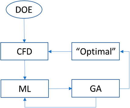
FIGURE 4. Sketch of the Bayesian updating optimization method.
The 3D combustion CFD model is validated in one MSU RCM case with pre-chamber, which operates under engine-like conditions (Gholamisheeri et al., 2017). In this case, the nozzle diameter is 3.0 mm and λ = 1.25. The initial pressure and temperature for both the experiments and simulations were 1.04 bar and 80°C, respectively. The fuel is methane. A 30 species skeletal mechanism based on GRI3.0 (Lu and Law, 2008) is used in the SAGE model. Except the reaction mechanism, all the models and settings are the same as the ones described in “Engine Configurations and Numerical Methods” section. Figure 5 shows the comparison of predicted and measured (Gholamisheeri et al., 2017) pressure in the main chamber, achieving very good agreement. Figure 6 shows comparison of experimental chemiluminescence images (Gholamisheeri et al., 2017) and predicted temperature contour in the main chamber at similar burn duration times. The principle shape of the hot jet issued from the pre-chamber has been captured reasonably. Due to the nature of the RANS model, the predicted hot jet is much smoother than the measured one. In overall, the present numerical model is capable of reproducing the TJI combustion.
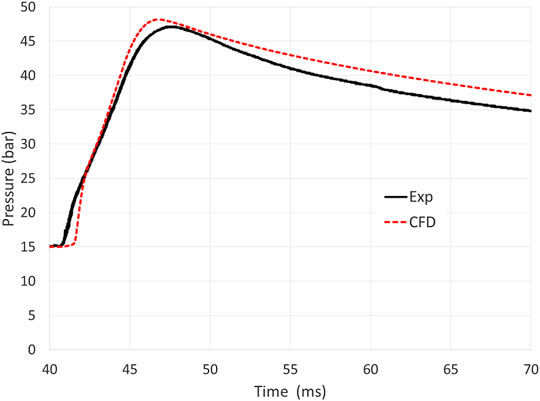
FIGURE 5. Comparison of predicted and measured pressure in the main chamber.
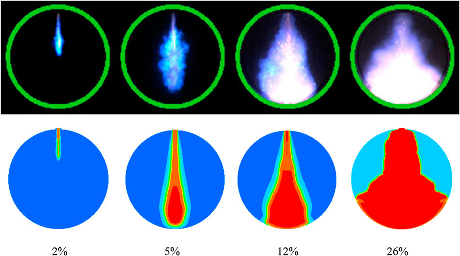
FIGURE 6. Comparison of experimental chemiluminescence images (top) and predicted temperature contour (bottom) in the main chamber at similar burn duration times.
The present CFD model is then applied to simulate the SI engine cases that are fueled with gasoline and with the pre-chamber (c.f., Figure 1). All the following results and analysis are based on the simulations of the gasoline SI engine with a passive pre-chamber. In the present work, the ML module (regression learner) and GA module in Matlab are employed for the optimization. CA50, the crank angle corresponding to 50% fuel consumption, is taken as the single objective of engine performance for simplicity. Given the same spark timing, smaller CA50 indicates faster combustion, which makes more room for spark retardation and improved fuel economy. For the ML module, cross-validation with 5 folds is used. At the first step, all the machine learning models available in the regression learner module are tested. The all design parameters listed in Table 3 are taken as the inputs of the ML modules. The CFD predicted CA50 is set as output. Table 4 shows the RMSE of all tested machine learning models. The samples are the results of the DOE matrix, which is in total 56 samples. Overall, the exponential GPR has the lowest RMSE of 2.628. Among each category, one model is selected for further evaluations, including robust linear model (Ronchetti et al., 1997), coarse tree model (Breiman et al., 1984), medium Gaussian SVM (Xu et al., 2009), bagged Tree model (Ting and Witten, 1997), and exponential GPR (Williams and Rasmussen, 2006). Figure 7 show the comparison of the predicted and actual CA50 using these five selected models. The x-axis indicates the actual CA50. The y-axis indicates the predicted CA50 using the machine learning models. It can be seen that in general all the models have poor quality of fitting. One reason is due to the small sample number (=56). The difference in fitting between difference machine learning models are more evident. Particularly, the coarse tree model has very poor fitting. Using the method illustrated in Figure 4, these five machine learning models are tested with 24 iterations. Each iteration gives one “optimal” design for each model. Figure 8 shows the CFD-predicted CA50 of the “optimal” designs from these selected machine learning models. It can be seen that relatively, the medium Gaussian SVM model (SVM) gives the most optimized design with these 24 iterations. Thus, the medium Gaussian SVM model is used for next stage optimization.
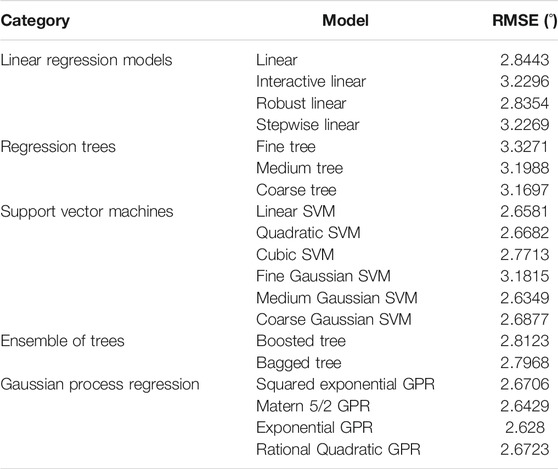
TABLE 4. RMSE of machine learning models.
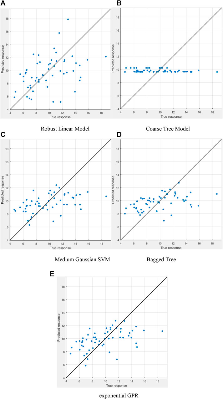
FIGURE 7. Comparison of predicted and actual CA50 values using the five selected machine learning models with the 56 samples from DOE. (A) Robust Linear Model, (B) Coarse Tree Model, (C) Medium Gaussian SVM, (D) bagged tree, and (E) exponential GPR.
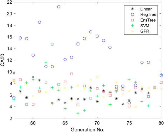
FIGURE 8. Comparisons of CFD-predicted CA50 from the five selected machine learning models.
The medium Gaussian SVM model is trained using all the CFD results (including the ones used in other machine learning models). Same method illustrated in Figure 4 is used. After 10 generations, no better design than the design “SVM67” (67 is its generation number) is found. Figure 9 shows the CFD-predicted CA50 of all the generations. The x-axis indicates the generation number. Symbols “*” indicate the 56 samples of the DOE matrix. Square symbol squares indicate the results of the medium Gaussian SVM model. Circle symbols indicate the results of the other machine learning models. Thus, the design “SVM67” that has the lowest CA50 of 2.9° ATDC is selected for further analysis. In the next section, this design is compared with design “RegTree64” that represents the worst CA50 (22.2° ATDC). Besides these two extreme points, design “DOE56” that represents an averaged design (all the design parameters are averaged values over their whole ranges) is considered in the detailed analysis, too. Its CA50 is 6.5° ATDC. With these three points, a clearer trend can be observed.
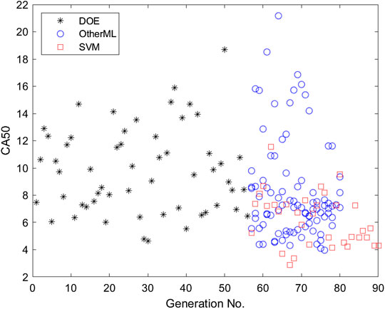
FIGURE 9. CFD-predicted CA50 of all the generations.
Figure 10 shows the comparison of predicted and actual CA50 values using medium Gaussian SVM with all the 184 samples. Comparing to the medium Gaussian SVM plot in Figure 7 that is based on 56 samples, the fitting quality has been improved. The corresponding RMSE has been reduced from 2.6349 to 2.2618. Although the optimization started from a minimal-size DOE matrix and thus the initial fitting quality is low, it has been improved gradually by adding more samples from CFD simulations into the database for training. For optimization purpose, as long as the ML+GA approach can capture the correct trend, the optimization direction will be correct. Even sometimes the ML+GA approach suggests some bad designs, it will not ruin the whole optimization process since the designs will be confirmed in the CFD simulations. Only the CFD results will be seriously considered for further analysis and hardware development, not the results predicted by the machine learning model. Thus, qualitative prediction of the CFD results by the machine learning model will be sufficient for the present optimization applications.
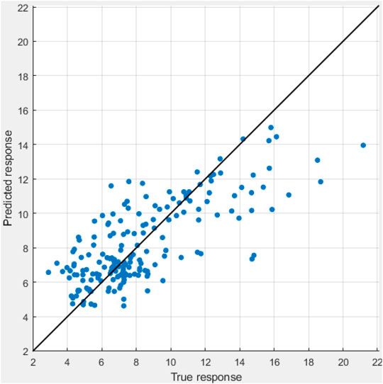
FIGURE 10. Comparison of predicted and actual CA50 values using medium Gaussian SVM with all 184 samples.
It should be mentioned that the present “optimal” design is only optimal in terms of CA50 based on the spark timing of -15° ATDC and without spark plug geometry. With other objectives and/or constraints being taken into account, the optimal design will be different. A successful optimization of CA50 will provide direct guidance toward the optimal fuel economy.
To improve the understanding of how the design parameters affect the engine performance, the selected three designs are compared. Figure 11 shows the pressure trace and heat release rate (HRR) profiles of the main chamber and pre-chamber. The design SVM67 has the earliest pressure rising, which indicates faster combustion. The design RegTree64 has the lowest peak pressure and weak HRR that indicates weak combustion in both pre-chamber and main chamber. However, right before the spark timing (CA = −15° ATDC), the design RegTree64 has higher in-cylinder pressure than the other two designs. This is due to its smaller volume of the pre-chamber than the other two designs (c.f., Figure 12), and thus has higher compression ratio. With the same boost pressure and temperature, the design RegTree64 that has higher compression ratio has higher in-cylinder pressure and temperature than the other two designs, which is a more favorable thermodynamic condition for faster combustion. However, the CA50, pressure trace and HRR indicate that RegTree64 has the slowest combustion. Apparently, the ignition process of design RegTree64 did not benefit from the more elevated thermodynamic conditions at the spark timing. The design DOE56 also has slightly higher pressure and temperature than design SVM67 at the spark timing, while its ignition process is slower than design SVM67. This implies that for the present combustion processes, thermodynamics is not the most dominant factor. The averaged mass fractions of CO2 of pre-chamber at the spark timing are 0.0246 (SVM67), 0.0230 (DOE56), and 0.0207 (RegTree64), respectively. The design SVM67 has the highest CO2 concentration in the pre-chamber, which is also not favorable for its faster combustion than the other two designs. Thus, the thermochemical condition of the whole pre-chamber is not the most dominant factor, either.
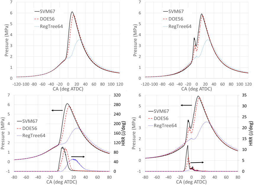
FIGURE 11. Pressure trace profiles of the main chamber (left) and pre-chamber (right).
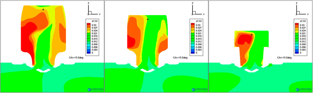
FIGURE 12. Comparison of z-velocity distributions of designs SVM67 (left), DOE56 (middle), and RegTree64 (right) at −15° ATDC.
Figure 13 shows the comparison of CO2 distributions of designs SVM67 (left), DOE56(middle), and RegTree64 (right) at -15° ATDC. The contour plots are the mass fraction of CO2 on the x-slice that is through the center of the nozzle (x = 0). The symbol “+” indicates the location of spark. The mass fractions of CO2 at the spark location at this moment are 0.02334 (SVM67), 0.0216 (DOE56), and 0.02734 (RegTree64). The high CO2 concentration at the spark location in design RegTree64 is part of the reason of its slowest ignition process. Comparing the design SVM67, the CO2 concentration of design DOE56 at the spark location is lower, which is favorable for ignition and flame propagation. However, its overall ignition process is slower than the one of design SVM67. Thus, all the thermochemical conditions of design SVM67 are not favorable for a faster ignition process. It must be due to another physical mechanism beyond the thermochemical conditions.
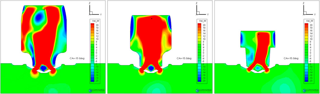
FIGURE 13. Comparison of CO2 distributions of designs SVM67 (left), DOE56 (middle), and RegTree64 (right) at −15° ATDC.
Figure 12 shows the z-velocity distributions inside the pre-chamber at the spark timing of the selected three designs. The contour plots are on the x-slice that is through the center of the nozzle (x = 0). With the piston moving to top dead center (TDC), the gas in the main chamber enters the pre-chamber through the nozzles. Consequently, jet flows are formed inside the pre-chamber. With the larger volume of the pre-chamber, the jet lasts longer in the design SVM67 than the other two designs. The flow field inside the pre-chamber is more complex in design SVM67 than the other two design as well. Many vortexes are formed in the design SVM67, creating stronger turbulence that enhances flame propagation. The z-velocities at the spark location are 14.5, 52.9, and 23.0 m/s, respectively. The relatively small upward flow velocity of design SVM67 benefits the flame propagation downward. Near the spark location, there is a region with strong downward flow that will transport the flame kernel downward. The design DOE56 has a very strong upward flow near the spark location that will put the flame kernel to the ceiling of the pre-chamber, which will cause more flame quenching. Figure 14 shows the contour plots of turbulent kinetic energy (TKE) inside the pre-chamber at the spark timing of the selected three designs. The design SVM67 has evidently higher TKE than the other two designs. And its distribution in space is more homogeneous. Higher TKE increases the turbulent flame speed and accelerates the flame propagation.
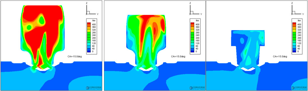
FIGURE 14. Comparison of TKE distributions of designs SVM67 (left), DOE56 (middle), and RegTree64 (right) at −15° ATDC.
Figures 15 and 16 show the contour plots of temperature of designs SVM67 (left), DOE56(middle), and RegTree64 (right) at −12.5° and −10° ATDC, respectively. The top row shows the results on the x-slice that is through the center of the nozzle (x = 0), while the bottom row shows the results on the y-slice (y = 0). It is evident that the flame propagates much faster in design SVM67 than the other two designs. The directions of flame propagation loosely correlate with the high TKE regions. Additionally, the relatively strong downward flow near the spark location moves the whole burning cloud downward, i.e., farther away from the top of the pre-chamber and less wall quenching. Since the jet flow from the nozzle that is upward is still existing, the flame cannot propagate into the central region of the pre-chamber. Instead, it propagates along the side wall. For the design DOE56, the flame kernel propagates to the top of the pre-chamber. This is due to the relatively low TKE and the strong upward flow as illustrated in Figure 12. It can be seen that the flame kernel has been partially quenched by the wall. Its flame kernel propagates into the region of side walls that has relatively stronger downward flow. The flame kernel of the design RegTree64 has a reasonable size at the early stage (c.f., right plot of Figure 15), almost comparable with the one of design DOE56. This is partially due to its relatively weak upward flow. However, comparing to the other two designs, the flame kernel of design RegTree64 does not propagate much. Its shape is not heavily distorted by the flow as the other two design. This must be due to its much lower velocity magnitude and TKE than the other two designs. Eventually, the design RegTree64 has very slow ignition process inside the pre-chamber, and consequently very slow combustion inside the main chamber. Thus, it can be concluded that the turbulent intensity and flow structure inside the pre-chamber is critical for the ignition process. A strong turbulence and large downward flow velocity are preferred for better engine performance.
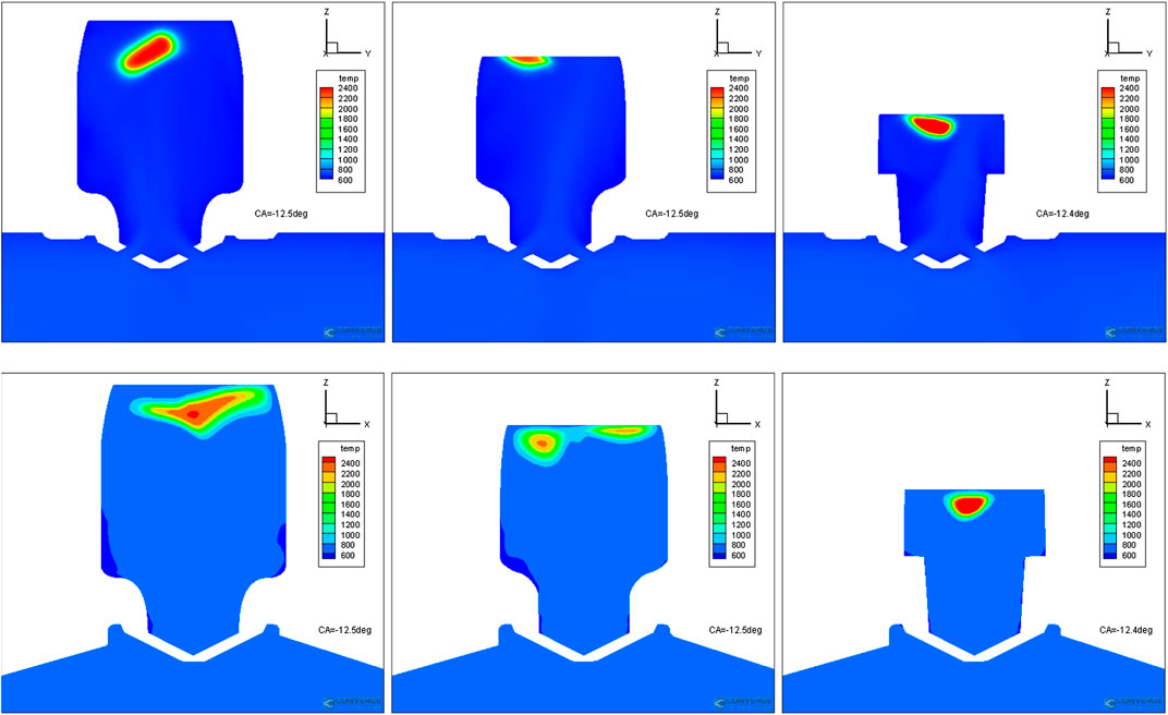
FIGURE 15. Comparison of temperature distributions of designs SVM67 (left), DOE56 (middle), and RegTree64 (right) at −12.5° ATDC. Top row: x-slice. Bottom row: y-slice.
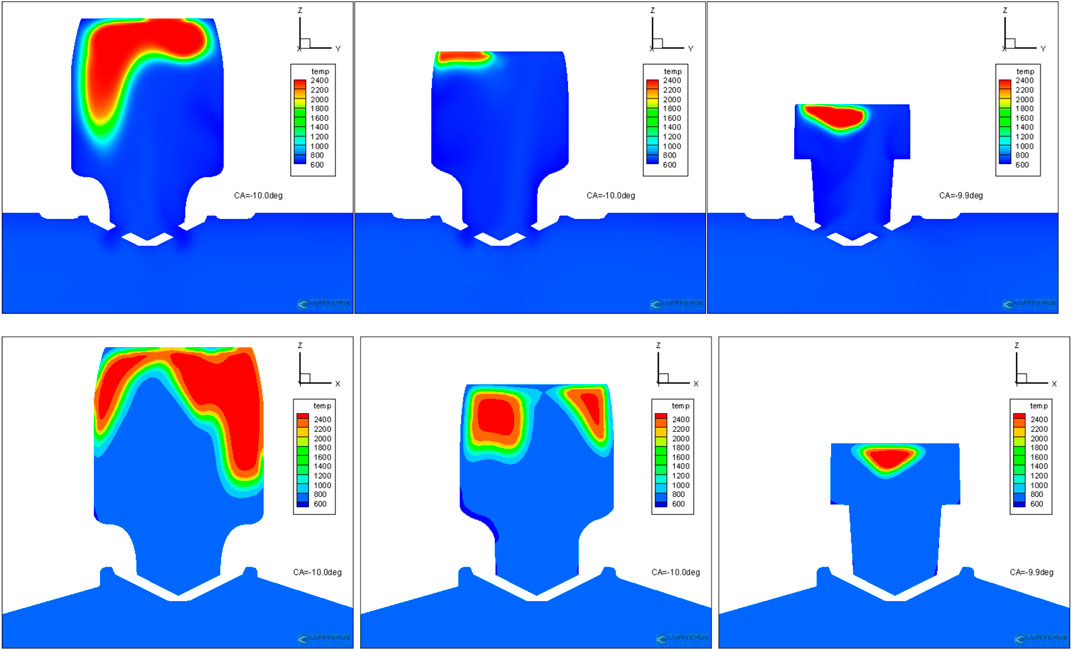
FIGURE 16. Comparison of temperature distributions of designs SVM67 (left), DOE56 (middle), and RegTree64 (right) at −10° ATDC. Top row: x-slice. Bottom row: y-slice.
Regression analysis is conducted to reveal how the design parameters influence the objective, which is the CA50 in the present study. Figures 17 and 18 shows the correlations between CA50 and all the design parameters. Higher coefficient of determination (R2) indicates stronger correlations. Thus, it can be concluded that the design parameters “cr,” “er,” and “ez” are the most evident impacts on the CA50. The parameters “cr” (largest radius, equal to “cr” times the radius at Point E) and “er” (radius at the top of pre-chamber) determine the radii of upper and lower parts of the pre-chamber, respectively. Parameter “ez” determines the height of the pre-chamber. Their negative slopes indicate that greater radius and/or height reduces the CA50, i.e., faster combustion. This is consistent with the previous combustion analysis that larger volume benefits ignition process. The pre-chamber has a roughly cylindrical shape. Its volume mainly depends on the radius and height. This explains why these three parameters have relatively more consistent impacts on the CA50. Since the volume is proportional to square of radius, the slopes of “cr” and “er” is larger than the parameter “ez”. But since the radius depends on both “cr” and “er,” the resulting coefficients of determination of these two parameters are lower than “ez”. The design parameter “θ” determines the slope between the upper part and lower part of the pre-chamber. Larger theta leads to steeper slope. The correlation shows that a steep slope is preferred for better engine performance. Its relatively coefficient of determination implies strong interactions with other design parameters. The parameters that determine the heights of the pre-chamber, “cz,” “dz,” “hz,” “gz,” and “bz,” shows weak correlations with the CA50 based on their low coefficients of determination.
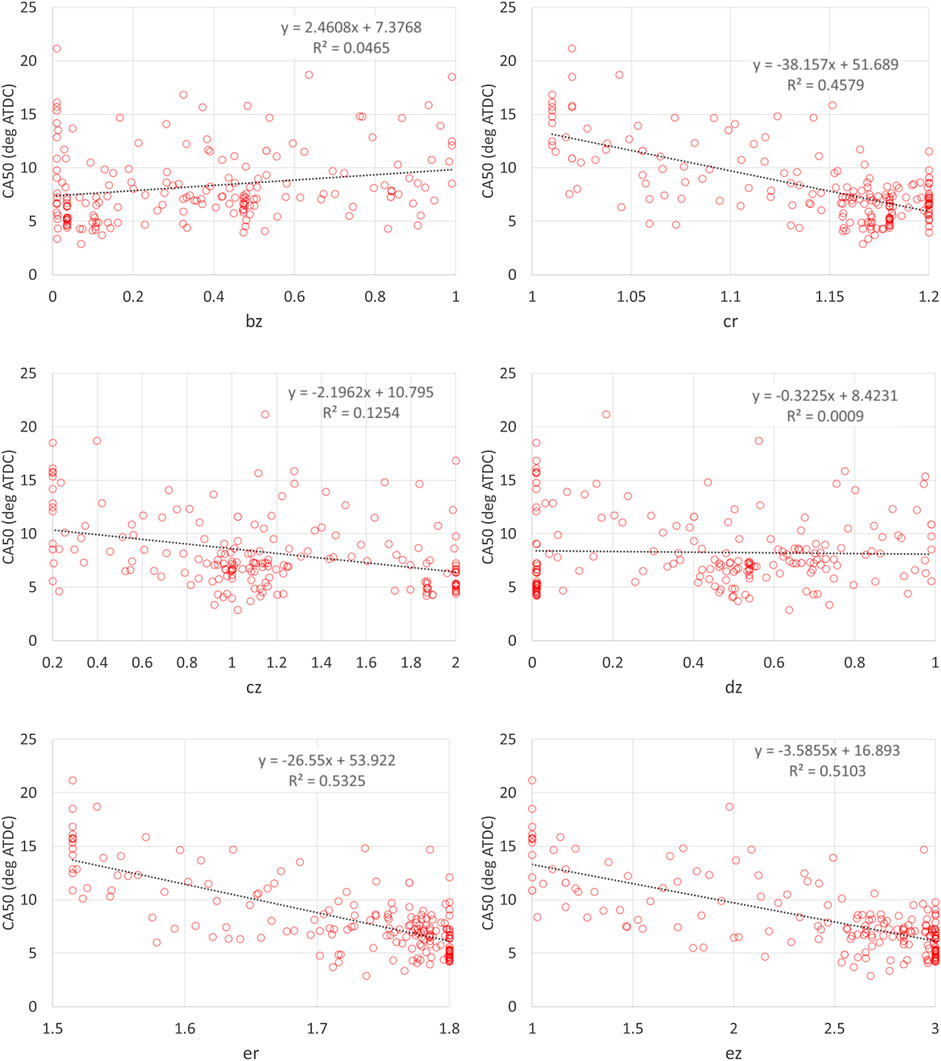
FIGURE 17. Correlations between CA50 and design parameters (bz, cr, cz, dz, er, and ez).
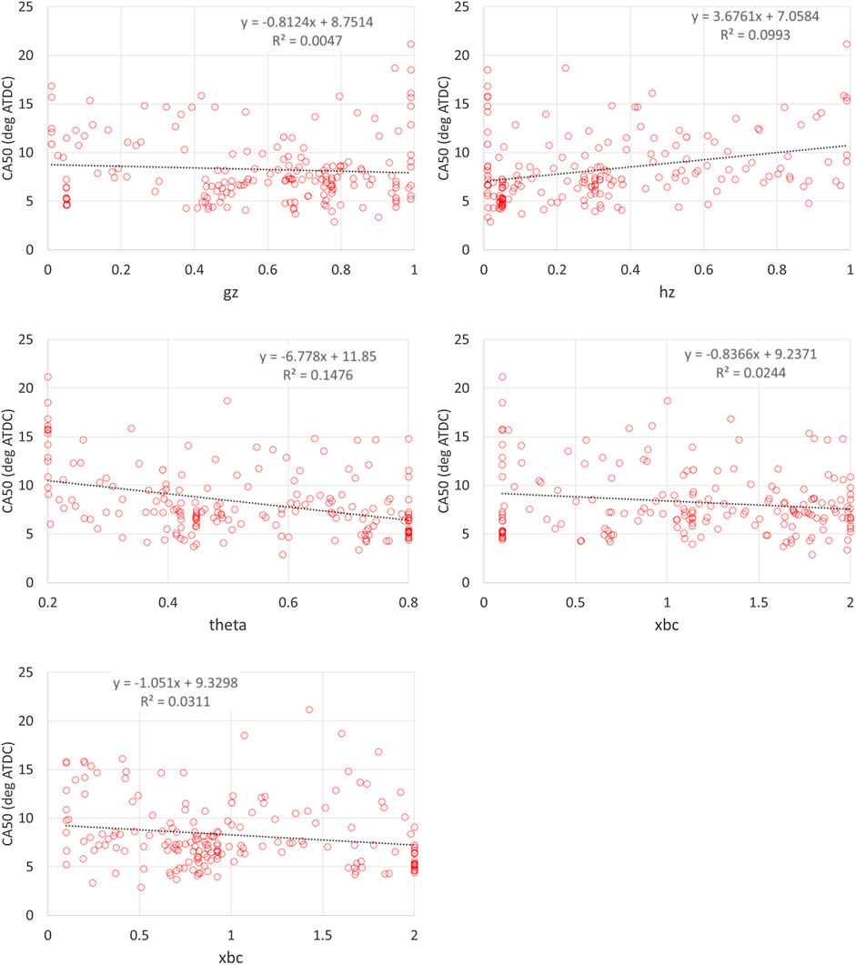
FIGURE 18. Correlations between CA50 and design parameters (gz, hz, theta, xbc, and xde).
The parameters “xbc” and “xde” determine the curvatures around the corners. Their influences are relatively negligible. The present finding is consistent with the observation in Shah et al. (2015) that larger pre-chamber volume benefits the pre-chamber ignition process. For engine combustion, usually the thermodynamics is the most dominant factor. With everything else kept as the same, larger pre-chamber volume results in lower compression ratio that will usually reduce engine efficiency and slow down combustion due to lower in-cylinder temperature and pressure at spark timing. The present application shows that there is competition in the effects of thermodynamics and fluid dynamics on pre-chamber engine combustion. Under certain condition, the fluid dynamics could overtake the thermodynamics to be the most dominant factor for pre-chamber engine combustion. The thermodynamics may become the most dominant factor if the volume of pre-chamber exceeds certain limit. When the volume of pre-chamber is too large, it will lead to low CR, excessive heat loss in pre-chamber (Hua et al., 2021), and weak hot jet issuing into the main chamber. Under this circumstance, the CR should be fixed during the optimization of pre-chamber geometry to isolate its effects.
To avoid potential bias in linear regression analysis, bootstrapping resampling method is conducted. The total 184 data points are randomly resampled for 1,000 times and linear regression analysis is applied to each sampling. Figure 19 shows the scatter plot of slope and coefficient of determination (RSQ) of all the design parameters calculated from the 1,000 times bootstrapping. The results show the same trend as the ones in Figures 17 and 18 in terms of slope and coefficient of determination. The parameters “cr,” “er,” and “ez” have the greatest coefficient of determination. It implies that the previous linear regression analysis is sufficient to compare the relative importance of different design parameters on engine performance. The results of fit linear regression model are provided in the Supplementary Material.
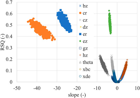
FIGURE 19. Slope and coefficient of determination (RSQ) of all the design parameters of 1,000 times bootstrapping.
In this work, an efficient optimization method that is based on Bayesian updating strategy is developed for 3D CFD-based optimization of internal combustion engines. The method couples DOE, genetic algorithm, and machine learning method. The method is applied to optimize the pre-chamber design for a spark-ignition engine. The pre-chamber geometry is parameterized by 11 design parameters. CA50 is taken as the primary objective of the optimization. A DOE matrix of these design parameters is generated. The designs in the DOE matrix are simulated using 3D combustion CFD, which generates a database that is used to train the machine learning models. Different machine learning models are evaluated in two stages. The first stage is based on the RMSE of the machine learning models. The second stage is based on the iterations with genetic algorithm and 3D combustion CFD. The optimal design is compared with an averaged design to understand the effects of pre-chamber design on engine performance. The following conclusions can be drawn from the present paper:
1) The proposed Bayesian updating optimization method based on 3D combustion CFD, parameterization, DOE, GA, and machine learning is efficient and feasible for engine development.
2) The medium Gaussian SVM model is found to be the best machine learning model in the Matlab for the present application.
3) Combustion analysis of selected designs showed that the turbulent intensity and flow structure inside the pre-chamber is critical for the spark ignition process. Larger volume of the pre-chamber leads stronger jet flow into the pre-chamber, and consequently stronger turbulence and downward flow that speeds up the processes of ignition and flame propagation.
4) Simple linear regression analysis was conducted. The results show that the radius and height of the pre-chamber have evident impact on the CA50. These are the three primary design parameters determining the volume of the pre-chamber. Large radius of the upper part of pre-chamber benefits the ignition process. The heights of the pre-chamber show less influential on engine performance. Steep slope between the upper part and lower part of the pre-chamber is beneficial for the ignition process.
4) Larger volume of pre-chamber leads to lower compression ratio, lower pressure and temperature at the spark timing, and higher residual concentration in the pre-chamber, all of which is not favorable for faster ignition/combustion. Thus, thermochemical conditions conflict with the fluid dynamic conditions. Selecting the right design is to find a sweet spot that compromises these two different mechanisms.
In the future, more design parameters, including nozzle hole number, nozzle hole size, nozzle hole direction, nozzle hole orientation, spark timing, and piston bowl will be taken into consideration. Wider ranges of the design parameters should be explored. The geometry of spark plug needs to be included into the CFD model. More objectives (e.g., CA10, TKE and residual gas fraction of pre-chamber, emissions) and constraints (e.g., peak pressure, peak pressure rising rate) may be taken into account using multi-objective optimization methods.
The raw data supporting the conclusions of this article will be made available by the authors, without undue reservation.
HG and PZ made equal contributions to the present paper.
The authors declare that the research was conducted in the absence of any commercial or financial relationships that could be construed as a potential conflict of interest.
The authors acknowledge the support of Convergent Science Inc. to this research by providing the free academic license of CONVERGE. The authors acknowledge the High-Performance Computing Center (HPCC) at Texas Tech University at Lubbock for providing HPC resources that have contributed to the research results reported within this paper. The authors acknowledge the reviewers for their valuable comments.
The Supplementary Material for this article can be found online at: https://www.frontiersin.org/articles/10.3389/fmech.2020.599752/full#supplementary-material.
Akhtar, M. S., Sun, S., Ma, X., Shen, Y., Shuai, S-J., and Wang, Z. (2017). Effect of the pre-chamber orifice geometry on ignition and flame propagation with a natural gas spark plug. SAE Technical Paper 2017-01-2338. doi:10.4271/2017-01-2338
Alvarez, C. E. C., Couto, G. E., Roso, V. R., Thiriet, A. B., and Valle, R. M. (2018). A review of prechamber ignition systems as lean combustion technology for SI engines. Appl. Therm. Eng. 128, 107–120. doi:10.1016/j.applthermaleng.2017.08.118
Attard, W. P., Fraser, N., Parsons, P., and Toulson, E. (2010). A turbulent jet ignition pre-chamber combustion system for large fuel economy improvements in a modern vehicle powertrain. SAE Int. J. Eng. 3, 20–37. doi:10.4271/2010-01-1457
Attard, W. P., and Parsons, P. (2010). Flame kernel development for a spark initiated pre-chamber combustion system capable of high load, high efficiency and near zero NOx emissions. SAE Int. J. Eng. 3, 408–427. doi:10.4271/2010-01-2260
Badra, J., khaled, F., Sim, J., Pei, Y., Viollet, Y., Pal, P., et al. (2020). Combustion system optimization of a light-duty GCI engine using CFD and machine learning. SAE Technical Paper 2020-01-1313. doi:10.4271/2020-01-1313
Benekos, S., Frouzakis, C. E., Giannakopoulos, G. K., Bolla, M., Wright, Y. M., and Boulouchos, K. (2020). Prechamber ignition: an exploratory 2-D DNS study of the effects of initial temperature and main chamber composition. Combust. Flame 215, 10–27. doi:10.1016/j.combustflame.2020.01.014
Biswas, S., and Qiao, L. (2018). Ignition of ultra-lean premixed H2/air using multiple hot turbulent jets generated by pre-chamber combustion. Appl. Therm. Eng. 132, 102–114. doi:10.1016/j.applthermaleng.2017.11.073
Biswas, S., and Qiao, L. (2016). Prechamber hot jet ignition of ultra-lean H2/air mixtures: effect of supersonic jets and combustion instability. SAE Int. J. Eng. 9, 1584–1592. doi:10.4271/2016-01-0795
Biswas, S., Tanvir, S., Wang, H., and Qiao, L. (2016). On ignition mechanisms of premixed CH4/air and H2/air using a hot turbulent jet generated by pre-chamber combustion. Appl. Therm. Eng. 106, 925–937. http://doi.org/10.1016/j.applthermaleng.2016.06.070
Bolla, M., Shapiro, E., Tiney, N., Kyrtatos, P., Kotzagianni, M., and Boulouchos, K. (2019). Numerical simulations of pre-chamber combustion in an optically accessible RCEM. SAE Technical Paper 2019-01-0224. doi:10.4271/2019-01-0224
Breiman, L., Friedman, J., Stone, C. J., and Olshen, R. A. (1984). Classification and regression trees. Boca Raton: CRC Press.
Dahms, R. N., Chen, J. H., Nguyen, T., and Rieth, M. (2019). “Model development of fundamental combustion processes,” in DOE Vehicle Technologies Office Annual Merit Review Meeting.
Enright, M. P., and Frangopol, D. M. (1999). Condition prediction of deteriorating concrete bridges using Bayesian updating. J. Struct. Eng. 125, 1118–1125.
Freeman, C., Endres, J., Robinson, J., Parameswaran, S., Ge, H., and Zhao, P. (2020). CFD-guided development of a pre-chamber ignition system for internal combustion engines. Int. J. Powertrains 11, 23–27. doi:10.1515/9783486736366-027
Ge, H. W., Lee, C. W., Shi, Y., Reitz, R. D., and Willems, W. (2011). Coupling of scaling laws and computational optimization to develop guidelines for diesel engine down-sizing. SAE Technical Paper 2011-01-0836. doi:10.4271/2011-01-0836
Ge, H. W., Shi, Y., Reitz, R. D., Wickman, D., and Willems, W. (2010). Engine development using multi-dimensional CFD and computer optimization. SAE Technical Paper 2010-01-0360. doi:10.4271/2010-01-0360
Ge, H. W., Shi, Y., Reitz, R. D., Wickman, D. D., and Willems, W. (2009). Optimization of a HSDI diesel engine for passenger cars using a multi-objective genetic algorithm and multi-dimensional modeling. SAE Int. J. Eng. 2, 691–713. doi:10.4271/2009-01-0715
Ge, H. W., Shi, Y., Reitz, R. D., and Willems, W. (2010). Optimization of a HSDI diesel engine at low-load operation using a multi-objective genetic algorithm and detailed chemistry. Proc. Inst. Mech. Eng. Part D J. Automob. Eng. 224, 547–563. doi:10.1243/09544070JAUTO1351
Gentz, G., Thelen, B., Gholamisheeri, M., Litke, P., Brown, A., Hoke, J., et al. (2015). A study of the influence of orifice diameter on a turbulent jet ignition system through combustion visualization and performance characterization in a rapid compression machine. Appl. Therm. Eng. 81, 399–411. doi:10.1016/j.applthermaleng.2015.02.026
Gentz, G. R., and Toulson, E. (2016). Experimental studies of a liquid propane auxiliary fueled turbulent jet igniter in a rapid compression machine. SAE Int. J. Eng. 9, 777–785. doi:10.4271/2016-01-0708
Gholamisheeri, M., Wichman, I. S., and Toulson, E. (2017). A study of the turbulent jet flow field in a methane fueled turbulent jet ignition (TJI) system. Combust. Flame, 183, 194–206. doi:10.1016/j.combustflame.2017.05.008
Han, Z., and Reitz, R. D. (1995). Turbulence modeling of internal combustion engines using RNG κ–ε models. Combust. Sci. Technol. 106, 267–295. doi:10.1080/00102209508907782
Hlaing, P., Echeverri Marquez, M., Singh, E., Almatrafi, F., Cenker, E., Ben Houidi, M., et al. (2020). Effect of pre-chamber enrichment on lean burn pre-chamber spark ignition combustion concept with a narrow-throat geometry. SAE Technical Paper 2020-01-0825. doi:10.4271/2020-01-0825
Hua, J., Zhou, L., Gao, Q., Feng, Z., and Wei, H. (2021). Influence of pre-chamber structure and injection parameters on engine performance and combustion characteristics in a turbulent jet ignition (TJI) engine. Fuel 283, 119236. doi:10.1016/j.fuel.2020.119236
Karimi, A., Rajagopal, M., and Nalim, R. (2014). Traversing hot-jet ignition in a constant-volume combustor. J. Eng. Gas Turbines Power, 136, 041506. doi:10.1115/1.4025659
Kim, J., Scarcelli, R., Som, S., Shah, A., Biruduganti, M. S., and Longman, D. E. (2019). “Assessment of turbulent combustion models for simulating pre-chamber ignition in a natural gas engine,” in ASME ICED fall technical conference, pp. V001T06A12. doi:10.1115/ICEF2019-7278
Kodavasal, J., Abdul Moiz, A., Ameen, M., and Som, S. (2018). Using machine learning to analyze factors determining cycle-to-cycle variation in a spark-ignited gasoline engine. J. Energy Resour. Technol. 140, 13–19. doi:10.1115/1.4040062
Launder, B. E., and Spalding, D. B. (1974). The numerical computation of turbulent flows. Comput. Methods Appl. Mech. Eng. 3, 269–289.
Lee, C. W., Ge, H. W., Reitz, R. D., Kurtz, E., and Willems, W. (2012). Computational optimization of a down-scaled diesel engine operating in the conventional diffusion combustion regime using a multi-objective genetic algorithm. Combust. Sci. Technol. 184, 78–96. doi:10.1080/00102202.2011.620051
Li, F., Zhao, Z., Wang, B., and Wang, Z. (2020). Experimental study of pre-chamber jet ignition in a rapid compression machine and single-cylinder natural gas engine. Int. J. Engine Res. 146, 47–53. doi:10.1177/1468087419883783
Liu, Y-D., Jia, M., Xie, M-Z., and Pang, B. (2012). Enhancement on a skeletal kinetic model for primary reference fuel oxidation by using a semidecoupling methodology. Energy Fuels 26, 7069–7083. doi:10.1021/ef301242b
Lu, T., and Law, C. K. (2008). A criterion based on computational singular perturbation for the identification of quasi steady state species: a reduced mechanism for methane oxidation with NO chemistry. Combust. Flame 154, 761–774. doi:10.1016/j.combustflame.2008.04.025
Mastorakos, E., Allison, P., Giusti, A., De Oliveira, P., Benekos, S., Wright, Y., et al. (2017). Fundamental aspects of jet ignition for natural gas engines. SAE Int. J. Eng. 10, 2429–2438. doi:10.4271/2017-24-0097
Moiz, A. A., Pal, P., Probst, D., Pei, Y., Zhang, Y., Som, S., et al. (2018). A machine learning-genetic algorithm (ML-GA) approach for rapid optimization using high-performance computing. SAE Int. J. Comm. Veh. 11, 291–306. doi:10.4271/2018-01-0190
Muller, M., Freeman, C., Zhao, P., and Ge, H. (2018). “Numerical simulation of ignition mechanism in the main chamber of turbulent jet ignition system,” in ASME ICED fall technical conference. doi:10.1115/icef2018-9587
Probst, D. M., Raju, M., Senecal, P. K., Kodavasal, J., Pal, P., Som, S., et al. (2019). Evaluating optimization strategies for engine simulations using machine learning emulators. J. Eng. Gas Turbines Power, 141, 124–129. doi:10.1115/1.4043964
Richards, K., Senecal, P., and Pomraning, E. (2017). CONVERGE 2.4 manual. Madison, WI: Convergent Science, Inc.
Ronchetti, E., Field, C., and Blanchard, W. (1997). Robust linear model selection by cross-validation. J. Am. Stat. Assoc. 92, 1017–1023. doi:10.2307/2965566
Shah, A., Tunestal, P., and Johansson, B. (2015). Effect of pre-chamber volume and nozzle diameter on pre-chamber ignition in heavy duty natural gas engines. SAE Technical Paper 2015-01-0867. doi:10.4271/2015-01-0867
Shah, N., Zhao, P., DelVescovo, D., and Ge, H. (2019). Prediction of autoignition and flame properties for multicomponent fuels using machine learning techniques. SAE Technical Paper 2019-01-1049. doi:10.4271/2019-01-1049
Shi, Y., Ge, H. W., and Reitz, R. D. (2011). Computational optimization of internal combustion engines. London: Springer. doi:10.1007/978-0-85729-619-1
Tang, Q., Sampath, R., Marquez, M. E., Hlaing, P., Sharma, P., Ben, M., et al. (2008). Simultaneous negative PLIF and OH* chemiluminescence imaging of the gas exchange and flame jet from a narrow throat pre-chamber. SAE Technical Paper 2020-01-2080, (2020). doi:10.4271/2020-01-2080
Ting, K. M., and Witten, I. H. (2020). Stacking bagged and dagged models. New Zealand: Hamilton Press.
Toulson, E., Huisjen, A., Chen, X., Squibb, C., Zhu, G., Schock, H., et al. (2012). Visualization of propane and natural gas spark ignition and turbulent jet ignition combustion. SAE Int. J. Eng. 5, 1821–1835. doi:10.4271/2012-32-0002
Toulson, E., Schock, H. J., and Attard, W. P. (2010). A review of pre-chamber initiated jet ignition combustion systems. SAE Technical Paper 2010-01-2263. doi:10.4271/2010-01-2263
Williams, C. K., and Rasmussen, C. E. (2006). Gaussian processes for machine learning. Cambridge, MA: MIT Press.
Xu, Z., Dai, M., and Meng, D. (2009). Fast and efficient strategies for model selection of Gaussian support vector machine. IEEE Trans Syst Man Cybern B Cybern, 39, 1292–307. doi:10.1109/TSMCB.2009.2015672
Keywords: pre-chamber, CFD, genetic algorithm, design of experiment, machine learning, medium Gaussian SVM model, Bayesian updating, turbulent jet ignition
Citation: Ge H, Bakir AH, Yadav S, Kang Y, Parameswaran S and Zhao P (2021) CFD Optimization of the Pre-Chamber Geometry for a Gasoline Spark Ignition Engine. Front. Mech. Eng. 6:599752. doi: 10.3389/fmech.2020.599752
Received: 28 August 2020; Accepted: 16 November 2020;
Published: 25 January 2021.
Edited by:
Yuanjiang Pei, Aramco Services Company, United StatesReviewed by:
Weiqi Ji, Massachusetts Institute of Technology, United StatesCopyright © 2021 Ge, Bakir, Yadav, Kang, Parameswaran and Zhao. This is an open-access article distributed under the terms of the Creative Commons Attribution License (CC BY). The use, distribution or reproduction in other forums is permitted, provided the original author(s) and the copyright owner(s) are credited and that the original publication in this journal is cited, in accordance with accepted academic practice. No use, distribution or reproduction is permitted which does not comply with these terms.
*Correspondence: Haiwen Ge, aGVhdmVuZ2VyY0BnbWFpbC5jb20=, aGFpd2VuLmdlQHR0dS5lZHU=; Peng Zhao, cGVuZ3poYW9Ab2FrbGFuZC5lZHU=
†These authors have contributed equally to this work
Disclaimer: All claims expressed in this article are solely those of the authors and do not necessarily represent those of their affiliated organizations, or those of the publisher, the editors and the reviewers. Any product that may be evaluated in this article or claim that may be made by its manufacturer is not guaranteed or endorsed by the publisher.
Research integrity at Frontiers
Learn more about the work of our research integrity team to safeguard the quality of each article we publish.