- Department of Mechanical Engineering, Bucknell University, Lewisburg, PA, United States
An assumption of constant discharge coefficient (Cd) is often made when modeling highly compressible pulsating engine flows through valves or other restrictions. Similarly, orifices and flow-nozzles used for real-time EGR flow estimation are often calibrated at a few steady-state points with one single constant Cd that minimizes the error over the selected points. This quasi-steady assumption is based on asymptotically constant Cd observed at high Reynolds number for steady (non-pulsating) flow. It has been shown in this work that this assumption is not accurate for pulsating flow, particularly at large amplitudes and low flow rates. The discharge coefficient of a square-edged orifice placed in the exhaust stream of a diesel engine produced Cd's varying between 0.60 and 0.90 for critical/near-critical flows. A novel pulsating flow measurement apparatus that allowed independent variation of pressure, flow rate and frequency and allowed reproducible measurements independent of transducer characteristics, produced Cd's in the range of 0.25–0.60 with a similar square-edge orifice. The variation in Cdwas found to be correlated to two dimensionless variables, η and ξ, defined as the standard deviation of the pulsating pressure signal, σΔp, normalized by and across the orifice, respectively. The results suggest that many aspects of compressible pulsating flow through flow restrictions are yet to be understood.
Background, Motivation, and Existing Literature
While trying to determine the root cause of smoke spikes in electronically controlled diesel engines, previous work by the author and co-workers have found that the flow-nozzle based EGR flow estimate as well as the Volumetric Efficiency estimate can be significantly inaccurate during the turbocharger lag period (Brahma, 2011, 2013, 2014). The inaccurate estimation of in-cylinder Oxygen mass was responsible for the smoke/particulate matter spikes. The ECM estimates were based on the flow resistance of the EGR valve, EGR flow measurement flow-nozzle, engine intake/exhaust valves and the plumbing of the air-handling system. These investigations suggested the possibility that the flow resistance of flow restrictions, assumed constant at high flow rates/Reynolds numbers, might be a variable for the highly compressible pulsating flows encountered within engines, dependent on the pulsating pattern. The simplest way of investigating this possibility was to measure the discharge coefficient (Cd) of an orifice located in pulsating flow. A preliminary study investigating the Cdof a square-edged orifice installed in the exhaust stream of a diesel engine found that Cdkept increasing with Reynold's numbers exceeding 10,000 for steady pulsating flow (Brahma et al., 2014). Steady-flow Cd′s are asymptotically constant beyond that Re. The current work was initiated as a result of these observations.
The five engine operating conditions in the preliminary work were expanded to 105 steady state data points for the current work. The engine pulsation parameters were correlated, e.g., pulsation amplitude increased with flow rate. To separate causative factors, a pulsating flow apparatus was constructed in which each factor could be independently varied. This allowed a systematic investigation of dimensionless groups that might be correlated with flow resistance.
A brief theoretical/historical background of steady-flow Cd and its direct application to pulsating flow is provided below. This is followed by a review of the literature addressing Cd measurement in pulsating flow. The literature on pulsating flow resistance has historically focused on sources of error when applying steady-flow knowledge to unsteady flow situations. Based on the literature and current work, the quasi-static assumption appears to be the biggest source of error. This assumption has also been questioned in related areas such as pulsatile pipe flow and the modeling of turbocharger performance; related literature has been discussed.
The discharge coefficient of an orifice or nozzle is defined as the ratio of the actual to theoretical flow rate:
The theoretical flow rate ṁtheoretical for steady compressible flow through an orifice or nozzle is given by Fluid Meters (1971a):
Subscripts “1” and “2” refer to upstream and downstream conditions, respectively, p is the pressure, ρ is density, k is the specific heat ratio for the gas and A is the flow area. Equation (2) can be derived by assuming isentropic expansion through the restriction, and applying conservation laws of mass and energy. The discharge coefficient Cd accounts for friction, heat transfer, boundary layer thickness and the approximation that properties measured downstream of the orifice or nozzle exit represent the conditions at the exit.
The theoretical flow rate can also be calculated by incorporating a theoretical or empirical “compressibility factor” Y in the incompressible orifice equation derived by applying the Bernoulli's equation across an orifice (Fluid Meters, 1971a):
The theoretical compressibility factor can be obtained by re-writing Equation (2) in the form of Equation (3).
The ASME research committee on flow meters first documented empirical equations and tables for Cd for a variety of orifices, nozzles and nozzle-venturi devices in 1924, and continued updating results till it produced the sixth edition in 1971 (Fluid Meters, 1971a). An empirical equation for Cd for a square-edged orifice in steady flow with flange taps for pressure measurement was used in the current work (Fluid Meters, 1971b). The report recommends damping out any pulsations prior to compressible flow measurement, based on the work of Sparks (1966), who found no relationship between the average differential pressure and the average velocity of pulsating air-flow through an orifice. The report recommends using surge bottles and pulsation dampeners according to the design recommendations of Chilton and Handley (1952). However, this is not always a practical proposition for internal combustion engines. Exhaust Gas Recirculation (EGR) measurement is often based on differential pressure measurement of pulsating exhaust gases. The current industrial practice is to assume that the discharge coefficient of the orifice/flow nozzle is constant at the high Reynolds numbers encountered in the EGR loop, and to experimentally determine Cd in a test cell by running the engine at select steady-state operating conditions. This assumption is based on the data in the ASME report originating in the work by Bean et al. (1929), as well as work on viscous liquids by Tuve and Sprenkle (1933). The data was collected for steady-state, no-pulsating flows. Similarly, it is common practice to model engine flows, e.g., through intake and exhaust valves, using Cdvalues determined from non-pulsating data. For example, the commonly used engine modeling software, “GT-Power,” uses discharge coefficients based on the work of Lichtarowicz et al. (1965), for modeling pulsating flow through all flow restrictions such as valves and orifices, using a quasi-static assumption. The current work demonstrates that the quasi-static assumption is incompatible with the range of pulsating Cd's measured for many flow conditions. For example many pulsating measurements at high pressure and low flow rates were in the range 0.25–0.40, well outside the range of 0.60–0.62 if quasi-static assumptions were applied to these flow conditions for the particular orifice used.
The existing literature on discharge coefficients in pulsating flow does not offer a solution to the practical problems mentioned above; rather it allows a better understanding of the problem. It discusses four main aspects, mainly in the context of the incompressible flow using Equation (3).
a. Square Root Error: The error associated with averaging the pulsating differential pressure signal rather than averaging the square root of Δp.
b. Measurement Errors due to acoustic effects arising in the pressure lines and fittings leading to the differential pressure transducer. Slow response transducers and aliasing could compound this problem.
Square root errors, acoustic effects and aliasing are well-understood, e.g., Nakamura et al. (2005) and González et al. (2016) have resolved these errors when using Pitot tubes to measure flow rate at the exhaust tailpipe.
c. Error due to neglecting the temporal inertia term: The unsteady Bernoulli's equation across an orifice can be integrated (along the direction of flow) to obtain the following equation, valid at any instant, for incompressible, inviscid flow (Doblhoff-Dier et al., 2011):
where C1 and C2 are constants calculated from the geometry of the orifice and measurement setup. The second term on the right-hand-side is the temporal inertia term that accounts for the convective acceleration of the flow along the streamline, as a result of increasing pressure of the pressure pulse. The term is zero for non-pulsating flow, in which case Equation (4) reduces to Equation (3), with C1 encompassing both Cd and Y to accommodate viscous, compressible flows. For pulsating flow, since part of the pressure differential is used to accelerate the flow, neglecting the inertial term can result in overestimation of Cd.
In their 1991 review paper, Gajan et al. (1992) have reported that the inertial error increases with frequency (Strouhal number) and amplitude, and cannot be ignored; errors up to 25% have been reported (see Figure 3 of their paper). Doblhoff-Dier et al. have examined this question in a more recent 2011 paper (Doblhoff-Dier et al., 2011) and found that the inertial term can only be ignored if the ratio of the pulsating velocity component to the product of frequency and orifice diameter exceeds 10. Most of the data presented in this work exceeded that ratio, ranging between 1 and 200. Note that Equation (4) was derived from incompressible assumptions and a simple inertial term cannot be derived for compressible flows. Doblhoff-Dier et al. were able to ignore compressibility effects for their experimental setup, but since the density change across the orifice was quite significant for the engine data presented in this work (up to 100%), the inertial term of Equation (4) might not represent most engine flows.
d. Quasi-Static Assumption: All of the above assume that the Cd of pulsating flow is identical to that of steady state flow (quasi-static assumption), and accurate metering of pulsating flow can occur if there exists no square-root and measurement errors and inertia of the accelerating flow is accounted for. However, as pointed out by Doblhoff-Dier et al., many researchers (Gajan et al., 1992; Mottram, 1992; ISO, 1998) believe that pulsating Cd (and therefore C1 in Equation 4) is different from steady state Cd, owing to differences in boundary layer thickness and flow structures in the separation zone. Gajan et al. (1992) have said that “the biggest gap in our knowledge of pulsation effects on flow through an orifice is probably the variation of the discharge coefficient with various pulsation and acoustic parameters in a given flow system.” They have described work performed at CERT/ONERA (France) where it was found that the plateau shaped velocity profile at the exit of the orifice disappeared faster in the free stream direction for pulsating flow relative to steady flow, i.e., diffusion of momentum was increased by flow pulsation. Variations in Cd were observed to increase with amplitude of pulsation, but could not be correlated to any particular variable, e.g., Strouhal number. Similar variations in pulsating Cdhave been reported by Reis and Hanriot (2017), very recently for low Reynolds number pulsating liquid flow. Deviation of Cd from steady state values in accelerating and de-accelerating flows have been studied as early as 1951 (Daily et al., 1955).
In addition, substantial literature on pulsating flow through pipes (not orifices) exists, and the effect of oscillations on flow structure, boundary layer and shear-stress is a sub-field in itself, see for example relatively recent highly cited work by He and Jackson (2009), or review papers by Gundogdu and Carpinlioglu (1999a), Gundogdu and Carpinlioglu (1999b), Çarpinlioglu and Gündogdu (2001), Iguchi and Ohmi (1982), Ohmi et al. (1982), or Ahn and Ibrahim (1992).
These investigations are inconsistent with the quasi-static assumption and so are the results presented in this work. According to the quasi-static assumption, for the particular orifice installation and range of Reynolds numbers tested, all Cd's should be within a narrow range between 0.60 and 0.62, owing to asymptotic behavior at high Reynolds number. But most of the pulsating measurements were outside that range, and high pressure-low flow conditions produced Cd's in the range of 0.25–0.40. No combination of instantaneous quasi-static Cd's exceeding 0.60 can result in and average Cd below 0.40. The inertial term is too small to explain this discrepancy. For all the data points in this work, Inertial force was a small fraction of the total pressure force driving the flow (<0.2%). For pulsating flow conditions producing low Cd's, most system-level engine simulation packages would overestimate flow rates even if they simulated the wave dynamics accurately, since they generally use the quasi-steady assumption to choose Cd at the predicted instantaneous Reynolds number using steady flow results. For example, GT-Power uses the steady flow results of Lichtarowicz et al. (1965) to assign default (but adjustable) values of discharge coefficients for orifices of various lengths. If the low Cd's for pulsating flow are a result of differences in boundary layer and/or flow structures in the separation zone, they cannot be described by system level models. This is where experimental data such as that generated by this work can be useful. The same argument can be made for on-board EGR flow estimation.
The errors listed above are also encountered when predicting turbocharger performance with maps generated by steady flow (non-pulsating) test benches. But unlike discharge coefficients for pulsating flow, interest in unsteady turbocharger performance has continued to this day, and some insight can be drawn from this body of work. Automotive turbochargers experience pulsating flow outside the laboratory but their performance has historically been characterized by steady flow maps, using the quasi-steady assumption. However, several researchers have found significant deviations in the radial-inflow turbine characteristics under pulsating flow conditions and corresponding quasi-steady predictions (Dale and Watson, 1986). These researchers include Dale and Watson (1986) and Baines et al. (1994) at the Imperial college, Winterbone et al. (1990, 1991) at the University of Manchester, Kosuge et al. (1976) at Keio University in Japan and Capobianco et al. (1989) and Capobianco and Gambarotta (1992) at the University of Genoa in Italy. Most of these investigations have focused on different turbocharger turbines, e.g., single/double entry, mixed flow etc., rather than the compressor presumably because the pulsations are of much larger magnitude at turbine inlet. Kosuge et al. (1976) have reported increasing deviations with pulse frequency and amplitude (both were correlated and the effect of each factor was not studied separately). More recently, Copeland et al. (2011) have found a significant decrease in measured turbine efficiency for high amplitude-low frequency pulsating flow through a double-entry circumferentially divided turbocharger, relative to quasi-steady predictions. They have also summarized the insights gained from the previous works cited above: The emptying and filling of mass and the wave dynamics occurring within the turbine volute/passage determines the flow dynamics for pulsating flow. Further, the pressure fluctuates faster than the mass flow rate. Quasi-steady predictions would neglect these effects. Consequently, Liu and Copeland have recently developed a new method for turbine mapping that uses experimental data generated from a pulse rig (Liu and Copeland, 2018). They have also reported negative turbine power during the trough period of the pulsation. Marelli et al. (2014) have performed similar investigations on turbocharger compressors.
The disagreement between quasi-steady and dynamic behavior for both turbochargers and orifices probably stem from different phenomena. Boundary layer and flow separation differences between steady and pulsating flow might be more important for orifices. The effect of volume capacitance and wave dynamics on mass flow rate might be more important for turbochargers. But it is interesting to note that turbines have been continuously investigated for non-quasi-steady behavior since the 70's but not orifices. In fact, no work could be found in the literature that investigated highly compressible pulsating flows that occur in engines. None of the pulsating orifice works cited above had density changes of the magnitude encountered in engine flows. For the current work, the ratio of upstream to downstream density for the engine data ranged between 1.08 and 1.91. On the other hand, many researchers have investigated highly compressible (critical) but non-pulsating flows (Grace and Lapple, 1951; Jackson, 1963; Kastner et al., 1964; Deckker and Chang, 1965; Rohde et al., 1969; Brain and Reid, 1975; Ward-Smith, 1979).
While there exists a gap in literature, the ubiquitous use of variable geometry turbochargers and high pressure EGR systems have created a need for accurate modeling and estimation of pulsating flows across a wide range of flow conditions. The current work is not aimed at understanding pulsating Cd in engine flows at a fundamental level, but rather to measure and characterize it across a wide range of frequencies, flow rates and pressure, including highly compressible pulsating flows and critical/near-critical pulsating flows that have never been investigated till now. Instead of trying to understand the observed deviation from steady flow Cdin terms convective acceleration and non-quasi-static behavior, attempts have been made to characterize Cdin terms of dimensionless parameters, such that the results are useful for engine modeling and control. In addition, the data can be used by other researchers for fundamental studies that are required to answer some of the questions originating from the results of this work.
Description of Apparatus and Test Plan
A schematic of the engine apparatus is shown in Figure 1, top. An orifice was located in the exhaust stream of a naturally aspirated four-stroke diesel engine. High frequency pressure and temperature measurements were made at and across the orifice. The mass flow rate through the orifice was equal to the reference intake mass flow rate measured with a laminar flow element, plus the fuel flow rate measured with a rotary fuel flow meter. These measurements were used to calculate Cd using Equation (2), for steady-state data points spanning the torque curve, ranging between 40 and 100% throttle position (increment 10%) and 1,000–2,900 RPM (increment 500 RPM). Additionally, a finer RPM sweep with 50 RPM increment was undertaken at 70% throttle position. Data from 51 unique speed-throttle combinations was obtained, and repeated several times. Since the dynamometer used throttle rather than torque control, every throttle repeat produced slightly different fueling. Including the repeats and after discarding data that failed quality checks, 105 unique steady-state points with different mass flow rates were obtained in all. Plots of the operating conditions are available in Figure A1 in Supplementary Material. A detailed description of the engine apparatus used can be found in previous work (Brahma et al., 2014).
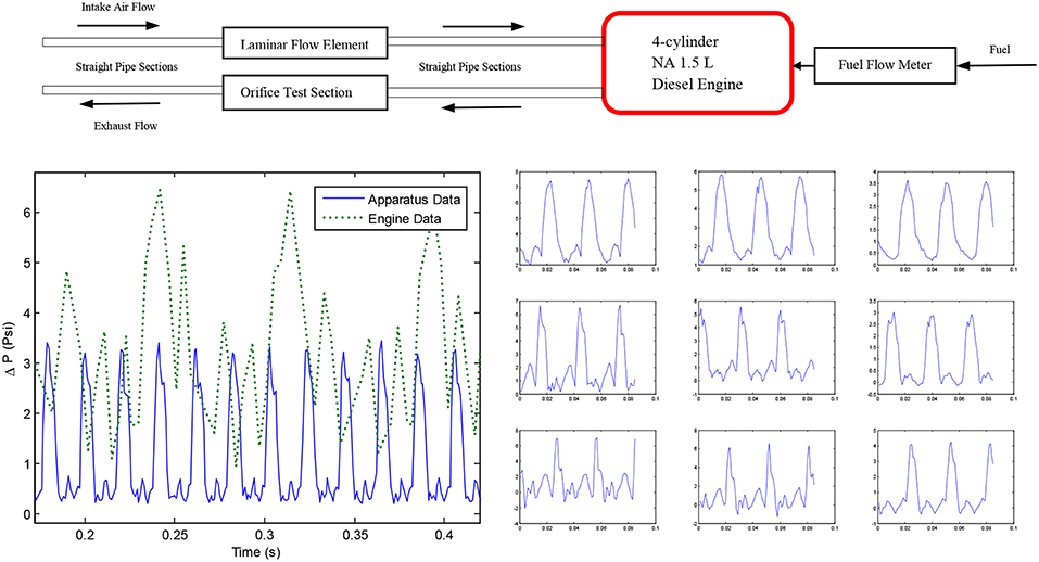
Figure 1. The schematic on the top shows the apparatus used to generate the engine data, details available in Brahma et al. (2014). Bottom plots: Comparison of engine differential pressure pulses (bottom-right) with those generated by the pulsating apparatus (bottom-left). Each engine cycle produced four pulses that were different from each other. Possible reasons are differences in combustion and different interference patterns dependent on the geometry of the exhaust manifold. The pulsating apparatus used a single cylinder compressor to produce consistent pulsations.
The engine data (presented later) was not ideal for investigating dimensionless groups correlated to pulsating Cd. Amplitude, frequency and flow rate were correlated and could not be independently varied. Orifice pressure could not be increased without excess smoke/engine stalling. The pulsations produced by the four cylinders were of unequal magnitude as opposed to consistent pulsations produced by the apparatus, compare Figure 1, bottom left with Figure 2, bottom right.
An apparatus was therefore constructed to obtain consistent pulsations while varying frequency, flow velocity and system pressure independently. These variations also produced differently shaped Δp pulses; the pulsating patterns of nine of the ten repeat points selected for uncertainty analysis are shown in Figure 1 to illustrate this. The pulsating patterns of all of the 189 data points used for this work is available in Figure A2 in Supplementary Material.
A sketch of the pulsating apparatus is shown in Figure 2. Pulsating air is generated by a reciprocating compressor and flows to the test section through a bleed valve (V1) to control mass flow rate and therefore flow velocity. Downstream of the orifice, the orifice pressure valve (V2) controls the system pressure. V1 and V2 are intended to control velocity and pressure independently; in practice it is a multiple input-multiple output (MIMO) system in that system pressure is weakly dependent on V1 and flow velocity is weakly related to the position of V2. After V2, the pulsating flow is cooled to room temperature in a heat exchanger before being sent to a surge tank to remove pulsations prior to the reference Pitot-static tube measurement, made with steady air at room temperature.
The Pitot tube measurement is calibrated with non-pulsating steady flow shop air, which replaces the compressor during shop air calibration. Each component of the apparatus and its justification and evolution is discussed below.
A two horsepower “Makita” brand single cylinder compressor designed for industrial use was used to generate pulsating flow, shown in Figure 3E. It was connected to the main test section with 9.5 mm outer diameter (3/8th inch) copper pipe of length 1,168 mm. In order to vary pulsation frequency, the compressor's single-phase AC motor was replaced by a 3-phase AC motor whose speed was controlled by a variable frequency drive (VFD). A specially machined adapter made this possible. The VFD was used to vary the compressor speed between 1,000 and 3,000 RPM during testing, i.e., between 20 and 50 Hz. For a 4-cylinder engine this frequency range corresponds to 600–1,500 engine RPM while the engine data ranged between 1,000 and 3,000 RPM. The partial overlap of frequency was due to safety reasons. The compressor was built to run at 1,800 RPM only, and running it above 3,000 RPM produced significant vibration and thermal stresses. Pulsation frequency by itself was uncorrelated to Cd (see Figure A3 in Supplementary Material); the main difference between the engine and apparatus data resulted from differences in flow velocities. It will be shown later (by Figure 12) that both datasets can be reconciled with two non-dimensional groupings.
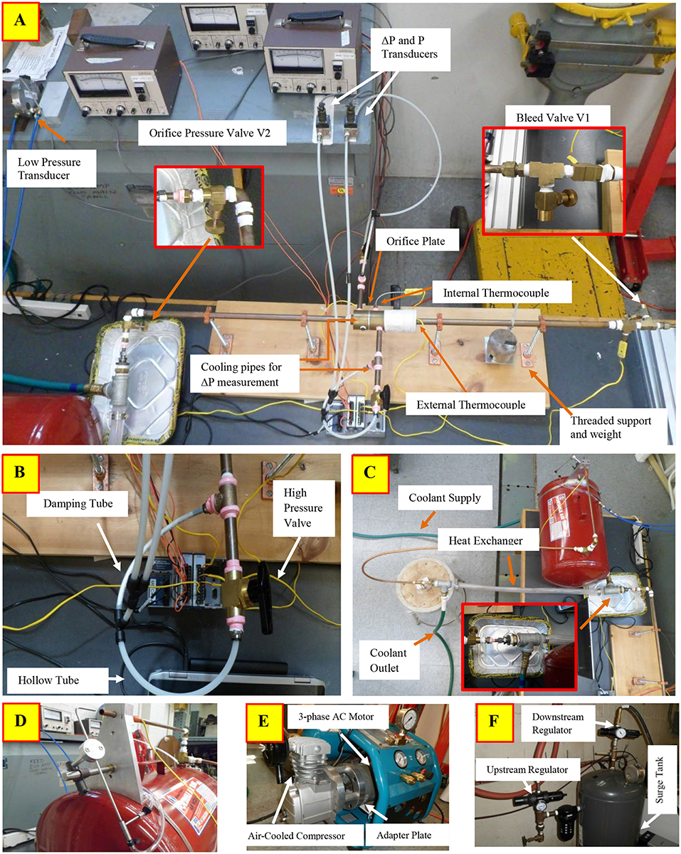
Figure 3. The main test section is shown by the top picture (A). (B) Shows the arrangement to switch between damped and pulsed pressure measurement. (C) Shows the shell-and-tube heat exchanger used to cool the gas prior to the pitot-static reference measurement (D). The compressor used to generate pulsating flow is shown by (E). (F) Shows the surge tank and pressure regulation equipment used to provide steady flow for the shop air calibration process.
Figure 3A shows the main test section. Two 14 mm ID (5/8th inch OD) copper pipes, 559 mm long, were soldered on either side of a hollow brass cylinder bored to the same internal diameter. The brass cylinder was split into two 38 mm sections that were bolted together with the aluminum orifice plate sandwiched in between. The orifice plate was therefore installed between approximately 597 mm straight pipe sections on both sides, corresponding 37 pipe diameters (ASME recommends at least 6 pipe diameters for this kind of installation (Fluid Meters, 1971c). The orifice diameter was 4.2 mm, so the ratio of orifice to pipe ID was 0.30 (d/D or β = 0.30), chosen to be close to the engine data (β = 0.26). Lower β's allow a better comparison between pulsating and non-pulsating flow since non-pulsating Cd shows smaller variation and becomes constant at a lower Red. The other dimensions of the system were selected by matching compressor performance (3.3 CFM at 621 kPa gage pressure) with measurement capabilities, with the selected β.
The concentric square-edged orifice was 3.2 mm thick (1/8th) and machined out of Aluminum according to ASME standards (MFC-3M standards). Flange taps for differential pressure measurement were located 25.4 mm (1 inch) from the orifice plate, and machined onto the brass cylinder. The orifice pressure measurement was teed off the upstream pressure tap. A taps was drilled 12.7 mm (½ inch) upstream of the orifice. An additional temperature surface measurement was made just upstream of the brass cylinder; an external thermocouple was attached with thermocouple tape and wrapped with insulating material (covering part of the brass cylinder in Figure 3A). The flow temperature measurement was used to calculate density; the surface temperature measurement was used for corroboration, to detect bad data.
Two copper pipes and fittings of combined length 222 mm were threaded into the flange taps to cool the gas by natural convection prior to the Δp measurement, to maintain the transducer at room temperature and prevent thermal drift. The transducers were laboratory grade variable reluctance transducers with interchangeable diaphragms to adjust range: Validyne Model DP 15 for orifice Δp (selected range 138 kPa, 0.5% FS) and upstream orifice pressure p1 (selected range 552 kPa, 0.5% FS), Validyne Model DP103 for Pitot-Static Δp measurement (selected range 5.5 kPa, 0.25% FS). Vibrations were mitigated by the four threaded supports as well as hanging weights, seen in Figure 3A. Nylon tubing was used to isolate the transducers from test section vibrations. The total length of nylon tubing and cooling pipe between the Δp sensor and orifice was identical for upstream and downstream location.
Measurement of the pulsating pressure signal can be influenced by the frequency response of the sensor, data acquisition frequency, the natural frequency of the vibrating column of air existing between the diaphragm and the flow, and the vibration characteristics of the combined system. The frequency response of the Validyne transducer exceeded 10 kHz and data was acquired at 10,000 Hz. The natural frequency of the trapped column of air, including transducer cavity volume was calculated to be 68 Hz (see Supplementary Materials for calculations), which was higher than the highest signal frequency of 50 Hz, but not ideal since some amplification can be expected in the vicinity of the natural frequency. For systems with significant damping however, some distortion in the opposite direction (clipping of the peaks) can be expected due to the compressibility of the air trapped in the transducer cavity (~0.07 cm3), tubing (~14.20 cm3), and fittings (~16.51 cm3 including the convective cooling pipes). Figures A4, A5 in Supplementary Material show that this was the primary problem with the pulsating signal measurement. Ideally the transducer would have been mounted at the point of measurement without the cooling pipes to avoid these issues. However, this was not feasible due to the high temperatures resulting in thermal drift of the transducer and the high vibrations at that location. Attempts were made to cool the flow prior to the orifice but this resulted in condensation at some operating conditions, causing damage to the equipment. The transducer used for the engine data was located at the point of measurement and cooled by blasting shop air on it. This was not a desirable or practical solution for the pulsating apparatus due to the proximity of people as well as the reference pitot measurement near the transducer. Since the primary measurement required to calculate Cd is the average rather than pulsating pressure signal, a decision was made to focus on an accurate average signal measurement and isolate the sensor from temperature and vibration. Damping tubes were fabricated (by stuffing a nylon tube with cotton, packing it tightly, with set screws on both ends to retain the compression) to obtain an accurate physically averaged measurement. Commercial snubbers were rejected because they could not eliminate the pulsations completely. Given the importance of transducer location, it is reasonable to believe that pulsating Cd's estimated from physical rather than electronic averaging is the only way to achieve agreement between different investigators. The pulsating signal was still recorded and used for characterizing the Cd (by normalizing the standard deviation of the pulsating signal to create dimensionless groups) but this characterization was empirical and had no bearing on the accuracy of the fundamental Cd measurements. The dual capability of measuring damped and pulsating signal was achieved by using a high pressure valve that would bypass the damping tube when opened. Closed valve position allowed only damped pressure measurement, while open position allowed pulsed measurement. The system is shown by Figure 3B.
The damping tube and valve arrangement allowed physically averaged and measurements, while also recording the pulsating Δp and p1 at 10,000 Hz. The downstream pressure was calculated by . Both measurements were made for every data point acquired in this work. As expected, differences between the average of the pulsating signal and the (physically averaged) damped signal were observed. This disagreement nearly disappeared during a limited number of experiments with the transducer located very close to the flow (and managing temperature by turning the compressor off intermittently). This confirmed the accuracy of the damped measurement. It also provided direct evidence that the trapped air column was clipping the pulsating signal (see Figure A5 in Supplementary Material).
A temperature measurement was necessary to at the Pitot-static tube to calculate density for the reference mass flow rate calculation. This measurement needed to be non-intrusive and also account for the thermal inertia of the mass within the surge tank, i.e., the stabilization time prior to acquiring a new data point would need to be long enough to ensure that the temperature measurement was not influenced by the previous data point. Both these problems were eliminated by cooling the air to room temperature prior to entering the surge tank. A shell-and-tube heat exchanger was used for this purpose, and is shown by Figure 3C. A transparent PVC pipe was used as the shell which enclosed the 15.9 mm OD (5/8th inch) copper pipe. Compression fittings (Swagelok brand) were used with tee fittings (see inset) to create a water-tight seal. Cold city water flowed through the shell continuously at a high flow rate exceeding 25 gallons per minute, and was drained without recirculation. The “U” shaped 15.9 mm OD (5/8th inch) copper pipe and surge tank downstream of the heat exchanger, both at room temperature, ensured that pitot exit was at room temperature. This was confirmed by a non-intrusive surface temperature measurement prior to exit to the Pitot tube shown by Figure 3D. Room temperature Pitot air eliminated the need of an intrusive thermocouple near the exit that could potentially interfere with the delicate Pitot-static measurement (about 305 mm H2O Δp at maximum flow rate). The heat exchanger was initially located upstream of the test section but this resulted in condensation and two-phase flow through the orifice. Shifting the heat exchanger downstream of the test section eliminated the condensation problem because cooling occurred at low pressure.
Figure 3D also shows the mechanism (left) that allowed the Pitot-static tube to move in all three axes. An adapter was made to center the Pitot tube relative to the exit pipe at a distance of 3 diameters. The effective flow area, which, when multiplied by the velocity and density would equal the mass flow rate through the apparatus was determined by flowing non-pulsating steady shop air through the system. Orifice Δp and orifice temperature measurements were used to calculate the mass-flow rate during this steady flow process, henceforth referred to as “shop-air calibration.” Shop-air calibration, i.e., calibrating the effective area of the exiting jet, utilized the fact that the Cd for a square-edged orifice in steady flow is well-known. ASME recommended mathematical functions were used to determine Cd (Fluid Meters, 1971b), which ranged between 0.60 and 0.62 depending on the Reynolds number. The shop air calibration process was therefore the reverse of regular data acquisition: instead of using the pitot-static measurement to determine orifice Cd in pulsating flow, the known Cd of steady flow was used to determine the effective area to be used with the pitot-tube velocity and density. It was discovered that the effective area was not constant, but a function of Reynolds number. The ratio of the effective area to the area of the exit pipe (effective area ratio) ranged between 0.74 and 0.84 for Re < 10,000 and between 0.82 and 0.84 thereafter, with virtually no variation after Re > 25,000 (calibration curve included in Figure A6 in Supplementary Material). A calibration curve between the voltage output of the pitot transducer and the effective area ratio was used to determine the mass flow rate during pulsating data acquisition. Note that the pulsation made no difference to the Pitot tube measurement because it was downstream of the 14 gallon surge tank. The effective area ratio during the shop-air calibration process and the pulsating data acquisition can therefore be expected to be identical for the same Re (or the same Pitot Voltage, since other properties were at nearly identical room temperature and pressure).
Shop air at 965 kPa gage pressure was available, and although free of pulsations, its pressure tended to change gradually based on its usage by other machines in the building. A target of at most 0.05% difference over a 10 second time period, corresponding to each shop-air calibration data point, was set. To meet this target, another bigger 30 gallon surge tank, shown by Figure 3F, was used with two pressure regulators (upstream and downstream). The pressure was first stepped down to 689 kPa gage pressure upstream of the surge tank and then to 414 kPa gage pressure downstream of surge tank. The supply pressure was therefore maintained below the threshold above which building supply fluctuated.
The density at the Pitot-static tube and the orifice was calculated by treating the fluid as a mixture of dry air and water vapor. Humidity was measured with a sling psychrometer. Minute-resolution barometric data from a barometer installed on the roof of the building (adjusted for height of the instrument) was used to determine atmospheric pressure. Barometric data was corroborated by local weather station data points. Every data point during pulsating flow data acquisition as well as during the shop-air calibration process utilized the barometric pressure, ambient temperature and humidity measurements.
In order to make the system leak-proof, the pipe exit at the Pitot-static tube was plugged, and with bleed valve V1 closed, the apparatus was pressurized to 552 kPa, the maximum pressure during pulsating data acquisition. The pressure drop was measured as a function of time to calculate leakage rate. Leaks that were large enough to be detected with soap water were systematically eliminated by either tightening or changing the fittings or by re-taping the pipe threads with Teflon tape. At least four layers of Teflon tape were used for every fitting. The entire apparatus was redone at one point to include fewer fittings and change the quality and quantity of Teflon tape. The final hardware used to generate the data reported in this work had a leakage rate of 0.26 grams per hour, a number too small to affect the data, and too small to be detected by the soap-bubble method.
All the data was collected with National Instrument DAQs at a 1,000 Hz. LABVIEW was used to obtain 10 s worth of data at every data point (defined uniquely by compressor RPM, flow rate and valve V2 position, test plan described next), i.e., 10,000 instances of orifice pressure/temperature, orifice ΔP, Pitot-Static ΔP/temperature, and compressor outlet temperature over a 10 second time-period were collected for every data point. More than 1,500 pulsating data points were collected while the apparatus hardware evolved to be leak-proof, free of two-phase flow (no condensation), allowed cooling to enable room temperature Pitot-static measurements, allowed a physically averaged as well as pulsating orifice ΔP measurement, and allowed repeatable shop-air calibration with <0.05% variation in system pressure. The 189 data points presented in this work were acquired only after the hardware had evolved to its final form over a period of about 2 years.
The 189 point dataset (1,890,000 instances) spanned the entire range of the apparatus, covering variation in pulsation frequency (20–50 Hz), flow rate (1–10 kg/h corresponding to 5–30 m/s average orifice velocity), and system pressure (1–6 bar). This variation was achieved by changing the positions of the bleed valve V1 and orifice pressure valve V2 at different frequencies (see Figures 2A, 3 for location of valves). Frequency was varied in steps of 5 Hz from 20 Hz to 50 Hz. For each frequency, orifice pressure was set at three different levels with V2 with the bleed valve V1 closed. Then for every frequency and V2 setting, the flow rate was changed by adjusting the bleed valve V1, starting from fully closed to fully open.
An average of 9 points was collected for each of the 3 V2 settings at each of the 7 frequencies, resulting in 7 × 3 × 9 = 189 points. The test plan is shown in Table 1. In order to record data at steady state, the apparatus was allowed to stabilize for at least 10 min when changing to a new frequency, 3 min after a change in V2 and 1 min after a change in V1. After the damped was measured, both high pressure valves were opened to allow pulsation measurement, and 25 s were allowed to elapse before the pulsating signal was recorded.

Table 1. The Test Plan used to collect the 189 data points generated by the pulsating flow apparatus.
Results
Pulsating Apparatus Results
The results presented below were found to be repeatable within ±0.01 when measurements were made on 10 different occasions with different barometric pressure, temperature and humidity. Orifice density was calculated by treating the gas as an ideal mixture of dry air and water vapor. The specific heat ratio was calculated as a function of temperature using ideal gas tables for interpolation. The reference mass flow rate was calculated from the velocity calculated from the Pitot-static Δp measurement downstream of the surge tank. The density of the air at the Pitot-static tube was calculated using barometric pressure and measured temperature, which was maintained at virtually room temperature by the heat exchanger. The effective area of the flow at the Pitot tube was determined for every data point by using the calibration curve generated by the Shop Air Calibration process.
Figure 4 (left) shows the discharge coefficient calculated for the 189 data points using the physically averaged p1 and p2 (using Δp) measurement with Equations (1) and (2). A large variation in Cd from 0.25 up to 0.60 is observed. Figure 4 (right) shows Cd plotted against the Strouhal number, commonly used to characterize pulsating flows. The Strouhal St number is defined as:
where f is the frequency (Hz), d is orifice diameter and V is average pipe velocity at the orifice. As with Reynolds number, even though a general trend is noticeable, a large variation in Cd values at any given Strouhal number is observed. The lack of correlation with Strouhal number has also been reported by CERT researchers (Gajan et al., 1992).
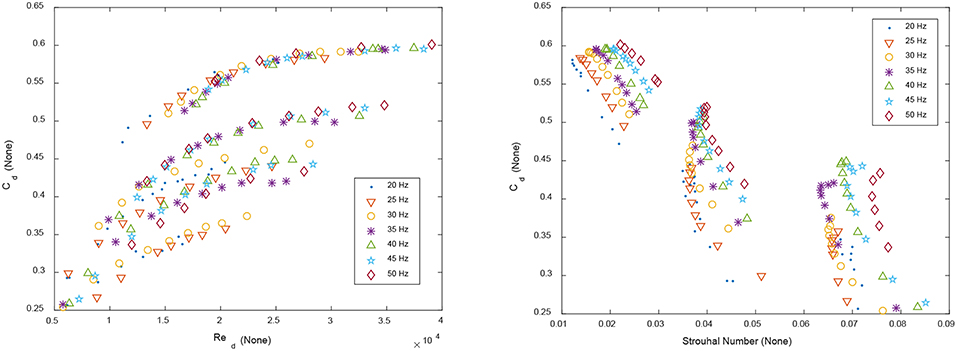
Figure 4. Left: Discharge Coefficient Cd calculated for the 189 data points generated by the pulsating flow apparatus as per the test plan shown by Table 1. Orifice β = 0.30. Right: Discharge Coefficient Cd plotted against the Strouhal Number defined for an orifice by Equation (5).
Dimensional analysis was performed to find dimensionless groupings to explain the large variation of Cd's. No single dimensionless parameter could reduce the variation to below the general uncertainty level of ±0.01 (uncertainty analysis is presented later), hence pairs of dimensionless groups were investigated. The following pair of variables produced the best results, Cd = Cd(η, ξ) where:
and
Here, σΔp is the standard deviation of the pulsating Δp (non-damped measurement), is the physically averaged pressure using the damped tube, ρ is the density at the orifice and is the average pipe velocity at the orifice. Both η and ξ are ξ are non-dimensional measures of pulsation, normalized by the upstream dynamic pressure and the average pressure drop across the orifice , respectively. These two latter variables (the two denominators) were almost perfectly correlated for steady flow at high Reynolds numbers (since from Equation 3), but not for pulsating flow; a plot is available in Figure A7 in Supplementary Material. Since both and are dominant terms of an integral momentum or energy balance across the orifice, and since they are not strongly correlated for pulsating flow, both are required to characterize pulsation.
As either η or ξ is increased, flow resistance increased, i.e., Cd decreased. This is shown by Figures 5A,B. The highest η and ξ were obtained at higher system pressures (larger pulsations achieved by closing V2) and low flow rates (lower velocity and pressure drop achieved by opening bleed valve V1). For similar velocity and pressure drop, higher system pressure resulted in larger pulsations.
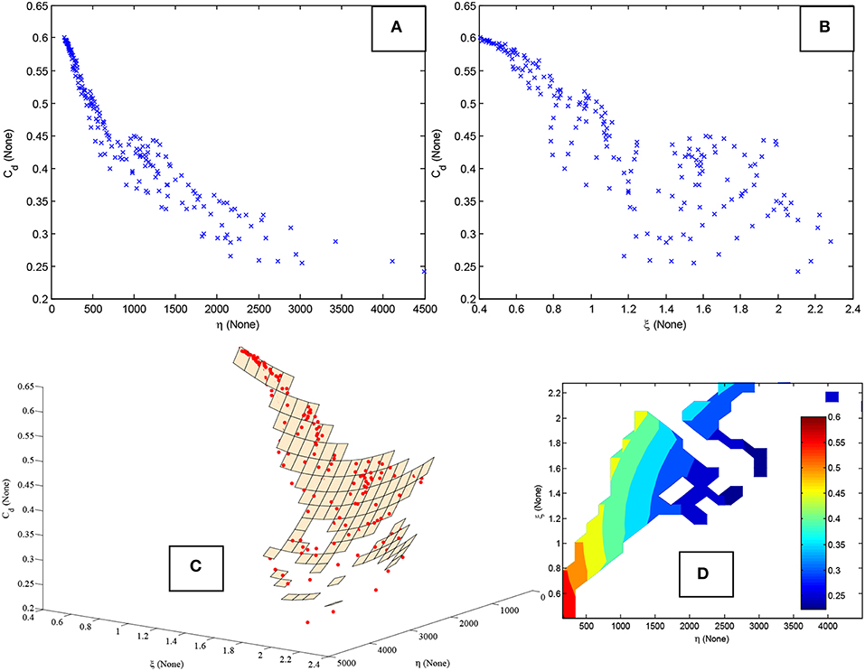
Figure 5. (A,B) Discharge Coefficient plotted against dimensionless variables η and ξ. The variation of Cd at any η is explained by ξ. (C) The Cd data shown by the red dots lie on a quadratic η − ξ surface generated by a linear regression model. (D) The contour plot further illustrates the non-linear response surface.
The variation in Cd at any given η could be explained by ξ. This is illustrated by Figure 5C which shows a quadratic surface generated by linear regression with all the data plotted on the response surface (left subplot). In general, all 189 points were located very close to the quadratic surface.
The corresponding contour plot is shown by Figure 5D. Only those parts of the surface in the vicinity of data points have been shown; the rest of the response surface is extrapolation and not shown. The data occupies only a fraction of the two-dimensional η -ξ space because both variables are correlated.
The accuracy of the η -ξ surface was assessed by 10-fold cross-validation. The widely used recommendations made by Weiss and Kulikowski (1991) for estimating the predictive capability of an empirical model built with between 100 and 1,000 data points, were followed. Nine-tenths of the randomized data was used to build the regression model which was then evaluated on the remaining one-tenth, and the process was repeated ten times, with different on-tenth splits chosen each time to cover all the data. Figure 6 shows predictions made with the regression model (Figure 6A) and k-nearest neighbor (kNN) algorithm (Figure 6B).
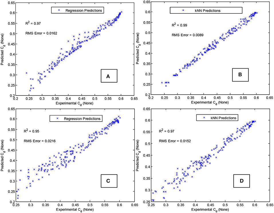
Figure 6. (A,B) Predictive accuracy of quadratic η -ξ surface using regression (A) and k-Nearest Neighbor algorithm (B). (C,D) Corresponding results without using average measured velocity (unknown for most practical applications). Regression results (C) and k-Nearest Neighbor algorithm results (D) using velocity calculated from isentropic relations.
The kNN algorithm simply chooses k training data points that are nearest to the test point to be predicted (k = 1 for this work). It is independent of the shape of the response surface; hence it was chosen to compare parameter pairs that would best predict Cd. The η -ξ pair performed better than all other possible pairs, as shown by Table 2. All parameters are listed in ascending order of RMS error resulting from the 10-fold cross-validation process.
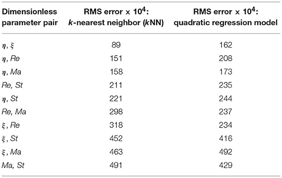
Table 2. Ten-fold cross-validation errors resulting from of all ten possible pairings using the five dimensionless parameters resulting from dimensional analysis: η, ξ, Reynolds number (Re), Mach number (Re), and Strouhal number (St).
More than two parameters did not produce any significant improvement in predicting Cd. For regression, the quadratic surface is only an approximation. It performed better than a linear or pure quadratic surface (no interaction terms) bit it is not known if the “true” surface is quadratic. The regression errors could possibly be further reduced by a different surface, e.g., exponential surface, but such an exploration is not feasible with this data for reasons described later.
Two interesting observations were made. If the numerical average of pulsating signal was used to calculate Cd (instead of the physical average), the predictions improved. Second, the pulsating signal used for calculating σΔp was acquired at 1,000 Hz, but the results did not suffer significantly until the data acquisition frequency was reduced to 2 Hz, much below the pulsating frequency of 20–50 Hz. This suggests that a data acquisition frequency allowing accurate standard deviation estimation is sufficient. Why σΔp is necessary, and whether it is sufficient to characterize complex pulsating patterns is not known.
The results presented so far are interesting starting points for fundamental investigations but not useful from a practical standpoint. This is because the determination of η requires knowledge of the average pipe velocity, which is unknown in most practical situations. In fact the usual purpose of using a discharge co-efficient is to determine the mass flow rate, which in turn is required to calculate velocity. An alternative is to use the velocity resulting from an isentropic expansion assumption:
The po ≈ p1 approximation is justified for this dataset because none of the 189 data points had more than a 0.025% difference between and (and the dynamic pressure term did not exceed 0.05% of p1 for any data point). Since the velocity calculated from Equation (8) corresponds to imaginary isentropic conditions, reasonable predictions could no longer be made with only ηisentropic and ξisentropic. It was found that both kNN and regression generated quadratic surface required the use of all dimensionless parameters i.e., Cd = Cd(ηisentropic, ξisentropic, Reisentropic, Maisentropic, Stisentropic), unlike the situation with measured average velocity. Corresponding 10-fold cross-validation results for regression and the kNN algorithm are shown in Figures 6C,D, respectively. Both algorithms used the logarithmic values of the five dimensionless parameters, to reduce correlation between variables and avoid rank deficient matrices. As expected, the results are worse than those shown by Figures 6A,B where the measured average velocity was used to calculate η. Still, a practical estimate of Cd within ±0.05 can be useful for a practical application if Cdranges between 0.25 and 0.60.
Engine Results
All the observations described above also held true for the engine data. Figure 7 shows the variation of Cdwith Reynolds number (left) and Strouhal number (right). The range of Reynolds number, about 40,000–160,000 is higher than the apparatus (5,000–40,000) due to the difference in the flow rates between the four cylinder engine and the single cylinder compressor. A wide range of Cd's ranging between 0.60 and 0.90 is observed. The higher values compared to the apparatus (0.25–0.60) might be due to the engine flows being in the critical or near-critical range. Similar numbers have been reported in the literature for steady (non-pulsating) critical flows (Grace and Lapple, 1951; Jackson, 1963; Kastner et al., 1964; Deckker and Chang, 1965; Rohde et al., 1969; Brain and Reid, 1975; Ward-Smith, 1979) in the 0.80–1.00 range. As mentioned before, no literature on pulsating critical flow could be found.
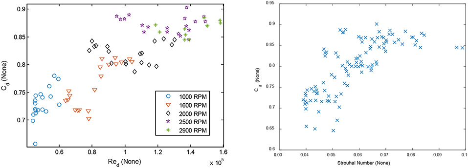
Figure 7. Left: Engine data showed a large variation in Cd and suggests that Red and Cdare unrelated (though correlated) or that other additional variables determine Cd. The lines are best fit lines at each RPM. The non-pulsating Cd was calculated by using a mathematical function from the (Fluid Meters, 1971b) ASME report (Brahma, 2011). Right: The variation of Cd is not explained by the Strouhal number either.
For steady flow, according to the equation/tables in 1971 ASME report (Fluid Meters, 1971b), the Cd for the same diameter ratio β = d/D = 0.26 was virtually constant at about 0.60 for the same Red range (40,000–160,000).
Although the discharge coefficient increased with Red, large variations in Cd at any given Red can be seen, suggesting they are unrelated (but correlated), or other additional variables determine Cd. Similar to the apparatus, Cd could not be satisfactorily correlated to any one dimensionless group, but was could be described by η and ξ. Out of the 105 engine data points, 62 were critical, based on peak pressure ratio across the orifice. For these data points, ξ was normalized using p1 rather than Δp as the denominator in Equation (7). show the surface and contour plots, respectively, for critical data points (non-critical points could not be plotted on this surface since ξ is defined differently). The surface and contours are qualitatively similar to the pulsating apparatus results shown by Figures 5C,D but more linear.
The accuracy of regression predictions is illustrated by Figures 8C,D. Both subplots show the results of 10-fold cross-validation, using measured average velocity (left) and using isentropic velocity (right), corresponding to the regression subplots of Figures 6A,C, respectively. Therefore, the left subplot shows results for a quadratic η -ξ surface, while the right subplot corresponds to a quadratic multivariate surface, i.e., Cd = Cd(ηpeak, ξpeak, Repeak, Mapeak, Stpeak) for predictions without knowledge of average velocity. Such a multivariate surface can be potentially useful for estimating EGR flow or modeling engine valves, where the average velocity is a-priori unknown. Predictive accuracy was within ±0.025; better than the pulsating data.
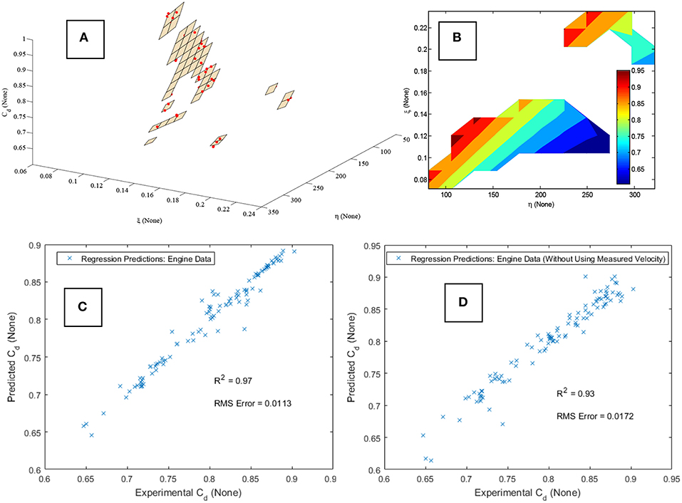
Figure 8. (A,B) The surface and contour plots for the engine data show a similar but less non-linear η -ξ surface than Figures 5C,D. (C,D) Engine data regression predictions using average velocity (C) and without using measured velocity (D), corresponding to the apparatus data regression predictions of Figures 6A and C respectively. Results for both the choked (N = 62) and non-choked (N = 43) data points have been combined.
Results from the 62 critical data points and 43 non-critical data points were combined for Figures 8C,D. Interestingly, the critical data when plotted by itself had significantly lower error (see Figure A8 in Supplementary Material). No clear criteria for classification of pulsating flow as critical or not could be found in literature. The peak pressure ratio of the pulsating signal was used to estimate Mach number at the orifice assuming isentropic expansion. This criterion and the implications of shifting it are discussed in a related work (Brahma, 2019) that has explored the possibility that pulsating flow might become critical earlier than steady flow due to acoustic effects.
Uncertainty Analysis
Repeatability and Random Error
Ten data points spanning the range of Cd values were chosen to determine repeatability of the data. These repeat points are overlaid over the 189 data points in Figure 9. The left subplot shows how the repeat points are uniformly distributed across the range of Cd's as well as the range of the primary dimensionless group η. Since Cd and η manly depended on the and σΔp measurement, respectively, the repeat points were chosen to be concentrated around the lower ranges of the -σΔp space, where the repeatability was expected to be worse. This is shown by the right subplot.
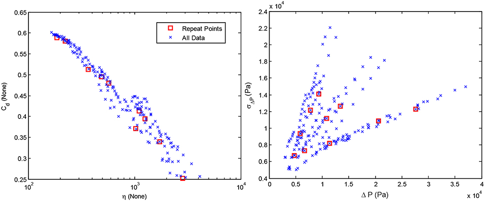
Figure 9. The repeat points chosen for uncertainty analysis overlaid over the 189 data points. They were chosen to span the range of Cd values, yet represent the lower range of the measurement, where uncertainty is higher. Note that the relationship between Cd and η appears linear on a logarithmic x-axis, as opposed to the non-linear relationship shown in Figure 5A.
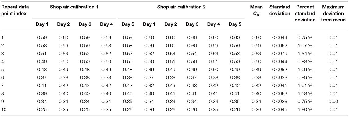
Acquisition of these ten data points was repeated on five different days spanning a month. The orifice temperature, pressure, differential pressure and Pitot-static measurement were maintained at identical values for each of the ten points. The five repeats were then processed using two separate Shop Air Calibrations (for calibrating Pitot-static area factor), performed on two different days. This resulted in ten different repeat datasets, shown by Table 3.
Note that changes in ambient temperature, barometric pressure and humidity over the month-long repeat data acquisition were accounted for. Overall, the data was highly repeatable with the average standard deviation of nearly 0.005 in the value of Cd. The maximum absolute deviation from mean for any of the 10 repeat points was about 0.01 while the highest percent standard deviation was 1.8% (for the smallest Cd).
The random uncertainty around the mean Cd for each of the ten repeat points, i.e., for each row of Table 3, was calculated at a 95% level using the t-distribution according to standard practice (Wheeler and Ganji, 2009):
Here, Sx is the sample standard deviation, M is the sample size (M = 10) and is the estimated standard deviation of the population.
Systematic Error and Total Uncertainty
Systematic error was calculated for each of the 10, repeat points using:
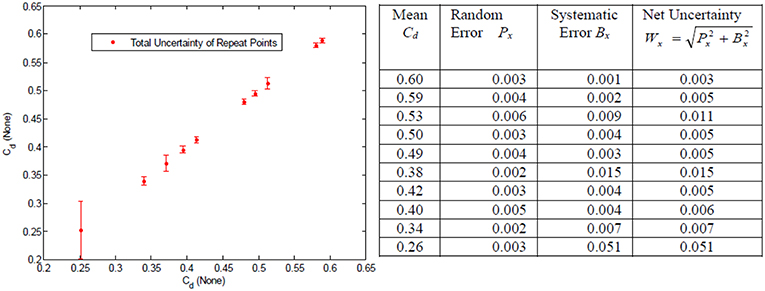
Here, wi's are the different measurements, i.e., orifice pressure, differential pressure, orifice temperature, pitot pressure/temperature, while the Ewi's are the systematic errors. The derivatives were computed numerically by the MATLAB code used to process the raw data to final Cd values, including code used for shop air calibration. Combined systematic errors were 0.5% of full scale for pressure measurements (Validyne Transducers) and 2.2°C for temperature measurements (Omega type “k” thermocouples). Since the ΔP term was overwhelmingly dominant, a more accurate determination of systematic errors for that measurement was undertaken. Non-linearity and hysteresis for each of the 10 ΔP measurements were determined using a NIST traceable reference pressure gage (plot available in Figure A9 in Supplementary Material). The error of the reference pressure gage (0.25% full scale) was also accounted for. Therefore, Equation (10) had three separate terms for the Δp measurement and four separate terms for each of the other four measurements. The total systematic error and the total uncertainty for all ten measurements are plotted and tabulated in Figure 10.
Based on this analysis it can be conservatively stated that total uncertainty is ±0.01 at any data point for which Cd > 0.30, otherwise it is ±0.05. The average over all ten repeat points was about 0.01. The root cause for the higher uncertainties at lower Cdis the low magnitude of . It can be seen from Figure 10 that low Cd's occur at higher η and ξ. The denominators of both these variables become smaller at low 's. In theory, this uncertainty could be reduced by a factor of 2 by using a transducer with lower full scale value, but this would require two transducers of different ranges for the data presented here.
Discussion
Overall, the RMS errors were generally comparable to the net uncertainty of about ±0.01 when measured average velocity was used to predict Cdin terms of η and ξ (Figures 6A,B, 8C), the only exception being regression predictions of Figure 6A.Without prior knowledge of the average velocity upstream of the orifice (using dimensionless variables based on isentropic velocity), RMS errors (Figures 6C,D, 8D) were about ±0.02. As noted previously that the η -ξ surface might not be quadratic at all. An empirical exploration of the “correct” functional dependence could not be undertaken because any mathematical function that approximates the ratio of the two variables, i.e., , will “fit” the data very well, since that ratio is the approximate definition of Cd. For example, although a linear relationship between Cd and log(η) was observed, any response surface with logarithmic variables produced near-perfect predictions, because the regression coefficients approximated the ratio . The quadratic model form was chosen because such confounding was not possible, but the “true” mathematical form, if it exists, is unknown. Similarly, the role of the dimensionless variables Ma, Re and St is unclear. Each of them, used in addition to η and ξ, resulted in only a small improvement, and did not appear vital. But all five variables produced a significant improvement when used together.
Based on the combined data generated from both systems, four inferences can be drawn with reasonable certainty:
a. Pulsating flow discharge coefficients are much more variable than non-pulsating cases. The current practice of using a constant Cd at high Red probably introduces significant error. This is evident from Figure 11 which shows data from both the pulsating apparatus and the engine on a single plot. For this combined data, Cd ranges from 0.20 to 0.90 as Red increases from 5,000 to 160,000.
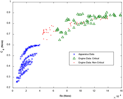
Figure 11. Combined data from engine and pulsating apparatus illustrate the greater range of Cd relative to non-pulsating flow.
b. The quasi-static assumption is not a good approximation: The quasi-static assumption predicts a Cd ranging between 0.60 and 0.62. No combination of quasi-static values can produce most of the pulsating Cd measurements shown in Figure 11. This suggests that the pulsating boundary layer and separation zone might be fundamentally different from steady flow phenomena. Hence a key assumption made by on-board EGR control strategies and system level engine simulation tools is not accurate and significant error is possible even if the pulsating wave dynamics is described accurately.
c. Pulsating critical/near critical Cd's are much higher than pulsating non-critical Cd's for about the same diameter ratio β, as evident from Figure 11, reasons unknown. A separate but related work examines the criteria for classifying pulsating flow as critical or not (Brahma, 2019), a question unanswered by literature because of the absence of work on pulsating critical flows.
d. The variables η and ξ are important variables for characterizing pulsating flow resistance. Figures 12A,B show Cd to be strongly correlated to both η and ξ for the combined dataset. As mentioned previously, the engine Cd's are higher (and slopes are different) possibly due to critical/near-critical flow. Engine η and ξ are smaller relative to the apparatus data because of higher flow rates, velocities and pressure drops. Since there was significant uncertainty in the measurement of the pulsating signal, the characterization is possibly better than shown.
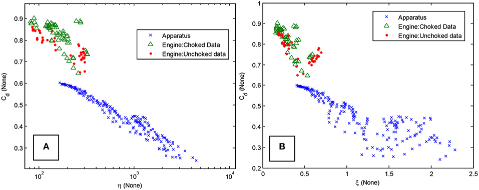
Figure 12. (A,B) Data from both systems plotted against η and ξ illustrates the strong correlations.
The original motivation of this work was to determine the root cause of inaccuracy in EGR flow and Volumetric Efficiency estimation during the turbocharger lag period, responsible for smoke spikes (Bean et al., 1929; Tuve and Sprenkle, 1933; Chilton and Handley, 1952). Based on this work it can be speculated that high pressure and low flow conditions encountered in the intake manifold and EGR system during the turbocharger lag period can possibly increase both η and ξ, thus increasing the flow resistance through engine valves, EGR valve and the air-handling plumbing, resulting in inaccurate ECM estimates of fuel-Oxygen ratio responsible for smoke spikes in electronically controlled engines.
Conclusions
The wide variation of discharge coefficients for a square-edged orifice in highly compressible pulsating flow was investigated and characterized by dimensionless groups. The work was motivated by inaccurate estimation of EGR flow and Volumetric Efficiency during the turbocharger lag period, based on constant discharge coefficient (Cd) assumption at high Reynolds numbers (Red). Results from an orifice placed in the exhaust stream of a four-cylinder diesel engine showed that Cd varied between 0.60 and 0.90 for Red ranging between 40,000 to 160,000 for critical/near-critical flows, typical of engines. Although correlated with Cd, Red did not explain the large variation in Cd. A pulsating flow apparatus was constructed to further investigate pulsating flow Cd under more controlled conditions with the ability to independently vary frequency, flow rate and system pressure with a wide range of consistent pulsating patterns. Based on experiments, physical rather than numerical filtering was performed to obtain a mean Δp signal, resulting in repeatable and reproducible Cd's independent of the transducer, transducer location and plumbing. Again a wide variation was observed, with Cd ranging between 0.25 and 0.60 for Redranging from about 5,000–40,000.
For the particular orifice tested, the quasi-static assumption predicts a Cd ranging between 0.60 and 0.62. Since the majority of pulsating Cd measurements were well outside that range, and given that the inertial effects were estimated to be small, the quasi-static assumption does not hold true for the data. This suggests that the pulsating boundary layer and separation zone might be fundamentally different from steady flow phenomena. A key assumption made by one-dimensional engine simulation tools might not be accurate. Accurate prediction of the wave dynamics through the engine system might not sufficient to determine the flow resistance of the system if quasi-steady assumptions are used.
The variation of Cd for both datasets was best explained by a pair of dimensionless variables η and ξ, defined as the standard deviation of the pulsating differential pressure signal across the orifice, normalized by the dynamic pressure and mean differential pressure, respectively. These variables were able to predict Cd with errors approaching experimental uncertainty, for both engine and pulsating apparatus data. The response surface for both datasets was qualitatively similar. For practical situations where the average velocity used to calculate η is unknown, reasonable predictions were made by using the isentropic velocity to normalize σΔp, although more than two dimensionless variables were required. There is room for improvement in the measurement of σΔp, by locating the transducer closer to the orifice and minimizing the volume of connecting tubing.
The flow resistance of cylinder valves, EGR valve, flow measurement orifices/flow-nozzles (if any) and engine plumbing might depend on variables similar to η and ξ. ECM estimates of EGR fraction and volumetric efficiency for emission control could benefit from a variable flow resistance assumption.
Fundamental studies involving the visualization and modeling of the pulsating boundary layer through an orifice are required to better understand the dimensionless variables η and ξ, their functional relationship with Cd, the role of St, Re and Ma, and the precise contribution of convective acceleration. The data from this work might be useful for this purpose.
Author Contributions
IB designed experiments, collected data and performed analysis.
Conflict of Interest Statement
The author declares that the research was conducted in the absence of any commercial or financial relationships that could be construed as a potential conflict of interest.
Acknowledgments
The author would like to thank Bucknell machinists Aaron Clark and Daniel Johnson for design and fabrication of the pulsating apparatus, undergraduate student Kevin VanDelden for apparatus design and initial data collection, and Bucknell laboratory director Hugh Weber for assembling the Variable Frequency Drive and assistance and guidance with fittings and measurement. The author is grateful to the mechanical engineering department at Bucknell University for providing the resources required for this work.
Supplementary Material
The Supplementary Material for this article can be found online at: https://www.frontiersin.org/articles/10.3389/fmech.2019.00025/full#supplementary-material
Abbreviations
ASME, American Society of Mechanical Engineers; Cd, Coefficient of Discharge; ECM, Electronic Control Module; EGR, Exhaust Gas Recirculation; ID, Inner diameter; kNN, k-Nearest Neighbor Algorithm; Ma, Mach number; OD, Outer diameter; Red, Reynolds number based on orifice diameter; RPM, Revolutions per minute (Engine Speed); St, Strouhal Number.
References
Ahn, K. H., and Ibrahim, M. B. (1992). Laminar/turbulent oscillating flow in circular pipes. Int. J. Heat Fluid Flow 13:340.
Baines, N. C., Hajilouy-Benisi, A., and Yeo, J. H. (1994). “The pulse flow performance and modelling of radial inflow turbines,” in Institution of Mechanical Engineers Conference Publications, Vol. 6 (London), 209-219.
Bean, H. S., Buckingham, E., and Murphy, P. S. (1929). Discharge coefficients of square-edged orifices for measuring the flow of air. J. Res. Nat. Bureau Standards 2:561.
Brahma, I. (2011). “An investigation into the causes of transient particulate matter spikes in production diesel engines,” in ASME 2011 Internal Combustion Engine Division Fall Technical Conference. Morgantown, WV: American Society of Mechanical Engineers, 765–783
Brahma, I. (2013). A decision-tree-based approach to smoke spike detection in a heavy-duty diesel engine. Proc. Inst. Mech. Eng. Part D J. Automob. Eng. 227, 1112–1129. doi: 10.1177/0954407012464314
Brahma, I. (2014). Analysis and prediction of transient opacity spikes using dimensional modeling. Int. J. Engine Res. 15, 263–281. doi: 10.1177/1468087413475807
Brahma, I. (2019). “Measurement and characterization of flow resistance of critical and near critical pulsating flow through an orifice located in the exhaust stream of a diesel engine,” in SAE Technical Paper. doi: 10.4271/2019-01-1176
Brahma, I., Schmidt, J., Confair, R., Kurtz, J., Rafter, I., and Stryker, P., et al. (2014). An investigation into the accuracy of orifice based flow estimates for pulsating compressible flows. SAE Int. J. Engines 7, 313–322. doi: 10.4271/2014-01-1154
Brain, T. J. S., and Reid, J. (1975). Performance of Small Diameter Cylindrical Critical Flow Nozzles. National Engineering Laboratory Report.
Capobianco, M., and Gambarotta, A. (1992). Variable geometry and waste-gated automotive turbochargers: measurements and comparison of turbine performance. J. Eng. Gas Turbines Power 114, 553–560.
Capobianco, M. G. A. C. G., Gambarotta, A., and Cipolla, G. (1989). “Influence of the pulsating flow operation on the turbine characteristics of a small internal combustion engine turbocharger,” in IMechE Paper (London), 063–069.
Çarpinlioglu, M. Ö., and Gündogdu, M. Y. (2001). A critical review on pulsatile pipe flow studies directing towards future research topics. Flow Measurement Instrumentation 12, 163–174. doi: 10.1016/S0955-5986(01)00020-6
Chilton, E. G., and Handley, E. R. (1952). Pulsations in gas compressor systems. Transac. ASME 74:931.
Copeland, C. D., Martinez-Botas, R., and Seiler, M. (2011). Comparison between steady and unsteady double-entry turbine performance using the quasi-steady assumption. J. Turbomachinery 133:031001. doi: 10.1115/1.4000580
Daily, J. W., Hankey, W. L., Olive, R. W., and Jordaan, J. M. (1955). Resistance Coefficients for Accelerated and Decelerated Flows Through Smooth Tubes and Orifices (No. 55-SA-78). Cambridge: Massachusetts Institute of Technology.
Dale, A., and Watson, N. (1986). “Vaneless radial turbocharger turbine performance,” in ImechE Conference Transactions, Tturbochargers and Turbocharging (London), 65–76.
Deckker, B. E. L., and Chang, Y. F. (1965). “Paper 7: an investigation of steady compressible flow through thick orifices,” in Proceedings of the Institution of Mechanical Engineers, Conference Proceedings, Vol. 180 (London: Sage Publications), 312-323.
Doblhoff-Dier, K., Kudlaty, K., Wiesinger, M., and Gröschl, M. (2011). Time resolved measurement of pulsating flow using orifices. Flow Measurement Instrumentation 22, 97–103.
Fluid Meters (1971a). American Society of Mechanical Engineers, 6th Ed. Chapter I–V, New York, NY: ASME
Fluid Meters (1971b). American Society of Mechanical Engineers, 6th Ed. Chapter II–III, New York, NY: ASME.
Fluid Meters (1971c). American Society of Mechanical Engineers, 6th Ed. Chapter II, New York, NY: ASME.
Gajan, P., Mottram, R. C., Hebrard, P., Andriamihafy, H., and Platet, B. (1992). The influence of pulsating flows on orifice plate flowmeters. Flow Measurement Instrumentation 3, 118–129.
González, N. F., Kindelán, J. C., and Mart,í, J. M. L. (2016). Methodology for instantaneous average exhaust gas mass flow rate measurement. Flow Measurement Instrumentation 49, 52–62. doi: 10.1016/j.flowmeasinst.2016.04.007
Grace, H., and Lapple, C. E. (1951). Discharge coefficients of small-diameter orifices and flow nozzles. Trans. ASME 73:639.
Gundogdu, M. Y., and Carpinlioglu, M. O. (1999a). Present state of art on pulsatile flow theory: part 1: laminar and transitional flow regimes. JSME Int. J. Ser. B Fluids Thermal Eng. 42, 384–397.
Gundogdu, M. Y., and Carpinlioglu, M. O. (1999b). Present state of art on pulsatile flow theory: part 2: turbulent flow regime. JSME Int. J. Ser. B Fluids Thermal Eng. 42, 398–410.
He, S., and Jackson, J. D. (2009). An experimental study of pulsating turbulent flow in a pipe. Eur. J. Mech. B Fluids 28, 309–320. doi: 10.1016/j.euromechflu.2008.05.004
Iguchi, M., and Ohmi, M. (1982). Transition to turbulence in a pulsatile pipe flow: part 2, characteristics of reversing flow accompanied by relaminarization. Bull. JSME 25, 1529–1536.
ISO (1998). Measurement of Fluid Flow in Closed Conduits-Guidelines on the Effects of Flow Pulsations on Flow Measurement Instruments.
Jackson, R. A. (1963). The compressible discharge of air through small thick plate orifices. Appl. Scient. Res. Sec. A 13, 241–248.
Kastner, L. J., Williams, T. J., and Sowden, R. A. (1964). Critical-flow nozzle meter and its application to the measurement of mass flow rate in steady and pulsating streams of gas. J. Mech. Eng. Sci. 6, 88–98.
Kosuge, H., Yamanaka, N., Ariga, I., and Watanabe, I. (1976). Performance of radial flow turbines under pulsating flow conditions. J. Eng. Power 98, 53–59.
Lichtarowicz, A., Duggins, R. K., and Markland, E. (1965). Discharge coefficients for incompressible non-cavitating flow through long orifices. J. Mech. Eng. Sci. 7, 210–219.
Liu, Z., and Copeland, C. (2018). New method for mapping radial turbines exposed to pulsating flows. Energy 162, 1205–1222. doi: 10.1016/j.energy.2018.08.107
Marelli, S., Capobianco, M., and Zamboni, G. (2014). Pulsating flow performance of a turbocharger compressor for automotive application. Int. J. Heat Fluid Flow 45, 158–165. doi: 10.1016/j.ijheatfluidflow.2013.11.001
Nakamura, H., Asano, I., Adachi, M., and Senda, J. (2005). Analysis of pulsating flow measurement of engine exhaust by a Pitot tube flowmeter. Int. J. Engine Res. 6, 85–93. doi: 10.1243/146808705x7329
Ohmi, M., Iguchi, M., and Urahata, I. (1982). Transition to turbulence in a pulsatile pipe flow part 1, wave forms and distribution of pulsatile velocities near transition region. Bull. JSME 25, 182–189.
Reis, M. N., and Hanriot, S. (2017). Incompressible pulsating flow for low Reynolds numbers in orifice plates. Flow Measurement Instrumentation 54, 146–157. doi: 10.1016/j.flowmeasinst.2017.01.001
Rohde, J. E., Richards, H. T., and Metger, G. W. (1969). Discharge Coefficients for Thick Plate Orifices with Approach Flow Perpendicular and Inclined to the Orifice Axis. National Aeronautics and Space Administration, NASA TN D-5467.
Sparks (1966). “A study of pulsation effects on orifice metering of compressible flow,” in Flow Measurement Symposium, 231.
Tuve, G. L., and Sprenkle, R. E. (1933). Orifice discharge coefficients for viscous liquids. Instruments, 6, 201–206.
Ward-Smith, A. J. (1979). Critical flowmetering: the characteristics of cylindrical nozzles with sharp upstream edges. Int. J. Heat Fluid Flow 1, 123–132.
Weiss, S. M., and Kulikowski, C. A. (1991). Computer Systems That Learn: Classification and Prediction Methods from Statistics, Neural Nets, Machine Learning, and Expert Systems. San Francisco, CA: Morgan Kaufmann Publishers Inc.
Wheeler, A. J., and Ganji, A. R. (2009). Introduction to Engineering Experimentation, 3rd Ed. Pearson.
Keywords: compressible flow, pulsating flow, unsteady flow, choked flow, EGR flow, orifice discharge coefficient, flow measurement, flow resistance
Citation: Brahma I (2019) Measurement and Prediction of Discharge Coefficients in Highly Compressible Pulsating Flows to Improve EGR Flow Estimation and Modeling of Engine Flows. Front. Mech. Eng. 5:25. doi: 10.3389/fmech.2019.00025
Received: 13 October 2018; Accepted: 17 April 2019;
Published: 13 May 2019.
Edited by:
Evangelos G. Giakoumis, National Technical University of Athens, GreeceReviewed by:
Ming Zhai, Harbin Institute of Technology, ChinaAgostino Gambarotta, University of Parma, Italy
Copyright © 2019 Brahma. This is an open-access article distributed under the terms of the Creative Commons Attribution License (CC BY). The use, distribution or reproduction in other forums is permitted, provided the original author(s) and the copyright owner(s) are credited and that the original publication in this journal is cited, in accordance with accepted academic practice. No use, distribution or reproduction is permitted which does not comply with these terms.
*Correspondence: Indranil Brahma, aWIwMTFAYnVja25lbGwuZWR1
 Indranil Brahma
