 Ming-Ming Ji
 Wei Chen1
 Yan Xiong
 Xin-Yu Zhao
94% of researchers rate our articles as excellent or good
Learn more about the work of our research integrity team to safeguard the quality of each article we publish.
Find out more
ORIGINAL RESEARCH article
Front. Mater. , 08 January 2025
Sec. Structural Materials
Volume 11 - 2024 | https://doi.org/10.3389/fmats.2024.1525718
This article is part of the Research Topic Static and Dynamic Performance Analysis of Structures and Materials Under Complex Loads and Environmental Excitation View all 10 articles
Precast systems are increasingly favored in modern construction to meet the growing demands for faster project delivery, cost control, and enhanced quality assurance. Yet, the feasibility of connections between precast elements remains a crucial factor affecting the overall structural performance of these systems. Considering the versatility and dimensional consistency of structural steel sections, this study introduces an emulative column-to-column hybrid connection achieved by using welding-spliced steel tubes, with a view to improving assembly efficiency and on-site quality control. Reversed cyclic loading tests were conducted on five near full-scale column specimens to assess the seismic performance of the proposed connection. Results indicated that this connection method could provide seismic performance comparable to that of the traditional cast-in-place counterpart. Nevertheless, the anchorage of the column longitudinal rebars played a critical role, as inadequate anchorages led to significant reductions in the columns’ lateral capacity. For this reason, increasing the tube thickness was shown to be insufficient as a substitute for proper anchorage detailing. Moreover, it was found that the incorporation of the welded steel tubes shifted the plastic hinge region upward, resulting in a more extended damage zone—a consequence of the localized stiffening effect. Finally, existing equations and methods are employed to evaluate the lateral strength, load-displacement response, and plastic hinge length of the tested specimens.
Precast concrete systems have become an integral part of modern construction, offering distinct advantages such as reduced labor demands, enhanced quality control, and improved environmental sustainability compared to traditional cast-in-place (CIP) methods (Englekirk, 2003; Hong et al., 2018; Wong and Loo, 2022). Off-site manufacturing enables higher precision and better material efficiency, while also minimizing waste and environmental impact (Yee, 2001a; Yee, 2001b; Zhang X. et al., 2024). These benefits make precast systems ideal for applications ranging from buildings and industrial complexes to large-scale infrastructure projects. However, ensuring the reliability of connections between precast components remains a big challenge—especially in seismic regions, where these connections must accommodate large lateral deformations without compromising structural integrity (ACI 550R-96, 2001; Khaloo and Parastesh, 2003; Elliott and Jolly, 2013; Kurama et al., 2018; Ghayeb et al., 2020a; Hu et al., 2024; Zhang R. et al., 2024).
Currently, grouted sleeve connectors have been typically used in precast connections (Einea et al., 1995; Ameli et al., 2016; Tullini and Minghini, 2016; Fan et al., 2020; Liu et al., 2021; Xu et al., 2022; Zhang et al., 2023). While effective in load transfer and offering construction tolerances, they present notable drawbacks. For instance, the grouting process can be labor-intensive and time-consuming, with outcomes heavily influenced by site conditions (Yao et al., 2021; Li et al., 2021). Moreover, these connectors are concealed within concrete, making post-installation inspection and maintenance challenging (Henin and Morcous, 2015; Durgarian et al., 2022).
More critically, grouted sleeve connectors exhibit inherent seismic limitations, particularly in displacement ductility. Studies have reported reductions of up to 50% in ductility for precast columns with grouted sleeves compared to their monolithic counterparts (Haber et al., 2014; Tazarv, 2014; Ameli et al., 2015; 2016; Al-Jelawy et al., 2018). Liu et al. (2021) noted that while these connectors performed adequately under moderate axial loads, their energy dissipation and ductility significantly declined at higher axial loads. These findings emphasize the need for more robust and resilient connection systems capable of delivering reliable structural performance under seismic conditions.
To address these challenges, alternative connection methods have been widely investigated. A range of innovative solutions has been proposed to simplify construction processes, improve structural performance, and facilitate maintenance (as summarized in, e.g., Englekirk, 2003; Dal Lago et al., 2018; Ghayeb et al., 2020b; Guaygua et al., 2023). These strategies often involve mechanical connections using bolts, splices, or similar devices (Vidjeapriya and Jaya, 2013; Yekrangnia et al., 2016; Han et al., 2018; Baran et al., 2021; Nascimbene and Bianco, 2021; Qing et al., 2022; Zhou et al., 2022; Ahn et al., 2023), as well as prestressed or post-tensioning tendons, strands, rods, or reinforcing bars (Stone et al., 1995; Wang et al., 2018; Quiel et al., 2019; Kim et al., 2021; Kim et al., 2022). Welded connections have also been explored (Bhatt and Kirk, 1985; Ersoy and Tankut, 1993; Naito et al., 2012; Rodríguez and Torres-Matos, 2013; Girgin et al., 2017; Menegon et al., 2020; Dal Lago et al., 2022). Furthermore, the incorporation of high-performance materials has demonstrated potential for improving structural performance and ductility in precast connections (Xu et al., 2019; Ma et al., 2021; Zhang X. et al., 2024).
Among the emerging innovations, hybrid precast beam-to-column connections have shown significant promise. Ghayeb et al. (2023) conducted a comprehensive review of these systems, categorizing them into three types: Type I (dry and wet connections utilizing steel sections), Type II (composite material-based systems), and Type III (a combination of Type I and Type II). Their findings highlight the robustness and adaptability of steel sections integrated with the inherent advantages of precast concrete, effectively replicating the behavior of monolithic connections.
As early as the 1980s, Pillai and Kirk (1981) used steel plates to connect precast beam bars with reinforcing bars in the core of the joint through welding. They observed that all precast specimens endured an equal or greater number of lateral load cycles compared to their cast-in-place counterparts, achieving nearly twice the ultimate rotation. Since then, numerous studies have made use of the flexibility, dimensional precision, and availability of steel sections for precast joint detailing. For example, Korkmaz and Tankut (2005) explored a precast beam-to-beam connection using welded plates at the bottom and lap splices for the top steel, which exhibited satisfactory performance under testing. Later on, Li et al. (2009) employed steel angle sections to connect precast beams and columns, demonstrating adequate ductility and strength under cyclic loading, comparable to monolithic specimens. Their results also revealed that embedding steel sections in joint core greatly enhanced its strength, enabling specimens to carry story shears up to a drift ratio of 3.5. Choi et al. (2013) developed a wet precast connection with steel plates for joint continuity, achieving improved strength and ductility under cyclic loading. In a related effort, Ghayeb et al. (2017) introduced a dry precast connection combining steel plates and bolts, which delivered a superior seismic response compared to conventional CIP specimens, along with more stable load-displacement behavior and greater energy dissipation. Notably, the dry connection achieved drift ratios as high as 9.0%.
In recent years, research on hybrid precast connections has expanded significantly, offering valuable insights into the development of precast structures. Ghayeb et al. (2020a) proposed hybrid connections incorporating steel tubes, plates, and couplers, which demonstrated attainable drift ratios up to 50% higher than monolithic connections. Senturk et al. (2020) developed a monolithic-like precast connection with bolted plates, achieving a 34% improvement in both ductility and ultimate deformability. Zhang et al. (2020) advanced the field further by designing a precast connection system integrating highly ductile rods or steel shapes within the joint core. This approach significantly enhanced strength, reduced stiffness degradation, and improved energy dissipation, outperforming conventional monolithic designs. In addition, the addition of steel fiber concrete further boosted seismic performance. Ye et al. (2021) proposed a hybrid beam-to-column connection using an I-steel connector with high-strength bolts, which effectively mitigated stress concentrations while matching the performance of CIP connections. Albright et al. (2022) proposed the “New Performance System” (NPS®), a steel-concrete composite moment-resisting frame with superior strength, stiffness, ductility, and energy dissipation under simulated seismic conditions. More recently, Guan et al. (2023) developed a partially precast steel-reinforced concrete (PPSRC) beam-to-column connection, which shifted the plastic hinge away from the joint, resulting in enhanced strength, ductility, and energy dissipation compared to traditional connections.
Despite these advancements, challenges remain in optimizing these hybrid connections for practical application. Complex construction processes, high costs, and the need for specialized materials or workmanship continue to hinder wider adoption. Therefore, innovative solutions are still needed to balance structural performance with practical feasibility.
In response to these challenges, this study proposes a beam-to-column hybrid connection, as illustrated in Figure 1. This connection is achieved through welding-spliced steel tubes. The longitudinal rebars of the upper and lower precast columns are welded to the steel tubes embedded in the respective columns. The upper column includes a shorter steel tube connector, while the lower column features a longer steel tube extending through the joint core. The bottom longitudinal rebars of the precast beams are bent and anchored to a steel corbel extending from the lower column’s steel tube (for clarity, this detail is omitted in Figure 1). The upper longitudinal rebars of the precast beams pass through pre-formed holes in the steel tube during construction. On-site, the steel tube connector of the upper column is welded to the steel tube of the lower column (Figure 1). Finally, the lower steel tube is filled with concrete through an inclined closure pour hole in the upper column, forming the proposed hybrid connection.
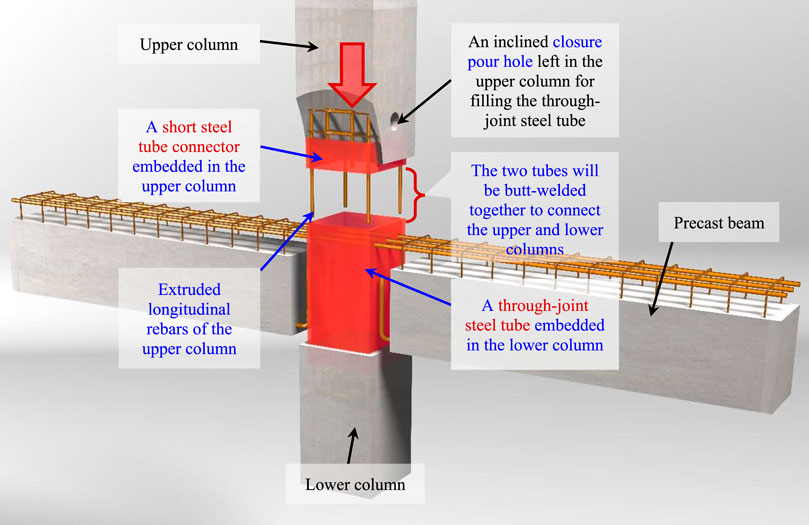
Figure 1. A emulative connection using butt-welded steel tubes embedded in precast columns.
Compared to traditional grouted sleeve connections, this new connection eliminates the need for on-site grouting of the main reinforcement, thereby mitigating potential quality issues associated with grouting inconsistencies. Additionally, the welding-spliced steel tubes leverage the adaptability and dimensional precision of structural steel sections, which simplifies installation and improve alignment during assembly. Welding, a familiar practice for construction workers, enhances reliability compared to the complexities of sleeve grouting.
As noted by Alfred A. Yee over 60 years ago (Yee, 1962), maintaining dimensional accuracy in precast concrete production remains a significant challenge due to concrete’s heterogeneity and the variability of materials and processes involved. Factors such as aggregate type, cement content, and curing methods contribute to dimensional discrepancies, including length, camber, or twist. Human errors, such as misplacement of inserts or mismeasurement, exacerbate these issues, leading to costly errors in both field and factory. By incorporating the precision of structural steel sections, installation efficiency in precast systems can be greatly improved. This is the underlying rationale behind the development of the proposed hybrid connection.
Apparently, the column-to-column connection is a pivotal part of the proposed hybrid connection. To evaluate its efficiency and robustness, five large-scale specimens were tested to failure under lateral load reversals. The key experimental parameters included the anchorage conditions of column longitudinal rebars within the joint’s steel tube (i.e., the steel tube extended from the lower column), as well as the thickness of the spliced steel tubes, both of which would significantly affect the connection’s performance. The experiments assessed critical seismic behaviors, including hysteresis response, energy dissipation, and strength degradation. Additionally, this study explored how to predict the lateral strength, load-displacement response, and plastic hinge length of the column specimens. The outcomes of this study will serve as a basis for future research on the beam-to-column connection concerned.
The experimental program for this project included a total of five square column specimens: four precast columns (designated as PC-C1 to PC-C4) and one reference cast-in-place column (CIP-C0). The assembly process for the precast specimens is illustrated in Figure 2, while Figure 3 provides the structural details of all specimens. Key experimental parameters are summarized in Table 1. Each specimen was nearly full-scale, with a total height of 2,200 mm (including the foundation beam). The effective column shaft length (measured from the load point center to the foundation beam top) was thus 1,400 mm. The column shafts had a square cross-section measuring 400 mm × 400 mm.

Figure 2. Schematic of assembly of the precast column model.
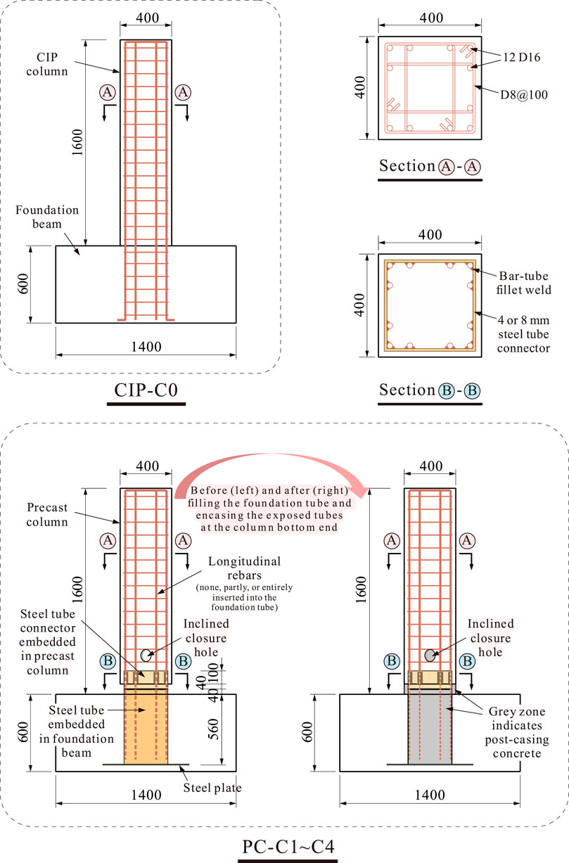
Figure 3. Design details of column specimens (unit: mm).
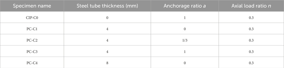
Table 1. Test matrix of specimens.
The specimens were designed to investigate the influence of two primary parameters on the performance of the proposed connection:
(1) Anchorage ratio of column longitudinal rebars: This parameter was varied to examine how the degree of rebar engagement within the steel tube embedded in the foundation beam (referred to as the base steel tube or the foundation steel tube) affects the lateral load transfer mechanism and overall seismic performance. Specifically, these anchorage ratios were 0 (no rebar extended), 1/3 (only the four corner rebars extended), 1 (all rebars fully extended), and 0 for PC-C1, PC-C2, PC-C3 and PC-C4, respectively. These ratios chosen (0, 1/3, 1) represent typical configurations in practical precast design scenarios;
(2) Steel tube thickness: Two thickness levels (4 mm and 8 mm) were selected to study the effect of localized stiffening on the plastic hinge behavior and the distribution of damage. Specifically, the steel tube wall thickness was 4 mm for PC-C1 through PC-C3, while PC-C4 had a thicker tube of 8 mm. All the steel tubes had a uniform side length of 340 mm. From Figure 3, it can be observed that after the steel tube connector in the precast column was aligned and welded to the extruded steel tube in the foundation beam, the exposed length of the steel tubes outside the concrete was 80 mm.
The above test parameters were chosen because they are critical to the performance of the proposed connection. The anchorage ratio directly influences the interaction between the longitudinal rebars and the steel tubes, while the steel tube thickness governs the tube’s ability to resist local buckling and contribute to force transfer.
All specimens were subjected to a constant axial compression ratio of 0.3. The fabrication process for the precast specimens is detailed in Figure 4. Fabrication began with tying reinforcement for the column shaft and foundation beam. Each precast column had a 140-mm-tall steel tube connector embedded at its bottom end, with 40 mm extending beyond the concrete (Figure 4C). Inside the precast column, the longitudinal rebars were placed snugly against the inner surface of the tube connector. At the same time, the rebars and the connector were attached using 90-mm-long double-sided fillet welds (Figure 4A).
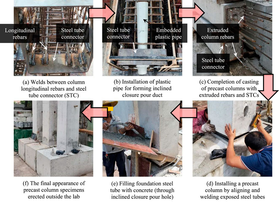
Figure 4. Casting and assembly process of specimens. (A) Welds between column longitudinal rebars and steel tube connector (STC) (B) Installation of plastic pipe for forming inclined closure pour duct (C) Completion of casting of precast columns with extruded rebars and STCs (D) Installing a precast column by aligning and welding exposed steel tubes (E) Filling foundation steel tube with concrete (through inclined closure pour hole) (F) The final appearance of precast column specimens erected outside the lab.
For the CIP-C0 specimen, a single continuous pour was employed. In contrast, the precast specimens were fabricated in two steps. First, the column shaft was cast and allowed to cure until the target strength was achieved. Next, the shaft was welded to the foundation’s base steel tube via full penetration butt welds at their beveled ends. Concrete was then poured through a 70-mm-diameter inclined closure hole and thoroughly vibrated to ensure proper consolidation. Finally, a thin layer of concrete was applied around the welded steel tubes to protect them and provide a smooth surface for the precast column shaft (Figure 4F).
The column shafts and the foundation beams were cast using C30-grade concrete (30 MPa design strength). During testing, the measured compressive strength of the concrete was 37.5 MPa (150-mm cube samples), while the post-cast concrete poured through the closure hole had a strength of 32.6 MPa. The reported strengths were averages based on at least three samples.
Both the steel tube connectors and foundation steel tubes were made of Q355-grade steel. For all of reinforcing bars used, the strength grade was HRB400. The columns were reinforced with twelve 16-mm-diameter longitudinal rebars, providing a reinforcement ratio of 1.51%. Stirrups were 8-mm-diameter four-legged ties, spaced at 100 mm. The actual tensile properties of the rebars and steel tubes were measured, with details provided in Table 2.

Table 2. Measured tensile strengths of steels used in the tests.
The experiments were conducted at the Structural Engineering Laboratory of South China University of Technology. Each specimens was anchored to the lab’s strong floor using a restraint system. Lateral loads were applied incrementally using an MTS electro-hydraulic actuator in a low-cycle push-pull manner. Additionally, a jack with roller supports was used to apply axial load to each specimen. The axial load was managed to keep constant at 1,400 kN, corresponding to an axial compression ratio of 0.3. The complete loading setup is shown in Figure 5.
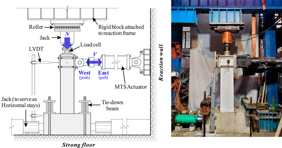
Figure 5. Test setup.
An array of linear variable displacement transducers (LVDTs) was mounted on the lower part of the specimens to monitor curvature changes and slip rotations there (Figure 6). Strain gauges were attached to key locations on the rebars and steel tubes within the columns and foundations. All instrument readings were automatically collected by a computer system. To better observe concrete cracking, each specimen was coated with whitewash.
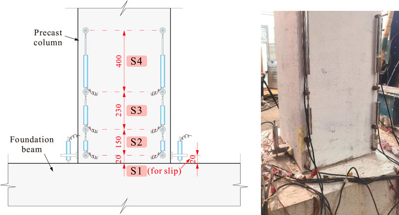
Figure 6. Arrangement of LVDTs within and beyond the column hinge zone (unit: mm).
According to ACI 374.1-05, (2005) guidelines, the cyclic loading was run in a displacement-controlled mode, with drift ratios stepping up as follows (±%): 0.1, 0.25, 0.50, 0.75, 1.0, 1.5, 2.0, 2.5, 3.0, 3.5, and 4.0. Each drift level was cycled three times. For safety, testing was terminated when the lateral load dropped to 80–85% of its peak value.
All the specimens demonstrated stable loading behavior until significant damage occurred. The cracking pattern and failure modes of both the monolithic and precast columns are shown in Figure 7. Flexural-dominated failure modes were observed across all specimens, characterized by concrete spalling and crushing concentrated in the lower regions of the columns. However, variations in the connection details resulted in differing extents and distributions of damage.
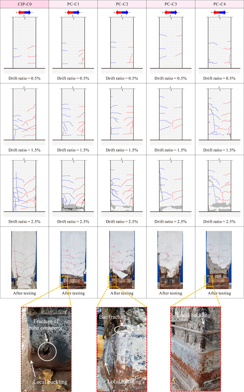
Figure 7. Failure process and final appearance of specimens.
During the initial loading phase, small horizontal hairline cracks were observed in all specimens. As the drift ratio increased, flexural cracks became more pronounced, and the concrete cover began to spall off, leading to flexural-compression failure near the column base. This failure was marked by crushed concrete and local buckling of the longitudinal rebars.
Most notably, in comparison to the CIP column, the precast columns displayed a broader failure zone due to the presence of welding-spliced steel tubes extending 180 mm from the column-foundation interface. This shifted the failure region upwards, where significant concrete spalling and longitudinal rebar buckling, including fractures, were observed (Figure 7). When the drift ratio reached 2.5%, several diagonal cracks appeared in specimens PC-C3 and PC-C4. Additionally, as the rebar anchorage ratio and steel tube thickness increased, the severity of the localized damage above the welded tubes intensified.
Specimen PC-C1, which lacked anchored rebars, relied primarily on the welded steel tubes to transfer internal forces (axial load, shear force, and bending moment) to the foundation beam. Under reversed cyclic loading, the corners of the steel tubes exhibited noticeable buckling, eventually tearing open during the later loading stages (Figure 7). This localized failure indicated that, in the absence of anchored column rebars and with thinner steel tubes, the welded tube region bore the majority of stresses, concentrating damage in themselves.
Specimen PC-C2, with a 1/3 rebar anchorage ratio (corner rebars only), displayed less severe buckling at the steel tube corners. Instead, localized buckling occurred at the central region of the welded tubes (Figure 7), and the longitudinal rebars above the tubes showed clear signs of local buckling. This suggested that the corner rebars extending into the foundation worked synergistically with the steel tubes to distribute internal forces, reducing the extent of tube damage. As a result, the failure zone shifted higher up compared to PC-C1.
Similarly, specimen PC-C3, featuring fully anchored longitudinal rebars, exhibited no apparent damage to the welded tubes (Figure 7). Instead, failure was concentrated in the column shaft above the tube region. Among all specimens, the upward shift in the failure zone was most pronounced in PC-C3. The increased flexural capacity in the welded tube region, resulting from the combined action of the steel tubes and fully anchored rebars, contributed to this phenomenon. This observation aligns with established findings in seismic studies, where localized strengthening alters failure progression and extends damage zones upwards (e.g., Al-Jelawy et al., 2018; Lee et al., 2022).
Specimen PC-C4, incorporating thicker welded steel tubes (8 mm) but no anchored rebars, exhibited an upward shift in the damaged zone similar to PC-C3. However, the absence of extended rebars limited the efficiency of load transfer. As a consequence, the increased tube thickness enhanced the flexural stiffness in the tube region but failed to improve overall lateral strength without proper rebar anchorage.
The broader damage zone observed in precast columns has both advantages and disadvantages: while it helps to distribute plastic deformations along the column shaft, potentially enhancing energy dissipation capacity (as detailed later), it also complicates post-earthquake repair due to the widespread nature of the damage.
It was also observed that the corner rebars in all precast columns (except PC-C1) fractured above the welded tubes. Still, none of the specimens exhibited any failure at the butt welds between the tube connector and the foundation tube. This confirmed the reliability of the welded connections, which showed no signs of detachment or weakness during testing.
The lateral load-displacement responses for each specimen, measured at the column tip, are illustrated in Figure 8, including both hysteresis loops (Figures 8A–E) and backbone curves (Figure 8F). As expected for concrete columns undergoing flexural-dominated failure, the hysteresis loops showed a typical “spindle” shape, indicative of full and stable energy dissipation.
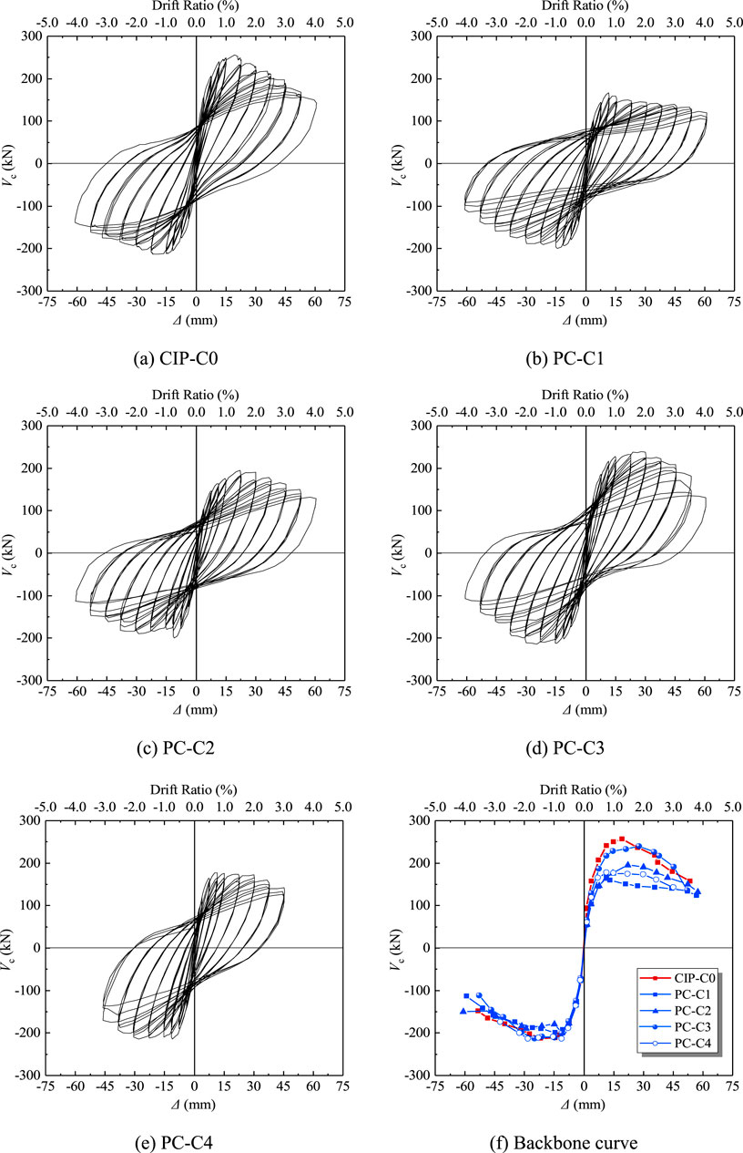
Figure 8. Lateral load-displacement responses of specimens. (A) CIP-C0 (B) PC-C1 (C) PC-C2 (D) PC-C3 (E) PC-C4 (F) Backbone curve.
Among the precast specimens, PC-C1 exhibited a significant reduction in lateral load-bearing capacity (around 20% on average) compared to the monolithic specimen (CIP-C0). PC-C2, with partially anchored longitudinal rebars, exhibited some recovery in lateral capacity compared to PC-C1, though it remained approximately 15% lower than CIP-C0. PC-C3, with fully anchored longitudinal rebars, demonstrated a load-bearing capacity nearly equivalent to CIP-C0, suggesting that the lateral resistance had been almost completely restored, although its peak load was reached slightly later. PC-C4, incorporating thicker steel tubes but no anchored rebars, showed only marginally higher lateral strength than PC-C1.
These findings clearly indicate that when the column longitudinal rebars are not anchored into the joint core (namely, the foundation beam in this testing setup), the load transfer mechanism depends on the welding-spliced steel tubes. Consequently, the lateral load-bearing capacity of the precast columns is reduced compared to the fully cast-in-place specimen. Three primary reasons may explain this reduction:
(1) Steel tube wall thickness: Although the overall cross-sectional area of the welded steel tubes was roughly equivalent to that of the column longitudinal rebars, the steel tube walls in PC-C1 to PC-C3, at only 4 mm thick, were susceptible to local buckling under flexural-compression loads. This buckling caused a measurable reduction in the peak load of the precast columns;
(2) Cold joint near the column-foundation interface: The presence of a cold joint between the precast column and the foundation beam hindered effective shear and moment transfer. Cold joints inherently create weak points where material continuity and structural integrity are compromised, especially under cyclic or seismic loading. This phenomenon is a known limitation of precast systems and one of the primary reasons why precast connections typically exhibit inferior performance compared to CIP connections (Englekirk, 2003; Kishen and Rao, 2007; Davaadorj et al., 2020);
(3) Post-Cast concrete strength: The compressive strength of the post-cast concrete used in the tests was lower than that of the precast concrete. This disparity further reduced the lateral load-bearing capacity of the precast columns.
Figure 9 attempts to explain the different failure mechanisms caused by whether or not the downward extension of the column longitudinal rebars was adopted. This figure, in combination with the test results for the columns’ lateral strength, highlights a clear relationship between the rebar anchorage and the load-resisting mechanisms. It is reasonable to believe that the presence of the cold joint could compromise the reliability of force transfer, particularly due to potential inconsistencies during the casting process. In such cases, the downward extension of the column rebars becomes especially critical. As the rebar anchorage ratio increased, the engagement of the longitudinal rebars improved, thereby reducing the reliance on the steel tubes to bear the entire load. This enhancement in load transfer paths allowed the lateral capacity of the precast columns to progressively recover, eventually matching that of the fully monolithic column.
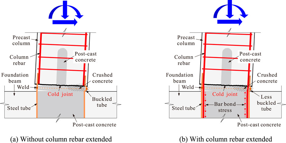
Figure 9. Failure mechanisms of precast column specimens. (A) Without column rebar extended (B) With column rebar extended.
It was observed that PC-C1 did not exhibit the gradual hardening trend seen in the other specimens during push-direction excursion. This lack of hardening resulted in an asymmetrical hysteretic response for PC-C1 between the push and pull directions. The exact cause of this behavior is not yet fully understood, but it is hypothesized that it may primarily be attributed to the absence of downward-extended longitudinal rebars into the base tube in PC-C1. Without these rebars, the force transfer mechanism heavily relies on the welded steel tubes, which could lead to less stable post-peak performance. Additionally, the presence of the cold joint might contribute to this phenomenon. In particular, there may have been “loose” contact between the post-cast concrete and the precast portion on one side of the column, affecting the load-resisting behavior. While this issue could potentially be mitigated by ensuring that the column rebars are extended into the base tube, as seen in other specimens, additional experimental evidence is required to verify whether this behavior is a general characteristic of this type of connection or a specimen-specific anomaly.
Another important observation from the design and testing phases was that merely increasing the steel tube thickness (i.e., reducing the width-to-thickness ratio) was insufficient to improve force transfer or lateral strength (as is the case of CIP-C4). This outcome underscores the inefficiency of increasing steel tube thickness alone, which not only results in excessive steel usage but also fails to address the underlying load transfer inefficiencies.
For optimal performance in engineering design, it is more effective to ensure that the steel tube’s yield capacity under lateral loads is well-matched to that of the longitudinal rebars. Furthermore, it is critical to anchor a portion of the longitudinal rebars inside the steel tube within the joint region. This anchorage is essential for the proposed precast connection system to achieve reliable performance. Beyond this, further increases in steel tube thickness appear to be unnecessary and unwarranted.
The primary test results for all specimens, including the ductility coefficient, are summarized in Table 3. According to Park et al. (1982), the displacement ductility coefficient, μ, is defined as μ = Δu/Δy, where Δu and Δy represent the ultimate and yield displacements, respectively.
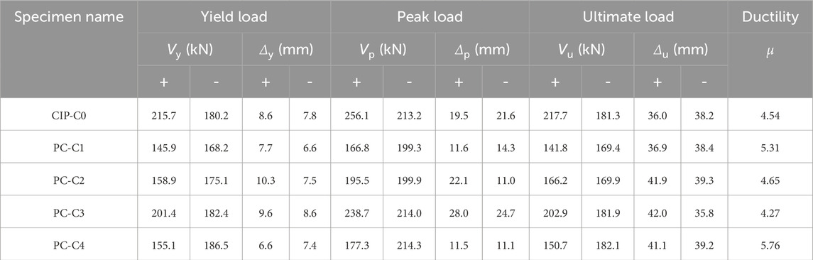
Table 3. Main test results.
From the results shown in the table, it is evident that the ductility coefficients of the precast column specimens are generally comparable to, or slightly higher than, those of the reference CIP specimen. This can likely be attributed to the different detailing solutions adopted by the CIP column and precast columns.
In the case of the CIP column, after reaching the peak load, the rebars at the column base began to buckle severely, engaging the stirrups and displacing them outward. As a result, the loss of confinement caused the concrete crushing zone to extend deep into the center of the column base (Figure 7). This uncontrolled breakdown of the concrete at the column base led to a sharper decline in the lateral strength.
In contrast, for the precast columns, although the steel tubes did not contribute to a higher lateral capacity, they continued to provide confinement to the internal concrete after the peak load, preventing significant crushing. Unlike longitudinal rebars and stirrups in the CIP column, which were spaced apart, the steel tubes offered a uniform and consistent wrapping effect around the concrete. This continuous confinement limited the spread of the crushing zone at the column base and, instead, shifted it upward. Consequently, the post-peak deformation capacity of the precast columns was, at least, not inferior to that of the CIP specimen.
It is also noteworthy that all the specimens achieved lateral drift ratios greater than 2% at the point of failure, which met the requirements of the Chinese seismic code (GB50011-2010, 2010). This further demonstrates that the proposed column-to-column connection is suitable for applications in seismic regions.
As the lateral drift increased, the stiffness of the columns decreased correspondingly. Figure 10 compares the degradation of the average secant stiffness, Ki, for each specimen in both the push and pull loading directions. Ki is defined in Equation 1:
where +Fi, -Fi are the positive and negative peak loads at the i-th drift level, respectively; +Xi, -Xi are the corresponding positive and negative peak displacements for + Fi and -Fi, respectively.
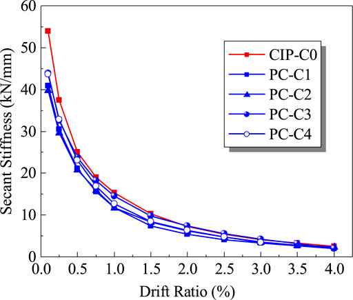
Figure 10. Stiffness reduction varied with drift ratio.
As shown in Figure 10, the average secant stiffness of all columns decreased as the drift ratio increased. Compared to the monolithic column, the precast columns exhibited generally lower overall average secant stiffness, especially in terms of the initial stiffness. However, during early loading phase, the secant stiffness of the monolithic column dropped more rapidly than the precast specimens. As the drift continued to increase, the difference in the secant stiffness between the precast and monolithic columns gradually diminished. By the time the drift ratio reached 2%, the secant stiffness of the precast columns was almost identical to that of the monolithic column.
In the precast columns, the presence of the cold joint near the base appeared to result in lower initial stiffness. Conversely, the monolithically cast column, free from a cold joint, exhibited stronger initial stiffness. However, at higher drift ratios, the CIP column experienced severe concrete crushing, leading to a loss of confinement (as previously discussed) and causing a more rapid degradation in stiffness.
At the same lateral displacement level, the maximum load sustained by a concrete specimen decreases as the number of hysteresis loops increases. This phenomenon, commonly referred to as in-cycle strength degradation (or simply strength degradation), was assessed by the strength degradation coefficient λ (Paulay and Priestley, 1992), which is determined by the ratio of the second peak load to the first peak load at the same drift ratio (namely, λ = Vi, 2nd/Vi, 1st, where Vi, 2nd and Vi, 1st are, respectively, the foresaid second peak load and the first peak load at the same drift ratio i). The values of λ for each specimen are presented in Figure 11.
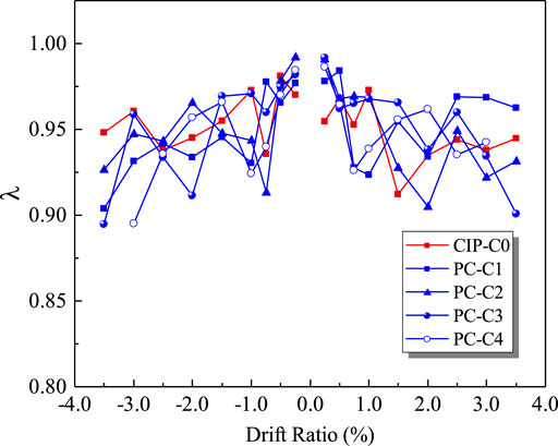
Figure 11. Strength decay varied with drift ratio.
As illustrated in Figure 11, before the drift ratio reached 0.5%, the λ values for all specimens were generally higher than 0.95, indicating that the specimens exhibited minimal damage at this stage, with the in-cycle strength reduction rate not exceeding 5%. Beyond this point, the in-cycle strength loss became more pronounced as the drift ratio increased for all specimens.
For the precast columns, the lowest λ values ranged between 0.89 and 0.94. This suggests that even when the corner longitudinal rebars of the precast columns fractured, the strength reduction at the same drift level remained limited. However, a subtle trend can be observed from Figure 10: at larger drift ratios, the in-cycle strength deterioration of the CIP-C0 column appears to be less significant compared to the precast specimens.
A plausible explanation for this trend lies in the reloading stiffness of CIP-C0, which consistently remained higher than that of the precast specimens, likely due to the absence of the cold joint. This higher stiffness allowed CIP-C0 to retain more strength within the same hysteresis loop at a given deformation level. Nevertheless, this advantage diminished as CIP-C0 exhibited a steeper descending branch in the post-peak region, reflecting its rapid strength deterioration under larger drift demands.
As the drift ratio increased, the energy dissipation capacity of each specimen, represented by the area enclosed by the hysteresis loops, is shown in Figure 12. The results indicate that, prior to a drift ratio 2.5%, the energy dissipation capacity of the precast columns consistently exceeded that of the monolithically cast column. However, beyond that drift ratio, specimen PC-C1, due to the severe buckling of the welded steel tubes, exhibited a slightly lower energy dissipation capacity compared to CIP-C0. Despite this, the overall energy dissipation performance of the precast columns remained comparable to, and in some cases exceeded, that of the monolithic column.
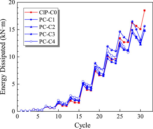
Figure 12. Evolution of energy absorption.
A similar trend is observed in the equivalent viscous damping ratio, ξeq, as shown in Figure 13 and Table 4. These results further corroborate the conclusion that the precast columns exhibited favorable hysteretic behavior under cyclic loading.
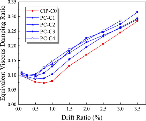
Figure 13. Values of ξeq varied with drift ratio.
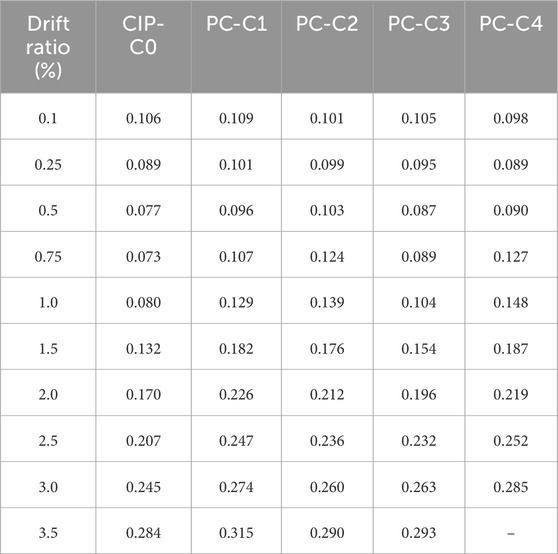
Table 4. Comparison of ξeq at different drift ratios.
The above desirable energy dissipation capacity observed in the precast columns was probably related to the additional confinement provided by the welded steel tubes. These tubes reduced the severity of concrete spalling and crushing, thereby enhancing the hysteretic behavior and allowing the precast columns to sustain greater energy dissipation during loading cycles. Additionally, the more extensive damage along the column shaft also appeared to contribute to enhanced energy dissipation.
It is important to reiterate that grout-filled sleeve connections have been shown to perform well under seismic loading, as noted in the Introduction section; however, scholars have also reported that these connections may exhibit reduced displacement ductility compared to monolithic connections (Haber et al., 2014; Tazarv, 2014; Ameli et al., 2015; 2016; Al-Jelawy et al., 2018). In contrast, the proposed welded steel tube connection demonstrated comparable ductility and energy dissipation to the CIP specimen, even under varying rebar anchorage ratios. Specifically, in terms of the value of ξeq, Al-Jelawy et al. (2018) reported that for precast columns employing grout-filled sleeves, ξeq did not exceed 0.25 up to the point of failure. In comparison, the precast columns in this study achieved a maximum ξeq value of 0.32, clearly demonstrating superior energy dissipation capacity. This is precisely one of the key advantages of the proposed connection.
Plastic hinge deformations in concrete columns are critical in assessing their seismic performance. These deformations result from a combination of flexural displacements, shear deformations (if present), and localized rotations caused by bond slip of longitudinal rebars, which are strongly influenced by strain penetration into the foundation beam.
In the current tests, the plastic hinge deformations were quantified using the instrumentation configuration illustrated in Figure 6. The individual displacement components for each column are presented in Figure 14, divided into four regions, S1 through S4, which contributed varying proportions to the lateral deformation at the column tip. The unknown errors in the figure likely resulted from measurement inaccuracies or unmonitored shear deformations, among other factors.
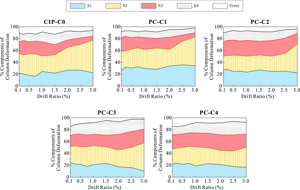
Figure 14. Deformation components of each column.
For the CIP column, it is evident that regions S1 and S2 contributed the most to the overall column tip deformation. At higher levels of lateral deformation, their combined contribution reached up to 70%. Notably, S2 alone contributed more than 40%, while S1 (associated with bond slip) accounted for over 20%. These findings are consistent with the experimental observations, where damages primarily occurred within approximately 300 mm from the column base. It is important to note that bond slip contributions exceeding 20% are not uncommon; several studies (e.g., Bae and Bayrak, 2008; Al-Jelawy et al., 2018) have reported that bond slip is a key contributor to column tip displacement, accounting for up to 50% of total deformation in some monolithic columns.
When it comes to the precast columns (except PC-C1), the combined contributions of S1 and S2 were generally lower than those in the CIP column. Instead, the contributions of S3 and S4 increased significantly. For instance, in PC-C3, the contributions of S3 and S4 to lateral displacement exceeded 40%. This is in agreement with the experimental observations. The use of welded steel tubes and well-anchored column rebars in the precast columns led to more extensive damage zones further from the column base, which explains the increased weight carried by regions S3 and S4.
For PC-C1, where the longitudinal rebars did not run down into the foundation, the primary load transfer mechanism was through the welded steel tubes. Because of that, the contribution of S1 was the highest among all columns (note: for the precast columns, a portion of the S1 deformation may have originated from local buckling of the welded steel tubes). At the same time, the contributions of S3 and S4 were smaller, with S2 contributing the most.
In the other precast columns, the contribution of S3 (primarily corresponding to the region 220 mm above the welded steel tubes) was significant. For PC-C3 and PC-C4, S3 alone contributed more than 20% of the lateral deformation. Accordingly, the contribution of S1 in these columns dropped off, gradually falling below 20% in the later stages of loading.
Tensile strains measured from the longitudinal rebars and welded steel tubes (where applicable) offer valuable insight into the extent and distribution of plasticity along the column shafts. The tensile strain profiles for each column specimen are presented in Figure 15, up to the drift ratio where the measured data remained reliable.
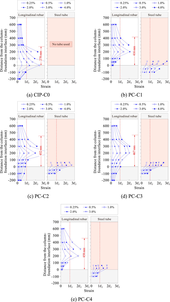
Figure 15. Strain profiles of longitudinal rebars and steel tubes at different drift ratios. (A) CIP-C0 (B) PC-C1 (C) PC-C2 (D) PC-C3 (E) PC-C4.
As expected, the CIP column (Figure 15A) developed plasticity primarily concentrated in the lower portion of the column, with some spreading into the foundation beam. In contrast, for the precast columns, yielding of the longitudinal rebars was observed above the welded tubes, and the plasticity continued to propagate upward along the column shaft as the drift levels increased.
For PC-C1, the steel tube yielded relatively early, at a drift ratio of 0.5%. This early yielding was likely due to the absence of anchored longitudinal rebars, which caused the welded steel tubes to bear the majority of the stresses. As the proportion of longitudinal rebars anchored into the foundation increased (e.g., PC-C2 and PC-C3), the high-stress concentration in the steel tubes was alleviated, and the tensile stresses in the longitudinal rebars were distributed more uniformly. This trend highlights the synergistic role of anchored rebars and steel tubes in managing stress distribution and delaying the progression of plasticity.
Similarly, an increase in steel tube thickness delayed the onset of yielding. By comparing the strain distributions in PC-C1 (4 mm thick steel tubes) and PC-C4 (8 mm thick steel tubes), it is evident that the thicker tubes effectively postponed yielding and reduced stress concentrations in the steel tubes. This delayed yielding underscores the importance of tube thickness in influencing the progression of plasticity within the column shaft.
The determination of plastic hinge length is essential for both seismic modeling and performance evaluation of concrete columns. For the column-to-column connection proposed in this study—which employs welding-spliced steel tubes—the plastic hinge length tends to be longer than that of conventional CIP columns. This section evaluates the plastic hinge lengths of the tested columns using existing prediction formulas.
The plastic hinge length, LP, can be calculated using the formulas proposed by Paulay and Priestley (1992), Lu et al. (2005), and Ning and Li (2016), which are expressed in Equations 2a–2c:
where L = the column length; H = the section height; db and fy = the diameter and the yield stress of the longitudinal rebars, respectively; P and P0 = the applied axial load and the axial load capacity of the column, respectively.
For the tested columns, the plastic hinge lengths were determined by analyzing the strain profiles and applying linear interpolation to estimate the length (Al-Jelawy et al., 2018). The measured plastic hinge lengths for each column are illustrated in Figure 15. To account for the effect of the welding-spliced steel tubes, the calculated LP values were adjusted by adding the length of the welded tubes (180 mm). This adjustment reflects the contribution of localized strengthening provided by the welded tubes to the overall plastic hinge behavior.
Table 5 compares the measured plastic hinge lengths with those predicted using the aforementioned models. As can be observed, the model proposed by Lu et al. (2005) consistently underestimated the plastic hinge lengths for the tested columns. Conversely, the model by Ning and Li (2016) tended to overestimate the plastic hinge lengths. Despite its simplicity, the classic model by Paulay and Priestley (1992) provided the most accurate predictions among the three models evaluated.
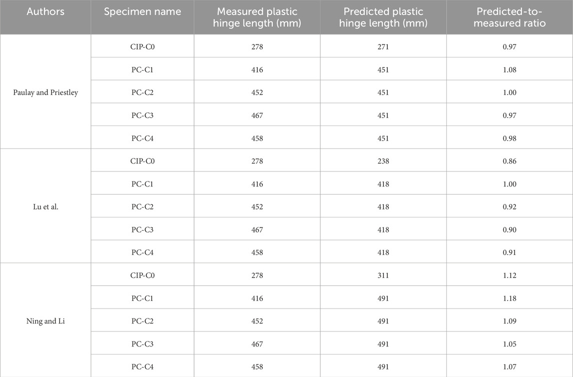
Table 5. Comparison of measured and predicted plastic hinge lengths.
The discrepancies between measured and predicted values are not unexpected, given the inherent uncertainties associated with both measurement and modeling of plastic hinge lengths (Feng et al., 2021). Variability in column geometry, material properties, and the complex behavior of concrete under cyclic inelastic loading contribute to these differences. Moreover, the unique characteristics of the welding-spliced tubes in the precast columns, such as localized buckling, rebar anchorage effects, and strain penetration, introduce additional variables not fully captured by the prediction models.
Nevertheless, the relatively accurate predictions offered by the Paulay and Priestley model suggest that, for precast columns incorporating welding-spliced tubes, the plastic hinge length can be effectively estimated by adding the length of the welded tubes to the model’s predicted values. This approach provides a practical method for approximating plastic hinge behavior in such systems while acknowledging the limitations of existing models in capturing the full complexity of the connection’s behavior.
The post-yield deformation capacity of the proposed columns was evaluated by comparing the envelope curves obtained from the test results with the force-deformation relationships specified for reinforced concrete columns in ASCE 41-17 (2017). The envelope curves in the tests were generated by plotting the peak displacement points from the first cycle at each incremental drift ratio, providing a clear representation of the columns’ deformation behavior under cyclic inelastic loading.
Figure 16 illustrates the envelope curves derived from the tests alongside the predictions made by ASCE 41-17. It is evident that ASCE 41-17 accurately predicts the initial stiffness for all specimens. However, its estimates of post-peak strength decay tend to be conservative, particularly underestimating the residual strength of the columns.
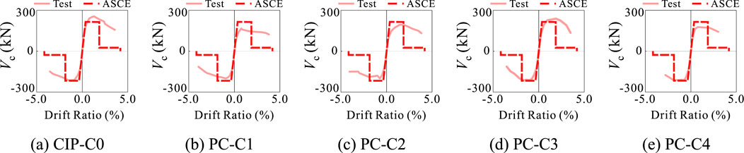
Figure 16. Envelope curves of tests compared with ASCE 41-17. (A) CIP-C0 (B) PC-C1 (C) PC-C2 (D) PC-C3 (E) PC-C4.
For the CIP column, the lateral capacity predicted by ASCE 41-17 is slightly conservative but remains reasonably accurate. In the case of the precast columns with anchored longitudinal rebars, the predicted lateral capacities align closely with the experimental results, demonstrating the reliability of the ASCE 41-17 provisions for these configurations. Conversely, for the precast columns without anchored longitudinal rebars, the strength predictions by ASCE 41-17 were less reliable, leaning towards unsafe estimates.
To predict the lateral load-bearing capacity of the tested columns, a sectional analysis method was first employed to estimate the lateral strength of the monolithic column specimen. Following this, considering the influence of the anchorage ratio of column longitudinal rebars on the lateral capacity of the precast columns, the following empirical formula is suggested:
where VPC represents the lateral strength of the precast column using welded steel tube connections, and ϕ is a strength reduction factor that accounts for the anchorage ratio of the column longitudinal rebars. This factor is suggested to take as 1.0 when the anchorage ratio is 1, 0.9 when it is 1/3, and 0.85 when no rebars are anchored. VCIP is the predicted lateral strength of the CIP column obtained through sectional analysis.
The comparison between the measured and predicted lateral capacities of the tested specimens, based on the empirical formula, is summarized in Table 6. As illustrated, the results demonstrate that this prediction method provides conservative estimates for the lateral strength of the precast columns using welded steel tube connections.
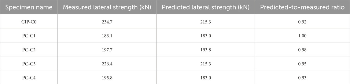
Table 6. Prediction of lateral strength of tested columns.
It is important to emphasize that, due to the limited number of tested specimens in this study, additional experimental investigations are necessary to further validate the reliability of the proposed formula.
For monolithically cast columns, sectional analysis is relatively straightforward because the continuous nature of the longitudinal reinforcement enables efficient stress transfer between the lower and upper columns. However, for precast columns incorporating welding-spliced steel tubes, the anchorage condition of the longitudinal rebars is a key factor affecting the overall performance.
When the column longitudinal rebars are not properly anchored, the column’s flexural capacity is substantially reduced due to the compromised ability of the reinforcement to transfer tensile forces. The empirical factor, ϕ, introduced in the empirical formula captures this anchorage-dependent behavior by adjusting the predicted capacity according to the degree of rebar anchorage, thereby reflecting the importance of proper anchorage detailing in achieving reliable performance.
Finally, the fiber beam-column element in the OpenSEES software (Mazzoni et al., 2007) was employed to simulate the hysteretic behavior of the tested specimens. In the case of the CIP-C0 specimen, the Concrete_02 and Steel_02 material models were used to represent the column concrete and longitudinal reinforcement, respectively. The determination of these material parameters followed the methodology outlined in Yassin’s doctoral dissertation (Yassin, 1994). For the precast column specimens, their hysteretic responses were approximated by scaling the curves obtained by OpenSEES for CIP-C0, using the reduction factor ϕ specified in Equation 3.
Figure 17 presents a comparison between the experimental and simulated hysteresis curves for all tested specimens. As shown in the figure, the fiber beam-column model accurately captures the hysteretic response of CIP-C0, particularly in the post-peak regime where the descending slope aligns well with the experimental data. For the precast specimens, the simulated hysteresis response, derived using the reduction factor, exhibits an acceptable level of agreement with the experimental results. Interestingly, for the precast columns, the descending branch of the simulated curves is steeper than that observed in the experimental data. This discrepancy indirectly suggests that the precast specimens possess better ductility, as they are capable of sustaining greater deformation before a rapid loss of strength.
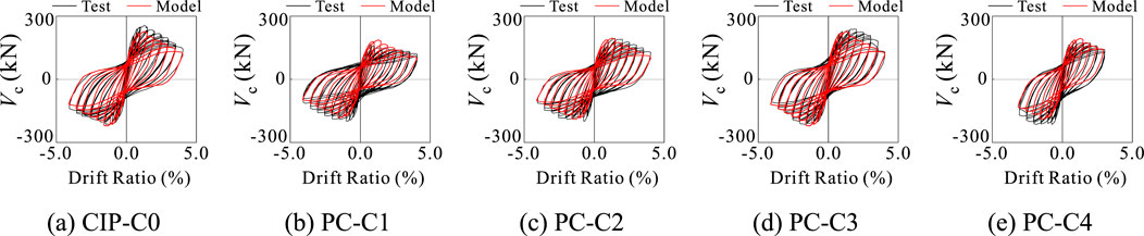
Figure 17. Modeling results of load-displacement responses of specimens using OpenSEES model. (A) CIP-C0 (B) PC-C1 (C) PC-C2 (D) PC-C3 (E) PC-C4.
This paper proposes an innovative emulative hybrid column-to-column connection by means of applying welding-spliced steel tubes. Compared to grout-filled sleeve connections, the proposed method demonstrates the following advantages and limitations:
(a) Improved constructability: Grout-filled sleeves typically require precise alignment and high-quality grouting under controlled conditions to ensure proper load transfer. On-site challenges, such as inconsistent grouting quality or difficulties in inspection, can negatively impact their reliability. In contrast, the proposed connection offers a simpler construction process, with welding being much more familiar to construction teams and easier to inspect. In addition, the high precision inherent in steel fabrication enhances the feasibility of executing this connection. Another particularly notable advantage is that the columns can be quickly secured through tack welding of the steel tubes, eliminating the need for temporary construction supports that are often required for grout-filled sleeve connections;
(b) Enhanced ductility: While grout-filled sleeve connections may exhibit reduced displacement ductility compared to monolithic connections, the proposed welded steel tube connection demonstrated comparable ductility and energy dissipation to cast-in-place connections, even under varying rebar anchorage ratios. This highlights the ability of the proposed system to maintain robust seismic performance.
(a) Cold joint issues: The interface between the post-cast concrete and the precast sections forms a cold joint, which may compromise the reliability of load transfer and reduce the overall load-bearing capacity of the connection. To mitigate this, column longitudinal rebars should be extended into the joint region, which however introduces logistical challenges during transportation and handling of the precast columns;
(b) Dependence on welding: Similar to grout-filled sleeve connections, the proposed method depends on weather conditions due to its reliance on on-site welding. Additionally, welding may introduce residual stresses, which could have adverse effects on long-term performance;
(c) Localized stiffening effect: The inclusion of welded steel tubes introduces localized stiffening, which shifts the plastic hinge region upward along the column shaft. This modification results in a wider plastic deformation zone, potentially complicating post-earthquake repair efforts.
After considering these advantages and limitations, the key findings of this study are summarized as follows:
(1) When column longitudinal rebars are well anchored, the cyclic behaviors of the precast columns with welded steel tubes are comparable to that of the CIP column. The welds between the steel tubes performed reliably, with no defects or fractures observed during testing. Additionally, the deformation capacity and energy dissipation ability of the precast columns are comparable to, or even better than, their CIP counterpart. The ability of the precast columns to retain similar stiffness to the CIP column after large inelastic excursions highlights the potential of the proposed connection in seismic applications;
(2) The welded steel tubes alter the failure mechanism of the precast columns, resulting in pronounced damage at higher regions along the column shaft. This upward shift in the plastic hinge zone reflects the influence of localized strengthening on the damage distribution and extent;
(3) The test results also indicate that the precast columns without adequate rebar anchorage struggle to achieve the same level of lateral strength as the monolithic column. To avoid this, it is recommended that, in addition to the welded steel tubes, at least four corner longitudinal rebars of the upper column be extended into the lower column’s steel tube. This is essential for the proposed connection because the extension of rebars is capable of ensuring force transfer and providing additional structural integrity;
(4) The empirical method proposed in this study provides a conservative estimate of the lateral load-bearing capacity of the precast columns using welded steel tubes. Additionally, the plastic hinge length of the precast columns can be reasonably estimated by adding the length of the welded tubes to the predicted values from the Paulay and Priestley model.
While this study provides some new insights, the following limitations are acknowledged:
(i) The testing matrix in this study only consists of a limited number of specimens. As a result, the findings presented are based on the specific configuration and test conditions employed, which may not fully capture the behavior of the proposed connection system under broader design scenarios. Future studies will aim to expand the testing matrix by including variations in parameters such as axial load ratio, column dimensions, and connection details, thereby allowing for validation of the conclusions and further increasing their practical value as engineering design guidelines;
(ii) The phenomenon-based nature of the empirical formula proposed in this study provides a safety margin in design. However, as with any empirical model, its applicability must be validated by a broader range of test conditions to ensure its robustness in differing structural configurations and loading scenarios;
(iii) The proposed connection method lacks detailed finite element simulations, primarily due to two significant obstacles: First, the mechanical behavior of the cold joint interface remains poorly understood, with no experimental data currently available to support accurate modeling. Second, the splice relationship between the downward-extended column rebars and the steel tubes involves a non-contact condition that has not yet been thoroughly investigated through experimental studies. Given these challenges, future research should prioritize addressing these issues by conducting experimental studies and developing advanced numerical modeling techniques to better understand those complex interactions;
(iv) Further improvements in experimental observations, particularly in capturing crack patterns, are needed. Techniques such as Digital Image Correlation (DIC) techniques (Mata-Falcón et al., 2020) or the application of fractal theory and optical-digital diagnosis methods (Maruschak et al., 2012) could be employed to better analyze crack networks and other localized deformation behaviors, thereby providing a deeper understanding of the connection’s cyclic response.
Overall, the findings from this study highlight several important aspects regarding the seismic performance of the proposed hybrid connection. The observed upward shift of the plastic hinge zone suggests that the plastic deformation behavior of the precast columns differs significantly from that of traditional CIP columns. The use of welded steel tubes introduces localized stiffening, which, while beneficial in some respects, may lead to widely-distributed plasticity, causing more spread of failure. Furthermore, the results indicate that simply increasing the tube thickness is not a substitute for proper anchorage detailing. Engineers must ensure that both the steel tube and the anchorage of longitudinal rebars are carefully designed to work together to resist lateral forces effectively.
The raw data supporting the conclusions of this article will be made available by the authors, without undue reservation.
M-MJ: Conceptualization, Funding acquisition, Investigation, Methodology, Writing–review and editing. WC: Investigation, Writing–review and editing. SZ: Data curation, Investigation, Validation, Writing–review and editing. YX: Investigation, Methodology, Validation, Writing–review and editing. X-YZ: Conceptualization, Funding acquisition, Investigation, Methodology, Project administration, Supervision, Writing–original draft.
The author(s) declare that financial support was received for the research, authorship, and/or publication of this article. This research is financially supported by Science and Technology Program of Guangzhou Municipal Construction Group Co., Ltd ([2019]-KJ007, [2021]-KJ035), China’s National Natural Science Foundation (52378155), and by the Special Funds for Guangdong’s Provincial Science and Technology Innovation Strategy (2024A1515011382). The funder was not involved in the study design, data collection, analysis, interpretation of data, writing of this article, or the decision to submit it for publication.
Authors M-MJ and WC were employed by Guangzhou Engineering Contractor Group Co., Ltd.
The remaining authors declare that the research was conducted in the absence of any commercial or financial relationships that could be construed as a potential conflict of interest.
The author(s) declare that no Generative AI was used in the creation of this manuscript.
All claims expressed in this article are solely those of the authors and do not necessarily represent those of their affiliated organizations, or those of the publisher, the editors and the reviewers. Any product that may be evaluated in this article, or claim that may be made by its manufacturer, is not guaranteed or endorsed by the publisher.
ACI 374.1-05 (2005). Acceptance criteria for moment frames based on structural testing and commentary (Reapproved 2019). Farmington Hills, MI, USA: ACI American Concrete Institute.
ACI 550R-96 (2001). Design recommendations for precast concrete structures (Reapproved 2001). Farmington Hills, MI, USA: ACI American Concrete Institute.
Ahn, S. R., Sung, H. S., and Kang, T. H. (2023). Structural performance of precast concrete column joint with clamped headed bar during construction. ACI Struct. J. 120 (3), 245–256. doi:10.14359/51738667
Albright, A., Argentoni, A., and Calvi, P. M. (2022). Experimental behavior of interior and exterior steel-concrete composite NPS® beam-column joints. Eng. Struct. 251, 113589. doi:10.1016/j.engstruct.2021.113589
Al-Jelawy, H. M., Mackie, K. R., and Haber, Z. B. (2018). Shifted plastic hinging for grouted sleeve column connections. ACI Struct. J. 115 (4), 1101–1114. doi:10.14359/51702233
Ameli, M. J., Brown, D. N., Parks, J. E., and Pantelides, C. P. (2016). Seismic column-to-footing connections using grouted splice sleeves. ACI Struct. J. 113 (5), 1021–1030. doi:10.14359/51688755
Ameli, M. J., Parks, J. E., Brown, D. N., and Pantelides, C. P. (2015). Seismic evaluation of grouted splice sleeve connections for reinforced precast concrete column-to-cap beam joints in accelerated bridge construction. PCI J. 60 (2), 80–103. doi:10.15554/pcij.03012015.80.103
ASCE/SEI 41-17 (2017). Seismic rehabilitation of existing buildings. Reston, VA, USA: ASCE American Society of Civil Engineers.
Bae, S., and Bayrak, O. (2008). Plastic hinge length of reinforced concrete columns. ACI Struct. J. 105 (3), 290–300. doi:10.14359/19788
Baran, E., Mahamid, M., Baran, M., Kurtoglu, M., and Torra-Bilal, I. (2021). Performance of a moment resisting beam-column connection for precast concrete construction. Eng. Struct. 246, 113005. doi:10.1016/j.engstruct.2021.113005
Bhatt, P., and Kirk, D. W. (1985). Tests on an improved beam column connection for precast concrete. ACI Struct. J. 82 (6), 834–843. doi:10.14359/10395
Cai, X., Gong, N., Fu, C., Zhu, Y., and Wu, J. (2021). Seismic behavior of self-centering prestressed precast concrete frame subassembly using steel top and seat angles. Eng. Struct. 229, 111646. doi:10.1016/j.engstruct.2020.111646
Choi, H. K., Choi, Y. C., and Choi, C. S. (2013). Development and testing of precast concrete beam-to-column connections. Eng. Struct. 56, 1820–1835. doi:10.1016/j.engstruct.2013.07.021
Dal Lago, B., Del Galdo, M., and Bisi, D. (2022). Tests and design of welded-bar angle connections of precast floor elements. J. Adv. Concr. Technol. 20 (2), 43–56. doi:10.3151/jact.20.43
Dal Lago, B., Negro, P., and Dal Lago, A. (2018). Seismic design and performance of dry-assembled precast structures with adaptable joints. Soil Dyn. Earthq. Eng. 106, 182–195. doi:10.1016/j.soildyn.2017.12.016
Davaadorj, O., Calvi, P. M., and Stanton, J. F. (2020). Shear stress transfer across concrete-to-concrete interfaces: experimental evidence and available strength models. PCI J. 65 (4), 87–111. doi:10.15554/pcij65.4-04
Durgarian, C., Farley, B., Fortenberry, A., Harris, C., Kusznir, B., Wilden, H., et al. (2022). Structural grouting of load-bearing precast concrete elements: issues and solutions. PCI J. 67 (1), 25–43. doi:10.15554/pcij67.1-03
Einea, A., Yamane, T., and Tadros, M. K. (1995). Grout-filled pipe splices for precast concrete construction. PCI J. 40 (1), 82–93. doi:10.15554/pcij.01011995.82.93
Elliott, K. S., and Jolly, C. (2013). Multi-storey precast concrete framed structures. 2nd Edition. New York: John Wiley and Sons.
Englekirk, R. E. (2003). Seismic design of reinforced and precast concrete buildings. New York: John Wiley and Sons.
Ersoy, U., and Tankut, T. (1993). Precast concrete members with welded plate connections under reversed cyclic loading. PCI J. 38 (4), 94–100. doi:10.15554/pcij.07011993.94.100
Fan, J., Feng, D., Wu, G., Hou, S., and Lu, Y. (2020). Experimental study of prefabricated RC column-foundation assemblies with two different connection methods and using large-diameter reinforcing bars. Eng. Struct. 205, 110075. doi:10.1016/j.engstruct.2019.110075
Feng, D. C., Chen, S. Z., Azadi Kakavand, M. R., and Taciroglu, E. (2021). Probabilistic model based on Bayesian model averaging for predicting the plastic hinge lengths of reinforced concrete columns. J. Eng. Mech. 147 (10), 04021066. doi:10.1061/(ASCE)EM.1943-7889.0001976
GB50011-2010 (2010). Code for seismic design of buildings. Beijing, China: China Building Industry Press.
Ghayeb, H. H., Razak, H. A., and Sulong, N. R. (2017). Development and testing of hybrid precast concrete beam-to-column connections under cyclic loading. Constr. Build. Mater. 151, 258–278. doi:10.1016/j.conbuildmat.2017.06.073
Ghayeb, H. H., Razak, H. A., and Sulong, N. R. (2020a). Seismic performance of innovative hybrid precast reinforced concrete beam-to-column connections. Eng. Struct. 202, 109886. doi:10.1016/j.engstruct.2019.109886
Ghayeb, H. H., Razak, H. A., and Sulong, N. R. (2020b). Performance of dowel beam-to-column connections for precast concrete systems under seismic loads: a review. Constr. Build. Mater. 237, 117582. doi:10.1016/j.conbuildmat.2019.117582
Ghayeb, H. H., Sulong, N. R., Razak, H. A., Mo, K. H., Ismail, Z., Hashim, H., et al. (2023). A review of the seismic performance behaviour of hybrid precast beam-to-column connections. Archives Civ. Mech. Eng. 23 (1), 35. doi:10.1007/s43452-022-00558-7
Girgin, S. C., Misir, I. S., and Kahraman, S. (2017). Experimental cyclic behavior of precast hybrid beam-column connections with welded components. Int. J. Concr. Struct. Mater. 11, 229–245. doi:10.1007/s40069-017-0190-y
Guan, M., Xiao, J., Wang, Y., Zhang, Y., Liang, Z., and Lai, Z. (2023). Seismic behavior of innovative precast hybrid steel reinforced concrete beam-column connections. J. Constr. Steel Res. 203, 107817. doi:10.1016/j.jcsr.2023.107817
Guaygua, B., Sánchez-Garrido, A. J., and Yepes, V. (2023). A systematic review of seismic-resistant precast concrete buildings. Structures 58, 105598. doi:10.1016/j.istruc.2023.105598
Haber, Z. B., Saiidi, M. S., and Sanders, D. H. (2014). Seismic performance of precast columns with mechanically spliced column-footing connections. ACI Struct. J. 111 (3), 639–650. doi:10.14359/51686624
Han, W., Zhao, Z., Qian, J., Cui, Y., and Liu, S. (2018). Seismic behavior of precast columns with large-spacing and high-strength longitudinal rebars spliced by epoxy mortar-filled threaded couplers. Eng. Struct. 176, 349–360. doi:10.1016/j.engstruct.2018.09.007
Henin, E., and Morcous, G. (2015). Non-proprietary bar splice sleeve for precast concrete construction. Eng. Struct. 83, 154–162. doi:10.1016/j.engstruct.2014.10.045
Hong, J., Shen, G. Q., Li, Z., Zhang, B., and Zhang, W. (2018). Barriers to promoting prefabricated construction in China: a cost-benefit analysis. J. Clean. Prod. 172, 649–660. doi:10.1016/j.jclepro.2017.10.171
Hu, G., Zhang, Z., Cao, B., Pan, Z., and Zeng, L. (2024). Seismic behavior of precast concrete beam-column joints with bending moment-shear separation controllable plastic hinge. Eng. Struct. 304, 117585. doi:10.1016/j.engstruct.2024.117585
Khaloo, A. R., and Parastesh, H. (2003). Cyclic loading response of simple moment-resisting precast concrete beam-column connection. ACI Struct. J. 100 (4), 440–445. doi:10.14359/12652
Kim, J., Lee, D., Choi, S., Jeong, H., and Kim, K. (2022). Seismic performance of precast multi-span frame system integrated by unbonded tendons. ACI Struct. J. 119 (5), 193–206. doi:10.14359/51734801
Kim, S., Kang, T., Jung, D., and LaFave, J. M. (2021). Seismic behavior of precast and post-tensioned exterior connections with ductile headed rods. ACI Struct. J. 118 (1), 87–100. doi:10.14359/51728179
Kishen, J. C., and Rao, P. S. (2007). Fracture of cold jointed concrete interfaces. Eng. Fract. Mech. 74 (1-2), 122–131. doi:10.1016/j.engfracmech.2006.01.017
Korkmaz, H. H., and Tankut, T. (2005). Performance of a precast concrete beam-to-beam connection subject to reversed cyclic loading. Eng. Struct. 27 (9), 1392–1407. doi:10.1016/j.engstruct.2005.04.004
Kurama, Y. C., Sritharan, S., Fleischman, R. B., Restrepo, J. I., Henry, R. S., Cleland, N. M., et al. (2018). Seismic-resistant precast concrete structures: State of the art. J. Struct. Eng. 144 (4), 03118001. doi:10.1061/(asce)st.1943-541x.0001972
Lee, T. H., Choi, S. J., Yang, D. H., and Kim, J. H. J. (2022). Experimental seismic structural performance evaluations of RC columns strengthened by stiff-type polyurea. Int. J. Concr. Struct. Mater. 16 (1), 65. doi:10.1186/s40069-022-00552-6
Li, B., Kulkarni, S. A., and Leong, C. L. (2009). Seismic performance of precast hybrid-steel concrete connections. J. Earthq. Eng. 13 (5), 667–689. doi:10.1080/13632460902837793
Li, X., Xiao, S., Gao, R., Harries, K. A., Wang, Z., and Xu, Q. (2021). Effects of grout sleeve defects and their repair on the seismic performance of precast concrete frame structures. Eng. Struct. 242, 112619. doi:10.1016/j.engstruct.2021.112619
Liu, H., Wang, Z., Xu, C., and Du, X. (2021). Influence of axial compression ratio on the seismic performance of precast columns with grouted sleeve connections. J. Struct. Eng. 147 (12), 04021194. doi:10.1061/(asce)st.1943-541x.0003118
Lu, Y., Gu, X., and Guan, J. (2005). Probabilistic drift limits and performance evaluation of reinforced concrete columns. J. Struct. Eng. 131 (6), 966–978. doi:10.1061/(ASCE)0733-9445(2005)131:6(966)
Ma, F., Deng, M., Ma, Y., Lü, H., Yang, Y., and Sun, H. (2021). Experimental study on interior precast concrete beam–column connections with lap-spliced steel bars in field-cast RPC. Eng. Struct. 228, 111481. doi:10.1016/j.engstruct.2020.111481
Maruschak, P. O., Konovalenko, I. V., and Bishchak, R. T. (2012). Effect of thermal fatigue cracks on brittle-ductile deformation and failure of cbcm roller surface layers. Metallurgist 56 (1), 30–36. doi:10.1007/s11015-012-9532-9
Mata-Falcón, J., Haefliger, S., Lee, M., Galkovski, T., and Gehri, N. (2020). Combined application of distributed fibre optical and digital image correlation measurements to structural concrete experiments. Eng. Struct. 225, 111309. doi:10.1016/j.engstruct.2020.111309
Mazzoni, S., Mckenna, F., Scott, M. H., and Fenves, G. L. (2007). “The OpenSees command language manual, version 2.0,” in Pacific earthquake engineering research center. Berkeley, CA: University of California.
Menegon, S. J., Wilson, J. L., Lam, N. T., and Gad, E. F. (2020). Experimental testing of innovative panel-to-panel connections for precast concrete building cores. Eng. Struct. 207, 110239. doi:10.1016/j.engstruct.2020.110239
Naito, C. J., Zimpfer, J., Sause, R., and Kaufmann, E. (2012). Effect of environmental conditions on field welding of precast concrete connections. PCI J. 57 (2), 142–161. doi:10.15554/pcij.03012012.142.161
Nascimbene, R., and Bianco, L. (2021). Cyclic response of column to foundation connections of reinforced concrete precast structures: numerical and experimental comparisons. Eng. Struct. 247, 113214. doi:10.1016/j.engstruct.2021.113214
Ning, C. L., and Li, B. (2016). Probabilistic approach for estimating plastic hinge length of reinforced concrete columns. J. Struct. Eng. 142 (3), 04015164. doi:10.1061/(asce)st.1943-541x.0001436
Park, R., Priestley, M. J. N., and Gill, W. D. (1982). Ductility of square-confined concrete columns. J. Struct. Div. 108 (4), 929–950. doi:10.1061/JSDEAG.0005933
Paulay, T., and Priestley, M. J. N. (1992). Seismic design of reinforced concrete and masonry buildings. New York: John Wiley and Sons.
Pillai, S. U., and Kirk, D. W. (1981). Ductile beam-column connection in precast concrete. ACI Struct. J. 78 (6), 480–487. doi:10.14359/10926
Qing, Y., Wang, C., Meng, S., and Zeng, B. (2022). Experimental study on the seismic performance of precast concrete columns with thread-bolt combination couplers. Eng. Struct. 251, 113461. doi:10.1016/j.engstruct.2021.113461
Quiel, S. E., Naito, C. J., and Fallon, C. T. (2019). A non-emulative moment connection for progressive collapse resistance in precast concrete building frames. Eng. Struct. 179, 174–188. doi:10.1016/j.engstruct.2018.10.027
Rodríguez, M. E., and Torres-Matos, M. (2013). Seismic behavior of a type of welded precast concrete beam-column connection. PCI J. 58 (3), 81–94. doi:10.15554/pcij.06012013.81.94
Senturk, M., Pul, S., Ilki, A., and Hajirasouliha, I. (2020). Development of a monolithic-like precast beam-column moment connection: experimental and analytical investigation. Eng. Struct. 205, 110057. oi.org/. doi:10.1016/j.engstruct.2019.110057
Stone, W. C., Cheok, G. S., and Stanton, J. F. (1995). Performance of hybrid moment-resisting precast beam-column concrete connections subjected to cyclic loading. ACI Struct. J. 92 (2), 229–249. doi:10.14359/1145
Tazarv, M. (2014). Next generation of bridge columns for accelerated bridge construction in high seismic zones. Reno: University of Nevada.
Tullini, N., and Minghini, F. (2016). Grouted sleeve connections used in precast reinforced concrete construction–Experimental investigation of a column-to-column joint. Eng. Struct. 127, 784–803. doi:10.1016/j.engstruct.2016.09.021
Vidjeapriya, R., and Jaya, K. P. (2013). Experimental study on two simple mechanical precast beam-column connections under reverse cyclic loading. J. Perform. Constr. Facil. 27 (4), 402–414. doi:10.1061/(ASCE)CF.1943-5509.0000324
Wang, H., Marino, E. M., Pan, P., Liu, H., and Nie, X. (2018). Experimental study of a novel precast prestressed reinforced concrete beam-to-column joint. Eng. Struct. 156, 68–81. doi:10.1016/j.engstruct.2017.11.011
Wong, R. W., and Loo, B. P. (2022). Sustainability implications of using precast concrete in construction: an in-depth project-level analysis spanning two decades. J. Clean. Prod. 378, 134486. doi:10.1016/j.jclepro.2022.134486
Xu, L., Pan, J., and Cai, J. (2019). Seismic performance of precast RC and RC/ECC composite columns with grouted sleeve connections. Eng. Struct. 188, 104–110. doi:10.1016/j.engstruct.2019.03.022
Xu, L., Pan, J., and Guo, L. (2022). Mechanical performance of precast RC columns with grouted sleeve connections. Eng. Struct. 252, 113654. doi:10.1016/j.engstruct.2021.113654
Yao, F., Ji, Y., Tong, W., Li, H. X., and Liu, G. (2021). Sensing technology based quality control and warning systems for sleeve grouting of prefabricated buildings. Automation Constr. 123, 103537. doi:10.1016/j.autcon.2020.103537
Yassin, M. H. M. (1994). Nonlinear analysis of prestressed concrete structures under monotonic and cyclic loads. Berkeley: University of California.
Ye, M., Jiang, J., Chen, H. M., Zhou, H. Y., and Song, D. D. (2021). Seismic behavior of an innovative hybrid beam-column connection for precast concrete structures. Eng. Struct. 227, 111436. doi:10.1016/j.engstruct.2020.111436
Yee, A. A. (1962). Composite precast concrete connections. PCI J. 72 (2), 33–48. doi:10.15554/pcij.04011962.33.48
Yee, A. A. (2001b). Social and environmental benefits of precast concrete technology. PCI J. 46 (3), 14–19. doi:10.15554/pcij.05012001.14.19
Yee, A. A. (2001a). Structural and economic benefits of precast/prestressed concrete construction. PCI J. 46 (4), 34–42. doi:10.15554/pcij.07012001.34.42
Yekrangnia, M., Taheri, A., and Zahrai, S. M. (2016). Experimental and numerical evaluation of proposed precast concrete connections. Struct. Concr. 17 (6), 959–971. doi:10.1002/suco.201500168
Zhang, J., Ding, C., Rong, X., Yang, H., Wang, K., and Zhang, B. (2020). Experimental seismic study of precast hybrid SFC/RC beam–column connections with different connection details. Eng. Struct. 208, 110295. doi:10.1016/j.engstruct.2020.110295
Zhang, P., Wang, Z., Ge, J., Yan, X., and Liu, S. (2023). Full-scale experimental study on precast bridge column with grouted sleeve connections and large-diameter reinforcing bars. Eng. Struct. 294, 116747. doi:10.1016/j.engstruct.2023.116747
Zhang, R., Guo, T., Wu, Y., Li, A., Zhang, H., and Yang, T. Y. (2024b). Experimental study and seismic assessment on base isolated precast concrete frame structure with box connectors. Eng. Struct. 321, 119020. doi:10.1016/j.engstruct.2024.119020
Zhang, X., Wang, B., Ju, Y., Wang, D., Han, Y., and Song, Y. (2024a). Seismic performance of precast frame with UHPC composite beams and HSC columns under cyclic loadings. Eng. Struct. 302, 117429. doi:10.1016/j.engstruct.2023.117429
Keywords: precast concrete column, steel tube connection, grouted sleeve, seismic performance, cyclic behavior
Citation: Ji M-M, Chen W, Zeng S, Xiong Y and Zhao X-Y (2025) Cyclic testing of a steel-tube-enabled emulative precast column-to-column connection. Front. Mater. 11:1525718. doi: 10.3389/fmats.2024.1525718
Received: 10 November 2024; Accepted: 23 December 2024;
Published: 08 January 2025.
Edited by:
Adesola Ademiloye, Swansea University, United KingdomReviewed by:
Amir Ali Shahmansouri, Washington State University, United StatesCopyright © 2025 Ji, Chen, Zeng, Xiong and Zhao. This is an open-access article distributed under the terms of the Creative Commons Attribution License (CC BY). The use, distribution or reproduction in other forums is permitted, provided the original author(s) and the copyright owner(s) are credited and that the original publication in this journal is cited, in accordance with accepted academic practice. No use, distribution or reproduction is permitted which does not comply with these terms.
*Correspondence: Yan Xiong, eHlhbkBzY3V0LmVkdS5jbg==; Xin-Yu Zhao, Y3R6aGFveHlAc2N1dC5lZHUuY24=
Disclaimer: All claims expressed in this article are solely those of the authors and do not necessarily represent those of their affiliated organizations, or those of the publisher, the editors and the reviewers. Any product that may be evaluated in this article or claim that may be made by its manufacturer is not guaranteed or endorsed by the publisher.
Research integrity at Frontiers
Learn more about the work of our research integrity team to safeguard the quality of each article we publish.