 Jikai Tang1
 Bin Liu
 Debo Zhao
- 1Guangxi Shangheng Expressway Co., Ltd., Nanning, China
- 2Hualan Design & Consulting Group, Nanning, China
- 3School of Civil Engineering and Architecture, Guangxi Minzu University, Nanning, China
- 4Key Laboratory for Wind and Bridge Engineering of Hunan Province, College of Civil Engineering, Hunan University, Changsha, China
- 5Key Laboratory of Coastal Urban Resilient Infrastructures (MOE), Shenzhen University, Shenzhen, China
Fiber-reinforced polymer (FRP) confined concrete filled steel tube (CFST) structures effectively harness the advantages of FRP materials, improving the performance of CFST structures and overcoming durability issues of steel tubes. Three-dimensional detailed finite element (FE) models are usually employed to estimate the impact-resistant performance of FRP confined CFST members under impact loadings. However, detailed FE models are typically complex in modeling and low in calculation efficiency as well as require high performance in computer hardware. Hence, this paper aims to develop an alternative modeling method that can predict the impact behavior of FRP confined CFST members with high efficiency and low requirements in computer resources. The proposed method includes a contact model using mass-spring-damper elements to describe the contact behavior between the impactor and the impacted FRP confined CFST members and a nonlinear fiber-based beam-column element model to simulate the behavior of FRP-confined CFST members under impact loading. The accuracies of fiber-section beam-column elements are carefully examined for FRP confined CFST members based on quasi-static test data reported in the literature. It is found that the fiber-based elements considering confinement effects provided by FRP and steel tubes can accurately predict the force-deformation relationship of the FRP confined CFST members under monotonic loading. By incorporating the strain-rate effects of concrete, steel, and FRP materials, the validated fiber-section elements are employed to simulate eight impact tests on FRP confined CFST members. Good agreements are observed between the results obtained from the proposed models and the experimental data. The computational efficiency of the developed model is three orders of magnitude faster than that of the conventional detailed FE model.
1 Introduction
Concrete-filled steel tubular (CFST) structures have rapidly developed in the engineering field due to their fast construction speed and excellent mechanical properties, and have been widely used in practical engineering projects. However, CFST structures encounter significant durability challenges (Chen et al., 2015) (Qingli et al., 2013), which limit their utilization in corrosive environments. Scholars have significantly enhanced the corrosion resistance of CFST structures by externally wrapping steel tubes with fiber materials (FRP), thereby enabling their application in corrosive environments such as sea-crossing bridges and offshore projects. (XIAO, 2001) (Fang, 2017).
As a novel structural form, FRP-confined CFST structures fully exploit the advantages of FRP materials, improving the operational performance of CFST structures. In recent years, extensive research has been dedicated to investigating FRP-confined CFST structures, conducting numerous static tests (Wang et al., 2008)- (Zhu et al., 2018) and theoretical analyses (Zhang et al., 2019)- (Teng et al., 2013) to delve into the static bearing characteristics and load mechanisms of FRP-confined CFST structures. However, research on the dynamic performance of this structure is still very limited. In experimental studies, Alam M I (Alam et al., 2017), Shakir, A.S (Shakir et al., 2016), and Chen C (Chen et al., 2011) conducted lateral impact tests on FRP-confined CFST structures using drop-hammer test equipment, demonstrating that the type, strength, thickness, and wrapping direction of FRP significantly influence the dynamic response of FRP-confined CFST structures. Due to the complexity of dynamic impact test equipment and technology, dynamic test equipment is not widespread. Additionally, considering issues such as test safety and high costs, it is impractical to extensively study the structural dynamic behavior through a large number of impact tests. Hence, numerous researchers have developed finite element analysis models to comprehensively explore the dynamic performance of FRP-confined CFST structures under impact loadings (Chen and Yinghua, 2013; Saini and Shafei, 2018; Ziqing et al., 2019). In recent years, much research has been devoted to establishing dynamic analysis models of FRP-confined CFST structures subjected to impact loading. In most of these studies, three-dimensional high-fidelity FE models were developed by using general contact-impact nonlinear FE codes (e.g., LS-DYNA and ABAQUS). Typically, the detailed FE modeling method has demonstrated good accuracy in predicting the impact behavior of structures. However, this method often requires significant investments of time, effort, and computational resources in modeling and analysis (Fan and Yuan, 2014; Wang and Morgenthal, 2017). It is challenging for designers to apply such methods to analyze FRP-confined CFST structures under impact loading in practice, especially during preliminary design iterations or risk-based design processes, which often involve hundreds of thousands of impact event analyses. Furthermore, since FRP is a relatively new material, its three-dimensional dynamic constitutive model has not yet reached maturity. Consequently, the accuracy of the detailed FE modeling method established using existing FRP dynamic constitutive models to predict the dynamic response of FRP-confined CFST structures is often unsatisfactory.
Due to the limitations of current methods, there is a pressing need to devise a practical and efficient analysis approach for evaluating FRP-confined CFST structures under impact loading. Therefore, this study aims to develop a novel analysis method that can accurately and effectively assess the behavior of FRP-confined CFST structures subjected to impact loading. Initially, the proposed analysis method is described. Subsequently, the existing quasi-static tests on FRP-confined CFST columns are utilized to examine the fiber-based beam-column element model of such structures. The validated FRP-confined modeling method is then extended into impact simulations by incorporating strain rate effects of concrete steel and FRP materials. Finally, eight impact tests are collected to validate the rationality of the developed analysis method in this study. The efficient analysis model proposed in this paper has significant advantages such as high efficiency and low requirements of computational and elements, and can be well integrated into risk-based collision design frameworks.
2 Overview of analysis method
In practical engineering, structures may be subjected to impacts from objects such as vessels, vehicles, or falling rocks. For bridge-vessel collision issues, Fan (Fan and Yuan, 2014) and Wang (Wang and Morgenthal, 2017) have used simplified mass-spring-damper elements to create a macroscopic model representing the mechanical properties of vehicles. Modeling about different kinds of impactors is beyond the scope of this study. In order to verify the proposed simulation method in this study, based on drop hammer impact tests, developed a macro-element-based contact model of the impactor using a mass-spring-damper system to simulate the mechanical properties of the drop hammer and the local interaction behavior between drop hammer and FRP-confined CFST structure. As shown in Figure 1, the drop hammer is considered to be a very stiff impact object, therefore, a lumped mass element (A) and an elastic spring element are used to simulate the mass (Mh) and stiffness (Kh) of the drop hammer, respectively. The elastic spring element is a compression-only spring to simulate the separation behavior between the impactor and the impacted structure after a collision.
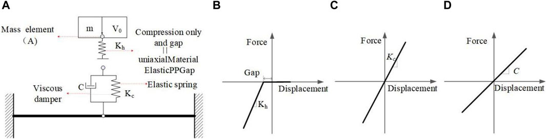
Figure 1. Simplified analysis model of FRP-confined CFST member under impact loading and the constitutive relationship of macro-element. (A) The SDOF impactor and the marcoelement-based contact model. (B) Compression-only elastic spring element. (C) Elastic spring. (D) Viscous damper.
In general, the initial impact energy of the impactor cannot be assigned in implicit solver (e.g., OpenSees) by directly defining the initial impact velocity. Therefore, in this study, the initial impact velocity (V0) is obtained by applying an instantaneous load to the lumped mass based on the impulse theorem (Equation 1). To ensure that the concentrated mass does not interact with the impacted member before obtaining the expected initial impact energy, an initial gap (GA) is added to the compression-only spring. Additionally, the initial gap (GA) should satisfy the requirement in Equation 2. In this study, the simulation process is implemented using the open source analysis platform OpenSees. Specifically, the compression-only spring with an initial gap is defined using the ElasticPPGap material, which can be used to construct an elastic perfectly-plastic gap uniaxial material. Figure 1B presents the force-deformation relationship of the material model ElasticPPGap. Since the stiffness of the drop hammer is generally greater than that of the impacted components, a relatively high value of Kh, set to 2 × 10⁹ N m, is used in this paper.
Where P is the initial step pulse load with time; t is the duration of the pulse load;
Similar to the simplified analysis model established by Fan (Fan and Yuan, 2014), a spring-damping system is used to simulate the local interaction behavior between the impactor and the impacted member. As shown in Figure 1A, The contact model consists of an elastic spring and a viscous damaper in parallel to simulate the contact stiffness (Kc) and contact damping (C) between the impactor and the impacted member, as shown in Figure 1. The values of Kc and C are determined using the method provided in the literature (Ye and Peng, 2006). The modeling of the impacted FRP-confined CFST member is the primary focus of this study, which will be examined in the following section.
3 Fiber-based element model of CFST FRP-confined CFST member
Nonlinear fiber-based beam element models were developed by OpenSees to simulate the behavior of FRP-confined CFST member under lateral loading. As shown in Figure 2A, the fiber section consists of outer FRP fibers, steel tube fibers and inner concrete fibers. As shown in Figure 2B, the stress-strain relationship of the internal concrete is quite different from that of steel tube confined concrete and FRP confined concrete, the dual lateral confinement of FRP and steel tube place the internal concrete in a more effective triaxial stress state, significantly enhancing the compressive strength and ductility of the internal concrete. The complete stress-strain curve can be divided into four distinct regions: elastic region, nonlinear transition region, linear hardening region, and residual region (Zhang et al., 2019)- (Teng et al., 2013). Relevant experimental results (Hu et al., 2011) indicate that the stress-strain response of FRP-confined CFST in the elastic region is similar to that of unconfined concrete samples. As the compressive load increases, the stress-strain curve enters the nonlinear transition region, exhibiting a nonlinear elastoplastic response. In the linear hardening stage, the curve is approximately linear. At this stage, after yielding, the steel tube provides only a small and constant amount of constraint force, while the FRP continuously increases lateral constraint force until the FRP breaks. Finally, after the FRP breaks, the core concrete returns to the residual strength stage under the steel tube confinement. Therefore, the concrete material model that only considers the confined effect of the steel tube (or stirrup) (such as the Concrete04 material in OpenSees) cannot be used to simulate the concrete part in this study. To address this problem, the OpenSees software platform provides two uniaxial concrete material models (FRP Confined Concrete and Confined Concrete01) that consider the composite confinement effect of FRP and steel tube (or stirrup). According to a preliminary model analysis study, the FRP Confined Concrete uniaxial material has difficulties with convergence and significantly lower computational efficiency compared to the Confined Concrete01 material model. Therefore, the Confined Concrete01 material was used for simulation in this study. It features a linearly degraded unloading/reloading stiffness (according to Karsan-Jirsa’s research) and disregards the tensile strength of the concrete. It also adopts the BGL model to calculate the compressive strength of FRP confined CFST. Existing research (Qin, 2016), (Ye and Peng, 2006) shows that the uniaxial tensile behavior of FRP fiber materials is close to linear elastic, and the longitudinal tensile force is almost all provided by longitudinal wrapped FRP, and it uniaxial compressive strength can be considered negligible. In view of this, in this study, for circumferential wrapped FRP material, only its lateral confinement effect on concrete is considered. While longitudinal wrapped FRP only considers its axial tensile capacity, using a tension-only linear elastic uniaxial material model (i.e., ElasticPPGap material in opensees), with a positive elastic modulus and a gap parameter set to 0 is used. Steel is simulated using the uniaxial Giuffre-Menegotto-Pinto model (i.e., Steel02 material in OpenSees). The stress-strain curves of the above three uniaxial materials are shown in Figures 2B–D.
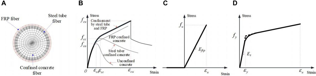
Figure 2. Stress-strain curves of constituent materials for FRP-confined CFST member. (A) Fiber section of FRP-confined CFST. (B) Stress versus strain relationship of concrete confinement by steel tube and FRP. (C) Stress versus strain relationship of FRP. (D) tress versus strain relationship of steel.
In order to verify the rationality of using the above materials to simulate the FRP confined CFST structure, these material models were used to simulate the axial compression test of the FRP confined CFST column conducted by Lu et al. (Lu et al., 2014), as shown in Figure 3. Four experimental cases were calculated and analyzed, including two short columns of CFRP-confined CFST and two short columns of GFRP-confined CFST. The size of these specimens is 128 mm in cross section diameter, 400 m in column height, 4 mm in steel tube wall thickness. The FRP wrap direction is circumferential, with layers of either 2 or 3 layers. The cube strength of the concrete cubes is 44.9 MPa, the yield strength of the steel is 248 MPa, the strength of CFRP and CFRP are 3550 MPa and 2930 MPa respectively, and the elastic modulus are 250 GPa and 109 GPa respectively. For more details of tests, see reference (Lu et al., 2014). The nonlinear fiber beam-column element model is established, as shown in Figures 3B,C. The axial force-displacement curve predicted by the above model is shown in Figure 4. The first stage is the elastic stage, where axial deformation changes linearly with load, and stiffness is relatively high. When the steel tube yielded, stiffness gradually decreases, it enters the plastic stage, the axial load of the specimens increased in an approximately linear way until the rupture of the FRP in the mid-height region happened. Table 1 summarizes the numerical predictions and the experimental data of the axial forces and displacements corresponding the yielding and failure stages as well as the ratios of experimental results to the numerical predictions and failure mode for all axial Compression test cases mentioned in Figure 4. As can be seen from Figures 4A–D and Table 1, the numerical results are quite consistent with the experimental results, which indicates that the model can predict the compressive capacity of the FRP-confined CFST column under axial compressive load, and reasonably reflects the confinement effects of steel tube and FRP on concrete. The above results demonstrate the reasonableness of the confined concrete material model and steel material model used in the study.
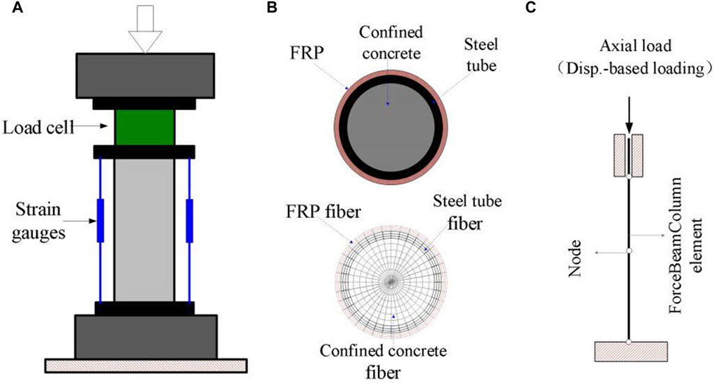
Figure 3. Experimental Setup for Axial Compression Test and Fiber Beam Element Model of FRP-confined CFST member (Lu, 2014). (A) Test Setup (Lu et al., 2014). (B) Fiber section of FRP- confined CFST. (C) FE model.
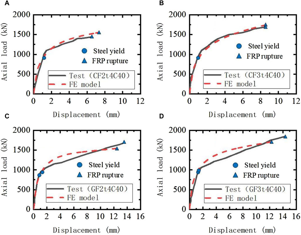
Figure 4. Comparison of axial force-displacement curves between axial compression test and analytical model.
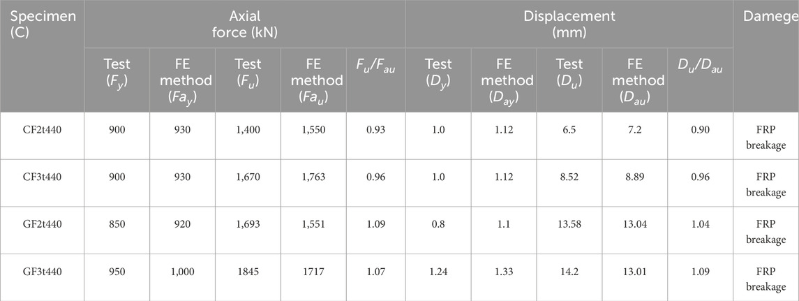
Table 1. Comparisons between the axial Compression experimental data and the numerically-predicted results.
In OpenSees, two different types of nonlinear beam-column elements can be used, namely, displacement-based beam-column elements and force-based beam-column element. Previous research (Kang et al., 2021) has shown that using displacement-based beam-column elements to simulate concrete structures may overestimate the bearing capacity of the structure. Therefore, in this study, force-based beam-column element will be used to establish the model. To further validate whether the model built according to the proposed method can reasonably predict the behavior of FRP-confined CFST member, the Static test of flexural behavior of FRP-confined CFST members conducted by Huang Junfei et al. (Huang, 2016) was adopted, as shown in Figure 5A. A total of 12 test cases were simulated in this paper. The size of these specimens is 1000 m in column height, the net span is 900 mm, and the FRP wrapping method is longitudinal wrapping Parameter variations include: section radius (three kinds: 65.5 mm (YA1 and YA2),57 mm (YB3),44 mm (YC1)), tube wall thickness (three kinds: 1 mm for YA1 and YC1, 1.5 mm for YA2, 2 mm for YB3), and the number of FRC wrapping layers (four kinds: 0 layer, 1 layer, 2 layer, 3 layer). The cube strength of the concrete cubes is 49.1 MPa, the yield strength of the steel with a wall thickness of 1.0 mm, 2 mm and 3.5 mm is 436 MPa, 451 and 446 MPa, respectively. Further details can be found in Junfei Huang et al. (Huang, 2016). Using the simulation method proposed above, the finite element model of FRP confined CFST column was established, as shown in Figure 5B.
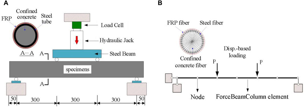
Figure 5. Flexural Test of FRP-confined CFST member Members Conducted by Huang (2016). (A) Flexural Test setup Huang (2016). (B) FE model.
The moment-midspan displacement curves predicted by the above model are shown in Figure 6, where the moment was calculated according to formula (3). Table 2 summarizes the numerical predictions and the experimental data of the moment and displacements at maximum load capacity as well as the ratios of experimental results to the numerical predictions and failure mode for all Flexural Compression test cases mentioned in Figure 6. From Figures 6A–L and Table 2, it can be observed that the numerical results of all 12 specimens, whether CFST or FRP-confined CFST column, are in good agreement with the test results. Indicating that the tensile-only linear elastic uniaxial material model (ElasticPPGap in OpenSees) effectively simulate the contribution of FRP material to the lateral resistance of the member. Also, the sudden drops in the moment were observed for the experimentally-measured moment displacement curves, as shown in Figures 6B,D,F,H,J, K, E. Such changes in the curve were attributed to the fact that the rupture of the FRP resulted in the decrease of the lateral resistance of the member. More importantly, the sudden drops can be predicted well by the developed FE model. It means that the proposed analysis method is able to accurately capture the cracking response of member under lateral loading. This demonstrates that the model can accurately predict the lateral resistance of FRP-confined CFST structures under lateral loads. These results indicate the applicability of the proposed modeling method.
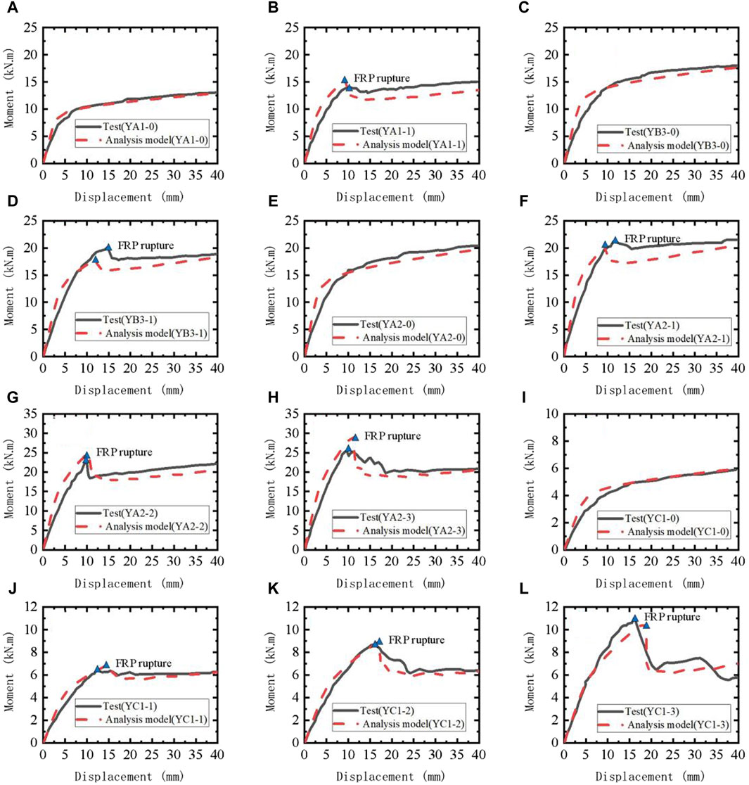
Figure 6. Comparison of Moment-Midspan Displacement Curves between Experimental date and Predicted by Analytical Model Huang (2016).
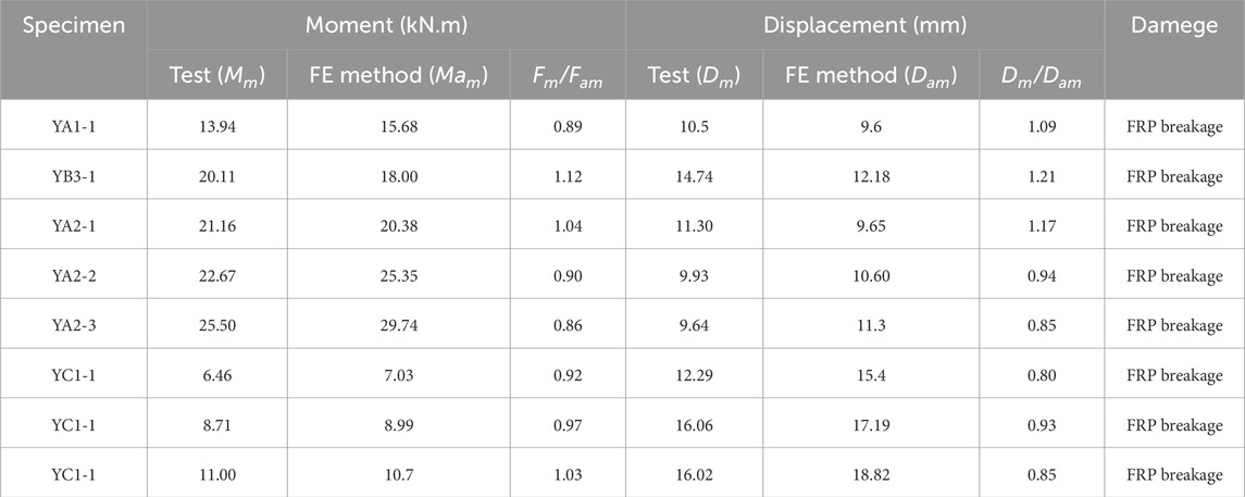
Table 2. Comparisons between the Flexural experimental data and the numerically-predicted results.
Where M is the moment at the pure bending section of the specimen, calculated according to Equation 3; P is the sum of vertical forces; L is the net span length of the specimen.
4 Efficient model of FRP-confined CFST member under impact loading
The efficient FE model of FRP-confined CFST member under impact loading can be developed by coupling the SDOF impactor and the marcoelement-based contact model with the nonlinear fiber-based beam-column element model of FRP-confined CFST member discussed above. As shown in Figure 7B. In the model, the mass-spring model representing the impactor is coupled with the nonlinear fiber-based beam-column element mode using a the marcoelement-based contact model at the impact point (A).
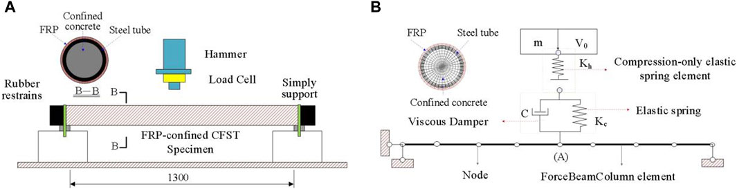
Figure 7. Drop weight impact test of FRP-confined CFST members Conducted by (Alam et al., 2017). (A) Test setup (Alam et al., 2017). (B) Proposed analysis model.
Previous studies have shown (Guohao, 1989; Ngo et al., 2007) that the strain rate of structures subjected to low-velocity impact loading ranges from 10–1 to 102 s-1. Therefore, different from static or seismic analysis, the strain rate effect of concrete and steel should be considered in impact simulation. Similar to literature (Fujikake et al., 2009), the strain rate effect of steel materials in this study was considered by the following formula (Equation 4) provided by the Japanese Society of Civil Engineers (JSCE) (Japan Society of Civil Engineers, 1993).
where
For concrete in compression, the dynamic increase factor (
Theoretically, the strain-rate effects of concrete under tension could also be included. However, numerical results indicate that the strain-rate effects of concrete under tension is not obvious when using nonlinear beam-column elements based on fiber cross-sections in low-velocity impact. The strain-rate effect of concrete in tension can be omitted for simplification, which will be demonstrated in the following validation section. Additionally, considering the strain-rate effect of concrete in tension may suffer from the difficulty of calculation convergence. Therefore, the strain-rate effects of concrete under tension are neglected in this study.
If the aforementioned modeling strategy were directly implemented in existing finite element programs, it would require accessing the source code and involve tedious code modifications, greatly limiting the application of the proposed method. Therefore, a simple approach is adopted in this study to approximate the effect of strain-rate on impact response. The relationship between strain rate and dynamic amplification factor (DIF) calculated by the above two formulas. It is observed that under low-velocity impact (10–1 to 102 s-1), the range of variation for DIFs is 1.162–1.28, and for DIFc is 1.069–1.17. Hence, it is noted that both materials exhibit relatively small fluctuations in dynamic increase factors under low-velocity impact. Therefore, for simplicity, the dynamic increase factors for steel and concrete in this study are set as DIFs = 1.22 and DIFc = 1.12, respectively, to estimate their strain-rate effects, resulting in the calculation error of material strength within 5%.
In order to verify the rationality of the approximate method for considering the strain rate of steel and concrete materials, the modeling method proposed in this paper is adopted to establish impact analysis models for two concrete-filled steel tube specimens from reference (Alam et al., 2017), As shown in Figure 7, these two conditions are identical except for the initial impact velocities of the hammer (V1 = 5 m/s, V2 = 3.28 m/s). The cross-section radius of the specimens is 114.3 mm, the steel tube wall thickness is 4.5 mm, and the boundary conditions are simply supported at both ends with a clear distance of 1300 mm, The mass of the hammer is 592 kg, the yield strength of the steel used in the components is 366 MPa, and the uniaxial compressive strength of the concrete is 29.7 MPa. Kh = 2 × 10⁹ N/m,
where
The numerical results of the impact-induced results (i.e., impact force, and midspan displacement) are shown in Figure 8. It can be seen from the figure that the calculated results from the model are in good agreement with the experimental results, indicating that the model, which approximately considers the strain rate of steel and concrete materials, can reasonably predict the dynamic impact response of CFST members.
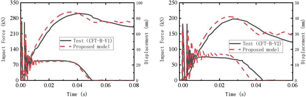
Figure 8. Comparison of dynamic response results between test date and predicted by analytical model.
Due to experimental constraints, earlier studies have traditionally believed that the strength of FRP materials remains relatively stable under different strain rates, with insignificant strain rate effects (Harding and Welsh, 1983). While, experimental studies have shown that FRP is a strain rate-sensitive material, with a significant increase in strength at higher strain rates compared to static conditions (Chen et al., 2002) (Ochola et al., 2004). However, as FRP is a novel material, the study of strain rate effect is still in a preliminary stage, So far, there is few formula for calculating the strain rate effects of FRP materials. Therefore, this study adopts a parameter discussion approach to explore the values of dynamic amplification factors for FRP materials under low-velocity impact.
Similarly, using the modeling approach described above, analytical models were established to simulate the drop hammer impact tests conducted by Alam et al. (2017) on FRP-confined CFST specimens. Two test conditions (CCFT-LL-V1 and CCFT-LLL-V1) were utilized to investigate the magnitude of the dynamic amplification factors for FRP materials. The experimental setup and dimensions of the specimens were consistent with the impact test of CFST above, as shown in Figure 7A. The difference is that the FRP- confined CFST specimens were wrapped with different layers of FRP material (2 layers of longitudinal CFRP for CCFT-LL-V1 and 3 layers of longitudinal CFRP for CCFT-LLL-V1).
In order to evaluate the effect of dynamic amplification factors of FRP material on the lateral dynamic response of the FRP-confined CFST member under low-velocity impact, three different factors (1, 1.2, 1.5) were investigated for their effects on the midspan displacement time history of the members. Figures 9A,B present the midspan displacement time history obtained from numerical simulations and experimental data. The results indicate that when the DIF parameter is set to 1, both the peak displacement and residual displacement of the midspan are significantly higher than the experimental values, suggesting an underestimation of the lateral impact resistance of the FRP-confined CFST components when the strain rate effect of FRP is not considered. While the DIF parameter is set to 1.5, the peak and residual displacements of the midspan for both conditions are in good agreement with the experimental results. This indicates that using a DIF parameter of 1.5 can reasonably assess the effect of FRP material strain rate under low-velocity impact. Therefore, in this study, to approximate the strain rate effect of FRP on impact response, the DIF parameter is set to 1.5.
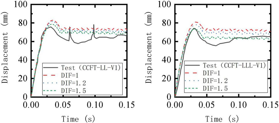
Figure 9. The Effect of FRP Strain Rate Sensitivity on the Impact Displacement Response.
5 Validation of the proposed model
A total of 9 FRP-confined CFST members reported in literature (Alam et al., 2017) were used to verify the proposed efficient analysis model. M. I. et al. (Alam et al., 2017) conducted impact tests on FRP-confined CFST members with simply supported ends using drop hammer test equipment, as shown in Figure 7. In the experiment, the influence of FRP type, wrapping method, and number of wrapping layers on the lateral impact response of the FRP-confined CFST members were studied. The CFRP and GFRP used in the experiments had elastic modulu of 75 GPa and 23 GPa, with ultimate tensile strengths of 987 MPa and 508 MPa, respectively. Further details of the experiment can be found in reference (Alam et al., 2017). Similarly, model-related parameters were determined based on the aforementioned method (e.g., Kc = 3 × 10⁸ N/m and C = 64,000).
Based on the above drop hammer impact test, a nonlinear beam-column efficient analysis model for FRP-confined CFST members is established, as shown in Figure 7B. The results obtained from the numerical model (e.g., mid-span impact point displacement and impact force), along with the corresponding experimental data, are presented in Figure 10 and Table 3. Table 3 summarizes the peak impact forces, the average force at the plateau stage, peak lateral displacement and residual displacements as well as the ratios of experimental results to the numerical predictions and failure mode for all impact test cases mentioned above. It can be observed from the figure that the proposed numerical model can effectively predict the impact dynamic response of FRP-confined CFST members across all series tested in the experiments, indicating that the proposed simulation method can accurately predict the lateral impact resistance of FRP-confined CFST members.
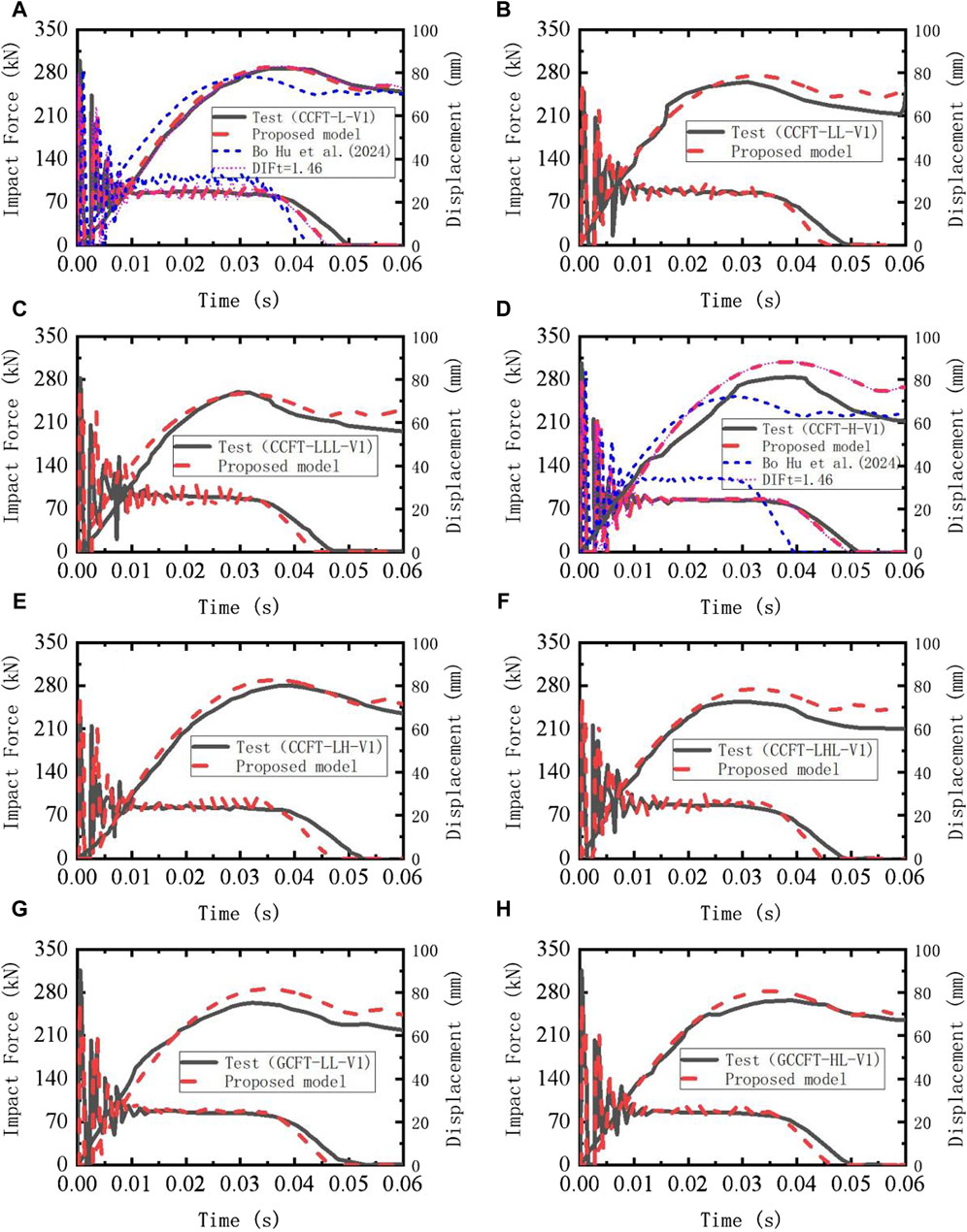
Figure 10. Comparison of Dynamic Response Results between Impact Test and Predictions by proposec Analytical Models (Alam et al., 2017).
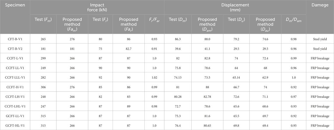
Table 3. Comparisons between the Drop Weight Impact experimental data and the numerically-predicted results.
In addition, the equation proposed by Xiao et al. (Xiao et al., 2010) was employed to examine the influence of the strain-rate effect of concrete in tension, where a relatively high strain-rate (102) was assumed for the conservative evaluation. As shown in Figures 10A,D, the numerical results with the strain-rate effect of concrete in tension are almost consistent with those without the strain-rate effect. This is mainly attributed to the fact that although the tensile strength of the concrete can be greatly increased (by about 50%) due to consider the strain-rate effect, it is still very small in comparison with the tensile strength of the steel tube and FRP. Accordingly, it has little contribution to the tensile resistance of FRP confined CFST structure on the tension side. Hence, as mentioned above, the strain-rate effect of concrete in tension was omitted for the following simulations in this study.
Bo Hu (Hu and Wang, 2024) established the detailed FE model of the two typical impact tests (specimens CCFT-L-V1 and CCFT-H-V1) with the software LS-DYNA. In the detailed FE model, the concrete material model MAT_CONCRETE _DAMAGE_REL3 was used to simulate the concrete, and the elastic-plastic material model MAT_PIECEWISE_LINEAR_PLASTICITY was adopted to model the steel tube. The perfect bond was assumed between the concrete and the steel tube. The *MAT_ENHANCED_COMPOSITE_DAMAGE material model was selected to simulate the behavior of the FRP under dynamic loading. For multi-layered FRP, the *PART_COMPOSITE keyword was employed to set the material properties, thickness, and orientation of each layer. The interfacial behavior between the FRP and the steel tube was modelled using the*CONTACT_TIED_SURFACE_TO_SURFACE contact algorithm. The contact algorithm is constraint-based. Additional information about the detailed FE modeling can be found in (Hu and Wang, 2024). The numerical results obtained from the detailed FE model are presented in Figure 10 for comparison. Based on the results of the two tests, the accuracy of the proposed method is comparable to that of the detailed FE simulation. However, Based on the steady-state value of the impact force-time curve and the peak displacement value, the proposed method can better predict the lateral capacity under low-velocity impacts.
On the other hand, the proposed method significantly improves computational efficiency, at least by two orders of magnitude, and reduces the computational resources (computing power and storage space) required compared to using detailed finite element models. Compared with the analysis model proposed by Fujikake et al. (Wang and Morgenthal, 2017), the proposed method can obtain the entire deformation and internal forces along the length of the beam and can also be easily applied to practical analyses of vehicle collisions and ship impacts.
Compared to low-velocity impacts, the local damages around the contact-impact zone are much more severe during high-velocity impacts. Due to the differences between low-velocity and high-velocity impacts, further study is needed to expand the application of the proposed modeling method in high-velocity impact analysis.
6 Conclusion
This paper proposed an efficient analysis model to predict the performance for FRP-confined CFST members under impact loads based on nonlinear beam elements and extensively validated it utilizing existing experimental data. The main conclusions are as follows:
(1) The selected confined concrete model in this paper is validated by existing experiments, demonstrating its ability to reasonably describe the mechanical behavior of concrete under the composite confinement effect of FRP and steel tubes. The tensile-Only material model can accurately predict the contribution of longitudinally wrapped FRP to the resistance of the member.
(2) Under low-velocity impact, neglecting the strain rate effect of FRP would underestimate the lateral impact resistance of the component. When the dynamic amplification factor DIF is set to 1.5, it can better consider the contribution of FRP material strain rate effect to the lateral resistance of the member.
(3) Combined with the macro-element model of the impact object and the nonlinear fiber beam and column element model of FRP-confined CFST member, as well as approximating the strain rate effect appropriately, an efficient analysis model for FRP-confined concrete members under impact loading is constructed, It can reasonably predict the dynamic response of FRP-confined CFST member under lateral impact. Through verification with existing impact tests, it is proved that the proposed method is reliable in evaluating the impact force and the deflection caused by the impact of FRP confined CFST member.
(4) Additionally, the proposed method is significantly more efficient in terms of computational efficiency compared to detailed finite element models with 3-D solid elements. The proposed modeling approach can be easily applied to any finite element software containing fiber-based nonlinear beam-column elements and discrete macroscopic elements without the need for coding. Based on the research in this paper, the proposed method can be applied to establish full structural models (such as the full-bridge model) and conduct extensive simulations of impact collisions of FRP-confined CFST members in full structural models. This can be utilized to analyze the continuous collapse resistance and reliability of FRP-confined CFST structures under various collision scenarios.
Data availability statement
The original contributions presented in the study are included in the article/supplementary material, further inquiries can be directed to the corresponding authors.
Author contributions
JT: Funding acquisition, Writing–original draft. BL: Funding acquisition, Writing–review and editing, Writing–original draft. LK: Funding acquisition, Writing–review and editing. WF: Writing–review and editing. DZ: Writing–review and editing. TW: Writing–review and editing. LH: Writing–review and editing. JX: Writing–review and editing.
Funding
The author(s) declare that financial support was received for the research, authorship, and/or publication of this article. This research is supported by the Guangxi Provincial Natural Science Foundation of China (Grant Number:2021GXNSFBA075034), the Guangxi Provincial Natural Science Foundation of China (Grant Number:2024GXNSFBA010439), the Key Science and Technology Project List for the Transportation Industry of Guangxi Province (Grant Number: QD2022-174-066) , the Key Science and Technology Project List for the Transportation Industry of Guangxi Province (Grant Number: QD2022-174-022).
Conflict of interest
Authors JT, LH, and JX were employed by Guangxi Shangheng Expressway Co., Ltd.
Authors BL and LK were employed by Hualan Design & Consulting Group.
The remaining authors declare that the research was conducted in the absence of any commercial or financial relationships that could be construed as a potential conflict of interest.
Publisher’s note
All claims expressed in this article are solely those of the authors and do not necessarily represent those of their affiliated organizations, or those of the publisher, the editors and the reviewers. Any product that may be evaluated in this article, or claim that may be made by its manufacturer, is not guaranteed or endorsed by the publisher.
References
Alam, M. I., Fawzia, S., Zhao, X. L., Remennikov, A. M., Bambach, M., and Elchalakani, M. (2017). Performance and dynamic behaviour of FRP strengthened CFST members subjected to lateral impact. Eng. Struct. 147 (15), 160–176. doi:10.1016/j.engstruct.2017.05.052
Chen, C., and Yinghua, ZHAO. Simulation analysis of impact resistance of FRP-concrete-filled steel tubes. Chin. J. Vib. Shock, 2013, 32(19):197–201. doi:10.13465/j.cnki.jvs.2013.19.033
Chen, C., Zhao, Y. H., and Li, J. (2015). Experimental investigation on the impact performance of concrete-filled FRP steel tubes. J. Eng. Mech. 141. doi:10.1061/(asce)em.1943-7889.0000833
Chen, C., Zhao, Y. H., Zhu, C. Y., and Wei, L. (2011). Study on the impact response of concrete filled FRP-steel tube structures. Adv. Mater. Res. 368-373, 549–552. doi:10.4028/www.scientific.net/amr.368-373.549
Chen, W., Lu, F., and Cheng, M. Tension and compression tests of two polymers under quasi-static and dynamic loading[J]. Polym. Test., 2002, 21(2):113–121. doi:10.1016/s0142-9418(01)00055-1
Chunyang, Z., Yinghua, Z., Yue, Y., Ke, W., and Li, S.(2018). Seismic behavior of thin-walled concrete-filled steel tubes reinforced by local buckling FRP. Chin. J. Comput. Mech. 035(005), 552–559. doi:10.7511/jslx20170507001
Debo, Z. (2017). Study on response characteristics and design method of reinforced concrete beams under impact loads. China: Hunan University.
Fan, W., and Yuan, W. C. (2014). Numerical simulation and analytical modeling of pile-supported structures subjected to ship collisions including soil–structure interaction. Ocean. Eng. 91, 11–27. doi:10.1016/j.oceaneng.2014.08.011
Fang, J. (2017) “Review of research and test on properties of FRP confined concrete-filled steel tube composite columns [C]. China,” in Proceedings of the 17th national symposium on modern structural engineering, 983–988.
Fujikake, K., Li, B., and Soeun, S. (2009). Impact response of reinforced concrete beam and its analytical evaluation. J. Struct. Eng. 135 (8), 938–950. doi:10.1061/(asce)st.1943-541x.0000039
Guohao, Li (1989). Antiknock dynamics of engineering structures. Shanghai: Shanghai Science and Technology Press.
Harding, J., and Welsh, L. M. A tensile testing technique for fibre-reinforced composites at impact rates of strain[J]. J. Mater. Sci., 1983, 18(6):1810–1826. doi:10.1007/bf00542078
Hu, Bo, and Wang, H.-Bo (2024). Performance evaluation and FRP strengthening of concrete-filled steel tubular columns subjected to vehicle impact. Adv. Struct. Eng. 27 (8), 1377–1396. doi:10.1177/13694332241252281
Hu, Y. M., Yu, T., and Teng, J. G. (2011). FRP-confined circular concrete-filled thin steel tubes under axial compression. J. Compos. Constr. 15 (5), 850–860. doi:10.1061/(asce)cc.1943-5614.0000217
Huang, J. (2016). Research on flexural performance of Stainless steel tube concrete reinforced by CFRP. China: Huaqiao University.
Japan Society of Civil Engineers. Impact behavior and design of structures. Structural engineering series 6, JSCE, Tokyo, 1993
Kang, L., Fan, W., Liu, B., and Liu, Y. (2021). Numerically efficient analysis of concrete-filled steel tubular columns under lateral impact loading. J. Constr. Steel Res. 179, 106564. doi:10.1016/j.jcsr.2021.106564
Li, Q. M., and Meng, H. (2003). About the dynamic strength enhancement of concrete-like material in a Split Hopkinson pressure bar test. Int. J. Solid Struct. 40 (2), 343–360. doi:10.1016/S0020-7683(02)00526-7
Liu, L. (2009). Study on Basic Mechanical Properties of FRP and concrete-filled steel tube composite columns. China: Wuhan University.
Lu, Y. Y., Li, N., and Li, S. (2014). Behavior of FRP-confined concrete-filled steel tube columns. Polym. Bull. 6, 1333–1349. doi:10.3390/polym6051333
Ngo, T., Mendis, P., Gupta, A., and J. Ramsay, (2007). Blast loading and blast effects on structures – an overview. Electron. J. Struct. Eng. 7, 76–91. doi:10.56748/ejse.671
Ochola, R. O., Marcus, K., Nurick, G. N., and Franz, T. (2004). Mechanical behaviour of glass and carbon fibre reinforced composites at varying strain rates. Compos. Struct. 63 (3-4), 455–467. doi:10.1016/s0263-8223(03)00194-6
Qin, P. (2016). Research on seismic performance of concrete-filled steel tube columns confined by CFRP. China: Hunan University.
Qingli, W., Jia, Li, and Weijuan, ZHAO (2013). Analysis of Bearing capacity of square section carbon fiber reinforced polymer-concrete filled steel tube axial compression column. Chin. J. Build. Struct. 34 (S1), 274–280. doi:10.14006/j.jzjgxb.2013.s1.041
Saini, D., and Shafei, B. (2018). Investigation of concrete-filled steel tube beams strengthened with CFRP against impact loads. Compos. Struct. 208, 744–757. doi:10.1016/j.compstruct.2018.09.057
Shakir, A. S., Guan, Z. W., and Jones, S. W. (2016). Lateral impact response of the concrete filled steel tube columns with and without CFRP strengthening. Eng. Struct. 116, 148–162. doi:10.1016/j.engstruct.2016.02.047
Teng, J. G., Hu, Y. M., and Yu, T. (2013). Stress–strain model for concrete in FRP-confined steel tubular columns. Eng. Struct. 49 (Apr), 156–167. doi:10.1016/j.engstruct.2012.11.001
Wang, Q., Liu, K., and Zhang, M. (2022). Numerical studies on the performance of the circular fibre reinforced plastics-concrete filled steel tubes stub column under axial compression. J. Reinf. Plastics Compos. 41 (9-10), 383–398. doi:10.1177/07316844211051707
Wang, Q., Ye, M. A. O., and Lin, Z. (2008). Research on flexural behavior of circular CFRP-concrete-filled steel tube members. China: Journal of Civil Engineering, 30–38.
Wang, W., and Morgenthal, G. (2017). Dynamic analyses of square RC pier column subjected to barge impact using efficient models. Eng. Struct. 151, 20–32. doi:10.1016/j.engstruct.2017.08.003
Xiao, S., Li, H., and Monteiro, P. J. M. (2010). Influence of strain rates and load histories on the tensile damage behaviour of concrete. Mag. Concr. Res. 62 (12), 887–894. doi:10.1680/macr.2010.62.12.887
Xiao, Y. (2001). Applications of FRP composites in concrete columns. Adv. Struct. Eng. 7 (4), 335–343. doi:10.1260/1369433041653552
Ye, L., and Peng, F. (2006). Application and development of FRP in engineering structures. J. Civ. Eng. (03), 24–36. doi:10.3321/j.issn:1000-131X.2006.03.004
Yong, Xu, Hongyuan, T., Junlong, C., Liu, Ye, and Liu, R. (2021). Numerical analysis of CFRP-confined concrete-filled stainless steel tubular stub columns under axial compression. J. Build. Eng. 37, 102130. doi:10.1016/j.jobe.2020.102130
Yu, F., and Wu, P. (2010). Study on stress-strain relationship of FRP-confined concrete filled steel tubes. Adv. Mater. Res. 163-167, 3826–3829. doi:10.4028/www.scientific.net/amr.163-167.3826
Zhang, Y., Wei, Y., Bai, J., and Zhang, Y. (2019). Stress-strain model of an FRP-confined concrete filled steel tube under axial compression. Thin-Walled Struct. 142, 149–159. doi:10.1016/j.tws.2019.05.009
Keywords: fiber-reinforced polymer, concrete filled steel tube, FRP confined CFST structures, efficicent modeling, low-velocity impact
Citation: Tang J, Liu B, Kang L, Fan W, Zhao D, Wang T, He L and Xie J (2024) Numerically efficient analysis of FRP confined CFST members under lateral low-velocity impact loading. Front. Mater. 11:1435059. doi: 10.3389/fmats.2024.1435059
Received: 19 May 2024; Accepted: 26 July 2024;
Published: 21 August 2024.
Edited by:
Daniel Cardoso, Pontifical Catholic University of Rio de Janeiro, BrazilCopyright © 2024 Tang, Liu, Kang, Fan, Zhao, Wang, He and Xie. This is an open-access article distributed under the terms of the Creative Commons Attribution License (CC BY). The use, distribution or reproduction in other forums is permitted, provided the original author(s) and the copyright owner(s) are credited and that the original publication in this journal is cited, in accordance with accepted academic practice. No use, distribution or reproduction is permitted which does not comply with these terms.
*Correspondence: Bin Liu, NzYzNDMyODU4QHFxLmNvbQ==; Lijing Kang, MjgwOTAxNjk4QHFxLmNvbQ==