 Nilesh Agarwal1Aditya Rangamani2Kathan Bhavsar1Shreyash Santosh Virnodkar1Aldrin Antonio Agostinho Fernandes1
 Utkarsh Chadha3
 Divyansh Srivastava4*
 Albert E. Patterson5,6Vezhavendhan Rajasekharan1
- 1School of Mechanical Engineering (SMEC), Vellore Institute of Technology (VIT), Vellore, Tamil Nadu, India
- 2Department of Mechanical Engineering, Indian Institute of Technology, Tirupati, India
- 3Department of Materials Science and Engineering, Faculty of Applied Sciences and Engineering, School of Graduate Studies, University of Toronto, Toronto, ON, Canada
- 4Technische Universitat Darmstadt, Darmstadt, Germany
- 5Faculty of Manufacturing and Mechanical Engineering Technology, Department of Engineering Technology and Industrial Distribution, Texas A&M University, College Station, TX, United States
- 6J. Mike Walker ’66 Department of Mechanical Engineering, Texas A&M University, College Station, TX, United States
Carbon-carbon composites are advanced materials known for their high strength, high-temperature stability, and superior thermal conductivity. Mechanical properties such as tensile strength, flexural strength, and compressive strength are examined, as well as thermal properties like the coefficient of thermal expansion and thermal conductivity, to understand the characteristics of the composite. Carbon-carbon composites are ideal for the aerospace industry’s need for lightweight and high-performance materials. Tribological and surface properties are relevant to this discussion, given the use case of carbon-carbon composites in extreme conditions, the effect of exposing the composite to different fluids and the change in friction and wear properties. Coatings can protect the composite from environmental factors such as UV radiation, oxidation, and erosion. Self-healing composites that can repair themselves can increase the lifespan of structures while reducing maintenance costs. These have been used in aerospace applications such as airplane braking systems, rocket nozzles, and re-entry vehicle heat shields. Furthermore, researchers have recently addressed the problem of finishing and drilling without delamination and loss of properties, and this study looks into unconventional methods that can be adopted for the same. This study aims to provide an overview of the current state of carbon-carbon composite materials and their applications.
Introduction
A composite material is a mixture or combination of two or more elements that display unique structural properties superior to those of the component parts used alone. These are two or more chemically different constituents combined macroscopically to yield a useful material. The property of the final product is significantly different from that of its constituents (Scarponi, 2016).
A composite material can be in its natural or manufactured form, with the components interacting rather than dissolving or blending fully into the composite. A form of synthetic, pure carbon material called carbon composite is constructed of carbon fibers reinforced by a carbon matrix. These are classified as advanced composite materials, including carbon-carbon composites. (C/C) (Scarponi, 2016).
Composites of carbon fibers reinforced by a carbon matrix are called C/C materials. These 1970s-era composites improved the opposition toward thermal blow by withstanding wide temperature variation and compacting the thermal expansion caused by thermal stress and strain changes. These possess inertness to chemicals alongside suitable biocompatibility, low density, and higher strength and stiffness at high temperatures.
It also showcases improved form stability and high-temperature wear characteristics. A sustenance behavior is guaranteed toward the dynamic shear fracture and pseudo-plastic (Scarponi, 2016). These characteristics promise its application in various fields, including the aerospace, sporting goods, and medical sectors. Carbon and graphite exhibit significant ablation resistance because of their high sublimation heat and low thermal expansion.
As seen in Figure 1, depending on the raw material used (yarns, tapes, fabrics, knitted and braided preforms), composite materials can take on a range of shapes, ranging from one-dimensional to n-dimensional. The microstructures and properties of the composite group C/C can be tailored for a variety of purposes. Owing to the thermal properties of the C/C composite family, that is the increased rate of conductivity and nominal expansion, makes them highly resistive to thermal stresses (Sheehan et al., 1994).
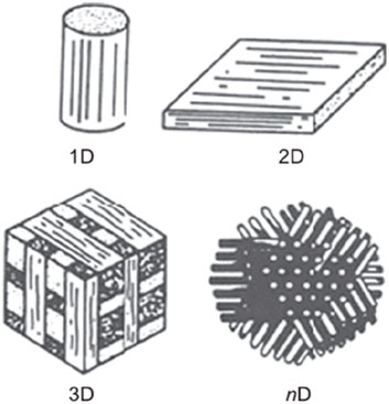
Figure 1. Different forms of carbon fibre and carbon matrix composites (Scarponi, 2016). Copyright 2016 by Elsevier Ltd.
Properties such as exceptional high-temperature mechanical characteristics and low density are the added advantages of working on structural applications qualifying C/C composites as a favoured and eminent choice for the aerospace industry (Sheehan et al., 1994). A composite with a brittle matrix might have high strength and stiffness enthralling outstanding damage endurance and good thermal shock behaviour (Sheehan et al., 1994).
These Synthetic fibrous composites are a unique type of thermo-structural material with many potential uses, including the construction of engine parts and aircraft assemblies, as well as the fusion of atomic nuclei at high temperatures. These materials have excellent high-temperature mechanical properties and are frequently used in the aviation and spaceflight industries. Research is ongoing to reduce the cost of C/C composites in order to expand their applications (Simil et al., 2013).
Understanding C/C composites
C/C composites are highly sought after in aerospace engineering due to their excellent mechanical properties at high temperatures. These composites are made by adding carbon fibers to a carbon-based matrix, which combines the matrix’s strong thermal resistance with the fibers high specific mechanical characteristics. Other desirable characteristics of C/C composites include high specific stiffness and strength, retention of mechanical properties at extreme temperatures, biocompatibility, and chemical inertness. There are two main methods for producing C/C composites:
1. Chemical vapour deposition (CVD) utilising a hydrocarbon gas, and
2. Carbonization by pyrolysis of an organic matrix (both thermosetting and thermoplastic) (Rana and Fangueiro, 2016).
There are several factors to consider when selecting a matrix for a C/C composite. The impregnation choice and heat-treatment temperature (HTT) can significantly affect the fibre-matrix interactions and mechanical properties of the composite. The density of the matrix is also important, as the initial porosity of the preform plays a role in the coal-tar pitch densification of C/C composites (Park and Cho, 2000).
To date, in Carbon Matrix Composites, the interactions between the fibers and matrix (F/M) can be probed through two main approaches. These interfaces between the fibre and the matrix can be investigated by loading in two modes: opening mode or in shearing mode as depicted in Figure 2. Three factors contribute to the ascertainment of the interfacial shear stress of the Carbon Matrix Composites. This is the tensile behaviour, a developing and glaring hysteresis loop opening phenomenon prior to the stress fracture disclosing the particulars of microstructural defilement, and the gaps and voids evolving in the matrix separation from the first method, which uses micro/mini composites.
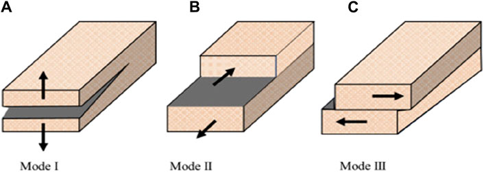
Figure 2. Three basic failure modes: (A) opening mode; (B) in-plane shear mode (C) out-of-plane mode (Huang et al., 2021) under CC BY 4.0.
In the second method, micro-indentation techniques are used, to cast the mechanical properties of the fibre/matrix confluence of a fibre-reinforced composite. By adopting these micro-indentation methodologies, that is the fibre push-out or push-in tests and measuring the extrinsic properties using the load-displacement curve, the F/M interfacial shear stress can be approximated in the second method. Both of these methods fundamentally take into account a shearing mode. In push-out tests, despite the challenges due to the low elastic modulus of carbon matrix and fragile fiber/matrix bonds, the challenges ranging from preparing the specimen, to changing of the results have been successfully overcome.
The yielding and slacking of the weak F/M bonds can result in an unanticipated protruding of jutted fibers being surfaced in the course of preparing the metallographic specimens owing to the lateral expansion of carbon fibre. It is possible to assess the allowance of roughness to the interfacial shear stress by doing push-out tests on these protruding fibers.
Push-back tests may be used to accurately determine this contribution. The specimens used for the tensile testing had fibre orientations of 90, 30, and 30 to the loading axis. Such fibre orientation has been demonstrated to encourage preferred F/M interface opening. This damage phase, which begins at extremely low loads, is connected to the spread of the pre-existing matrix fractures. Acoustic emission data can be used to assess opening strength (Scarponi, 2016).
C/C composites could be subjected to multi-factor coupling, where the environmental parameters and temperature could also hamper its ultimate performance. There have been various research works that summarize effects of various uncertainties which couple together in an environment that a composite is subjected to [71, 73]. There are limited research works that address multi-factor coupling related details and their mitigation strategies specifically for C/C composites. Table 1 explains the research works and suggests methods to mitigate and incorporate additions or changes in the process or materials for the C/C fibers in the cases of long-term, harsh environments and various other cases.
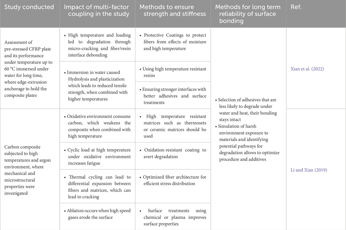
Table 1. Research work on C/C Composite under Multi-Factor Coupling and Mitigation Strategies for Long-Term Reliability.
Functionally graded materials
A functionally graded material (FGM) is an advanced composite material characterized by graded variations in the relative volumes of the constituent materials. For instance, a composite material that combines ceramic with metal. Due to its low thermal conductivity, ceramic provides high-temperature resistance, while metal provides strength and stiffness (Maalawi, 2018). A higher stiffness-to-weight ratio and superior fatigue characteristics are among the benefits of such fabrication for aerospace structures. Materials that are corrosion-resistant, anisotropic, and provide direct bending, axial, and rotation elastic coupling, as well as aeroelastic tailoring to improve structural design (Maalawi, 2018).
In aerospace applications, these functionally graded materials (FGMs) could be used on heat-resistant surfaces of spacecraft or aircraft engine parts due to their high-temperature resistance, thermal shock resistance, thermal fatigue resistance, and corrosion resistance. For example, the combustion chamber wall of a spacecraft engine must withstand high temperatures and thermal erosion above 2000K on one side, while the other side is cooled by liquid hydrogen at low temperatures. This requires the material to have excellent heat insulation properties on one side and high thermal conductivity on the other (Han, 2018).
The materials are functionally graded to withstand such significant temperature differences under mechanical load and thermal stress conditions, allowing for a long working life. A grading layout of such material is depicted in Figure 3. Other materials do not offer the same level of performance. Additionally, aircraft engines are high-precision components that require high hardness, wear resistance, corrosion resistance, and a low thermal expansion coefficient. Consequently, functionally graded materials can be worn and consumed quickly and have the same physical and chemical properties as traditional materials (Han, 2018).
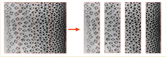
Figure 3. Material grading layout (Maalawi, 2018) CC BY 4.0.
Material characterization of C/C composites
One of the challenges in the estimation of the mechanical properties of C/C composites is their highly heterogeneous microstructure. It mainly consists of Carbon fibre reinforcements, Carbon matrix, voids, cracks and other defects. It will provide us with great insight if we can accurately decipher its mechanical properties [6].
Preparation methods tend to influence the properties of the composites manufactured by making amendments to general C/C composite manufacturing process, as shown in Figure 4. The methods deployed for reinforcing carbon fiber in the carbon matrix could be influenced by the application specific requirements where open-ended innovation is possible. And the parameters for processes could be manipulated or material could have various additions (Devi and Rao, 1993; Awasthi and Wood, 2008; Li et al., 2017; Yang et al., 2020).
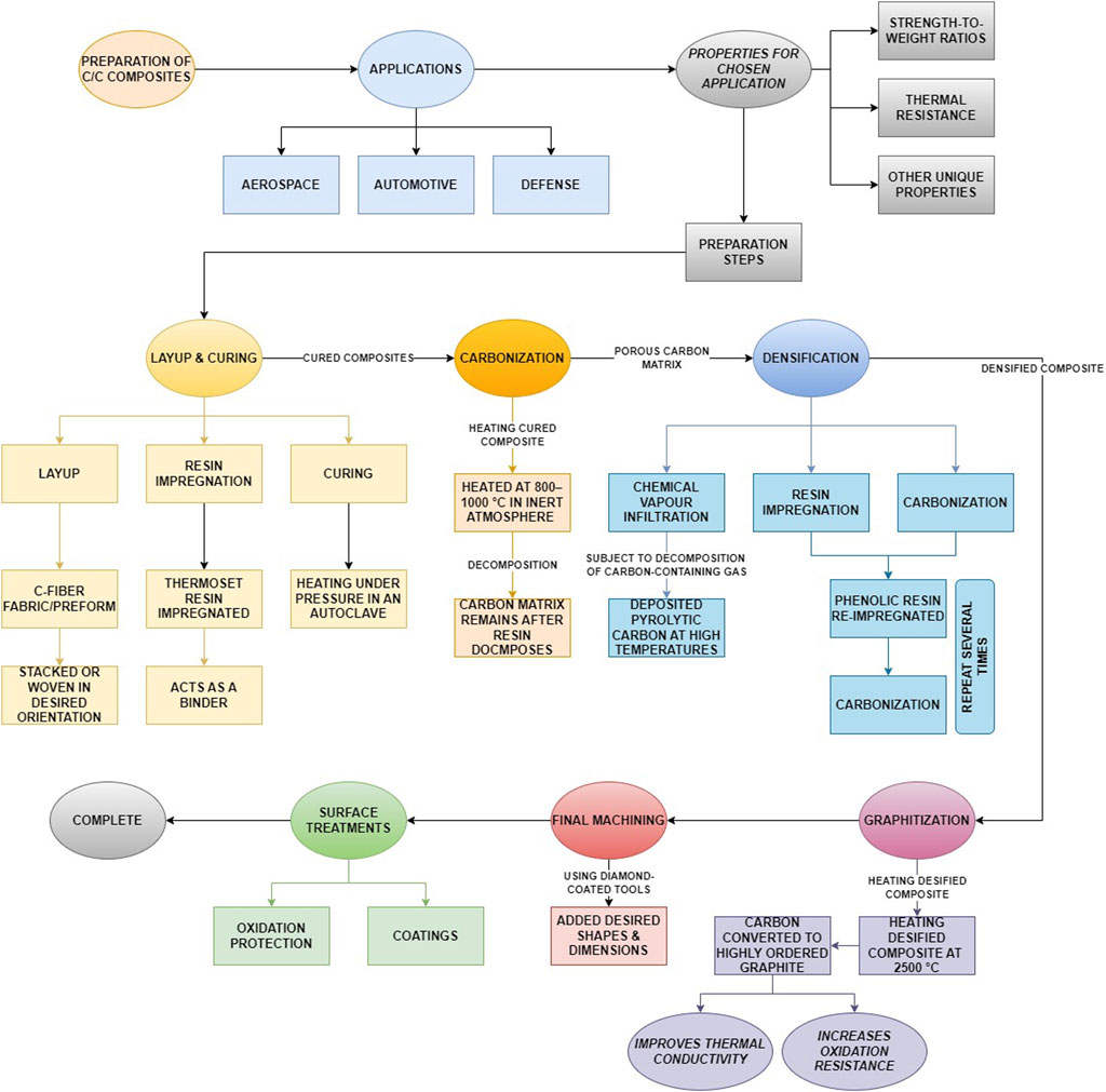
Figure 4. General preparation method for C/C composites.
Any changes in general would also influence the microstructure of the materials, while retaining the preferred properties for specific applications while optimizing the performance of the final composite. This can range from.
• Choice of resin,
• Impregnation methods,
• Carbonization temperatures,
• Densification Techniques
These specific parameters could be crucial for the final porosity, mechanical strength, and thermal properties of the C/C composite in short term and long term alongside their functional capabilities for specific applications, which has been expanded upon detailed in the later sections of this study.
Characterization of C/C composites involves testing of fatigue, mechanical, thermal and microscopic behavior. The research works in the field have deployed commonly used methods as explained below.
• Mechanical Testing: Tensile testing (Ultimate Tensile Strength and Modulus of Elasticity), Compressive Testing (Compressive strength), Flexural testing (Flexural strength and stiffness), and Shear Testing (Interlaminar shear strength).
• Fatigue Properties: Fatigue Testing (Fatigue for number of cycles or under varying stress).
• Thermal Properties: Thermogravimetric Analysis (Measuring weight change after decomposition), Differential Scanning Calorimetry (Heat flow assessment for transitions like melting or crystallization), Thermal Conductivity Testing (Hot disk or Laser flash for Conductivity).
• Microscopic Properties: Scanning Electron Microscopy (Surface Morphology), Transmission Electron Microscopy (Fine Structural and Phase Distribution Observations), X-Ray Diffraction (Crystallographic Structure Assessment), Raman Spectroscopy (Bonding Structure and Graphitic Content Analysis), Energy Dispersive Spectroscopy (Elemental Composition Assessment).
The yarn architecture of the composite is mainly determined by the arrangement of the fibre bundles. Typically, C/C composite yarn architecture is divided as follows: 3-D orthogonal, 4-D in plane, and 4-D diagonal composite. ‘n-D’ depicts the number of fibre bundle directions. We can use the yarn architecture to our advantage and modify the thermal and mechanical properties to our application.
A few manufacturing parameters such as yarn spacing, fibre volume fraction, and yarn size are instrumental in getting the required thermomechanical properties in the workpiece. Prior to the commencement of the manufacturing process, the manufacturing parameters as well as the constituents of the workpiece are selected. This can help in avoiding excessive testing expenses to obtain the desired material properties.
It also allows the end product to be optimised in terms of weight along with satisfying the basic properties. Considering a few properties of C/C composites such as Young’s Modulus, thermal conductivity, and electrical conductivity along the axis of the fibers are of the order of 900GPa, 1,000 Wm-1K−1 and 106 Sm-1. These are significantly greater than when measured along the transverse direction.
Typically, the properties of the composite are determined by the fibers (orientation, fibre volume fraction) and architecture (layup sequence), and thermal treatment. Heat treatment is usually applied when looking to improve on specific properties such as thermal diffusivity, electrical conductivity, thermal stability, and resistance to oxidation and corrosion.
Mechanical properties such as flexural strength, tensile strength, interlaminar shear strength, pore volume, compressive strength, bulk modulus, Young’s Modulus, and resistance to alternate loading can be improved by re-baking and impregnation. This has been confirmed by means of Non-Destructive Testing (NDT) methods such as acoustic emissions and thermal methods. The manufacturing process for composites is highly subjective. The process to be implemented is purely based on the thermal, mechanical, electrical and other desired properties [6].
For high temperature-resistant purposes, the solution lies in manufacturing high-density C/C composites. The manufacturing process required, however, is more time-consuming, sometimes even weeks with the manufacturing cost only increasing as a result. An example is using matrix precursors like petroleum pitches, which need to be processed using high pressure and high temperature, followed by impregnation and pyrolysis steps (Dekeyrel et al., 2013).
To create 3-D composites, several processes are used in sequence. One method starts with pre-densification, which fills the gaps in the fiber bundle and reduces large pores. This is followed by cycles of impregnation and pyrolysis under moderate pressure, carbonization, and graphitization, resulting in composites with a density greater than 1.8 g/cm3. This combination of processes also aids in reducing manufacturing costs and processing time (Dekeyrel et al., 2013).
A few notable processes employed for impregnation include: impregnation by carbonaceous sub-micronic powder slurry, a combination of impregnation/pyrolysis with carbonaceous impregnation, and film boiling chemical vapour filtration are significant in the pre-densification step. With the use of a slurry vacuum impregnation method (Figure 5), sub-micronic carbon black powder could be used to fill the pore volume present in the raw preforms (Dekeyrel et al., 2013).
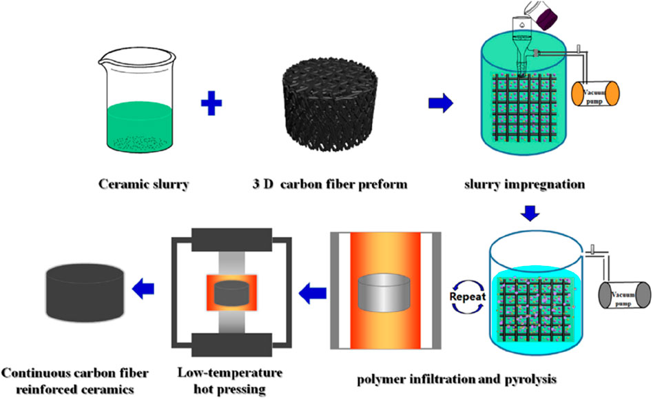
Figure 5. Fabrication of continuous carbon fiber ceramic composite via slurry impregnation (Zhang et al., 2019). Copyright 2019 by Elsevier Ltd.
Macias et al. (D Macías et al., 2019) were able to show the thermal conductivity and diffusivity of C/C composites experimentally in different directions: (1) along cross-plane and (2) along in-plane directions. The results of the study show that the values obtained for thermal conductivity and diffusivity for cross-plane orientation is about 20% of the values obtained for in-plane orientation. Further in the study, the thermal conductivity of cross-plane direction as a function of temperature was well-modeled by a theoretical model that considers both conductive and radiative effects on thermal conductivity. The number deduced from experiments and the theoretical model remains almost constant around 5.3 ± 0.4 W m−1K−1, within the temperature range from 300 K to 1700 K. Another important result established in the same study talks about the value of average spectral selectivity η = 48.5% for the workpiece used and this could be helpful in solar technology applications.
The limitation of C/C composites in aerospace and other applications continues to be oxidation during service. The two major approaches used to reduce oxidation rates are the application of more than one coating on the subject’s surface or incorporating an inhibitor during the composite’s manufacture. Protective coatings such as SiC or Si3N4 are favoured due to the relatively low coefficient of thermal expansion (CTE) mismatch and the organic formation of a thin film of SiO2 after oxidation. Halogens6 and borate-based substances are among the inhibitors. The latter is a continuous glass layer that is a diffusion barrier, whereas the former depends on chemical reactions (Xuetao et al., 2010).
Non-destructive testing
Post-machining and finishing of components, one needs to test the components to ensure that the parts lie within tolerance limits of desired properties. Testing is also used to make sure that the components have minimal manufacturing defects which can cause the loss of mechanical or thermal properties. There are mainly two types of testing that can be conducted on parts: destructive (DT) and non-destructive testing (NDT).
The surface level defects: cracks and porosity, can be noticed with the naked eye or by Non-Destructive Testing methods such as dye penetrant testing. To detect the sub-surface level defects, we can employ either DT or NDT methods. NDT methods are preferred to avoid damaging the component in the testing process. Traditional detection techniques like X-ray would not be efficient, but rather difficult to carry out damage detection for C/C composites. This would be mainly due to strong attenuation of waves in carbon composite materials with intricate defects dispersed throughout the composite.
In the recent research work, infrared thermographic measurements and investigation techniques can be used to detect subsurface defects, thermophysical properties, coating thickness, and hidden corrosion. For thermographic investigations there are usually two methods: active and passive (Junyan et al., 2013).
The active method is when the workpiece is externally excited with a source such as a halogen heat lamp, optical flash lamps, mechanical ultrasonic vibration, and hot and cold air guns with the intention of inducing a thermal contrast. The passive method is when the workpiece is at a different temperature when compared to ambient temperature which implies the prior existence of a temperature contrast (Junyan et al., 2013). Some common methods for the active approach of thermographic investigations include pulsed transient thermography and lock-in thermography as shown in Figure 6.
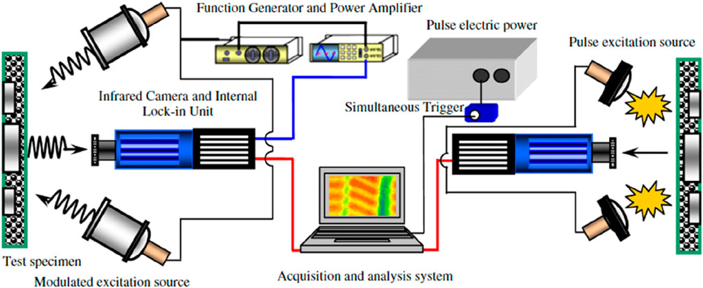
Figure 6. Schematic of the experimental setup of lock-in thermography and pulsed transient thermography (Junyan et al., 2013) Copyright 2012 by Elsevier Ltd.
Lock-in thermography follows the principle of periodic heating, typically using sinusoidally controlled halogen heat lamps. There is a heating period that lasts for at least one full excitation cycle. During the heating period, thermal images are recorded throughout. In the post-processing of the data, the phase, and amplitude of the periodic temperature change at the surface with respect to the applied heating cycle is obtained. This method has the advantage of faster processing as well as allowing us to visualize defects over a larger area of the workpiece (Junyan et al., 2012).
A few other techniques that have been used specifically for the NDT&E of C/C composites are Acoustic Emissions (AE), Electronic Speckle Pattern Interferometry (ESPI) (Figure 7), and Superconducting Quantum Interference Device (SQUID) current mapping. Acoustic Emissions NDT has been under some question with regards to whether it is NDT or DT. But keeping that aside, the peculiarity of AE lies in the fact that it can collect in situ information which means it has information regarding the entire load cycle of the composite and this information can be easily used to predict the possible method of failure for the composite.
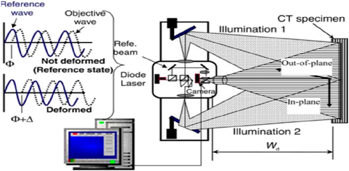
Figure 7. Schematic of Electronic Speckle Pattern Interferometry (3-D ESPI) system (Hatta et al., 2005) Copyright 2005 by Elsevier Ltd.
Unlike other NDT methods, the material is characterized only before or after testing. It can detect any defects and predict failure at an early stage. Computational efficiency is a major drawback of this method, given the data generated. T.H. Loutas et al. (Loutas and Kostopoulos, 2009) worked on experiments that showed that AE could pick up subsurface defects such as matrix-fiber debonding, matrix cracking, fiber bundle failure, and thermal stress relief.
X-rays are recommended for NDT due to the amount of energy they possess. In some cases, X-ray tomography (XRT) is used for NDE to quantify density within a larger object’s local region. The data results are represented as a numerical image known as a reconstructed slice. The image reveals two types of information. Firstly, it gives spatial information based on the dimension and position of eventual defects. Secondly, based on the signal, the intensity is representative of the density of the composite (Douarche et al., 2001).
XRT has been found to provide accurate results of density measurements of C/C composites. According to experiments conducted by N. Douarche et al. (Douarche et al., 2001) precisions of measurements of weighing density and (XRT) density are 1% and 3% respectively. This result is a clear indication that XRT can be used for local density maps in larger objects like aircraft brake discs.
Another method of interest for NDT of composites is a Superconducting Quantum Interference Device (SQUID). It utilizes an extremely sensitive magnet which is at least three orders more sensitive than conventional magnetic sensors. This increased sensitivity makes it easier for detection of subsurface defects in both ferromagnetic and non-ferromagnetic materials (Hatta et al., 2005).
Protective coatings for C/C composites
The following four processes, which are schematically depicted in Figure 8, are necessary for the oxidation of a substrate when a protective oxide coating is present on its surface. The rates of each step in a series would be the same in a steady state (Luthra, 1988).
1. Boundary layer diffuse of gas phase: Oxygen must diffuse across the boundary layer at the surface.
2. Diffusion of gas through the cracks: If the oxide layer is broken, oxygen can permeate through it and into the area where the substrate and oxide film come into contact. The fracture diameter influences the diffusion coefficient. The mean free route of the gas molecules is in the same order as the fracture size, however, the gas molecules bump into the walls at minuscule diameters. As a result, the effective diffusion coefficient decreases, and the material is transferred by Knudsen diffusion. Condensed phase diffusion: To oxidise the substrate, oxygen must diffuse through a nonporous oxide coating. The oxide’s fault structure affects the transport process.
3. Interface reaction: When oxygen reaches the substrate/oxide contact, it interacts to create a substrate oxidation product. At temperatures below roughly 500°C, the interface reaction regulates the oxidation of unconstrained carbon composites (Luthra, 1988).

Figure 8. A diagram depicting the probable rate-limiting phases during oxidation. (Luthra, 1988) Copyright 1988 by Elsevier Ltd.
The oxidation issue is a major impediment to the use of carbon/carbon (C/C) composites as high-temperature structural materials. Ceramic coating is an excellent method for preventing oxidation of C/C composites at high temperatures. Silicon-based coatings have a restricted temperature range for protection, limit its effectiveness in providing oxidation protection for C/C based components for thermal structures. At high temperatures, the oxidation of silicon-based ceramics produces a homogeneous and thick SiO2 glassy coating with limited oxygen permeability, which offers superior oxidation protection for C/C composites as represented in Figure 9 (Ghaffari et al., 2020).
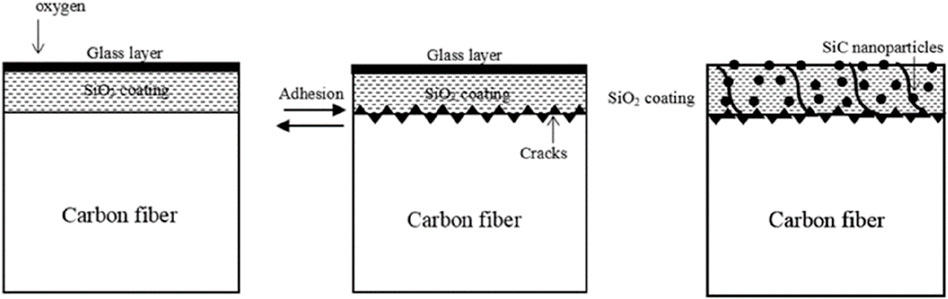
Figure 9. Oxidation mechanism of coated CF (Yang et al., 2018).
The main issue with C/C composites is that they react with the oxidizing atmospheres at a minimal temperature of 723 K despite being stable up to very high temperatures in the region of 3273 K or more in inert or vacuum conditions. Oxidation is the primary failure mechanism for C/C composites subjected to high-temperature environments (Rellick, 1990). As oxidation occurs on the surface, using an anti-oxidation coating is a viable technique to enhance the service life of C/C composites (Rellick, 1990).
Due to their excellent anti-oxidation properties, SiC ceramics are often used as coatings for oxidation protection. However, the difference in thermal expansion coefficients between SiC and C/C composites can cause the formation of microcracks in the SiC coating. Chromium silicide, which has a high melting point, good elevated-temperature creep strength, and oxidation resistance, is a potential structural material for high-temperature aerospace and energy production applications. Oxidation resistance of C/C composites with SiC coatings can be improved by injecting liquid CrSi2 into the pores and cracks of the SiC coating (Qian-Gang et al., 2006).
However, no such investigation on C/C composites built on thermosetting resin matrix combined with suitable filler is available. Molybdenum disilicate (MoSi2), an inorganic filler, would be the most appropriate for this application because of its outstanding mechanical qualities, high melting point (2030°C), and adequate oxidation reticence capabilities. The MoSi2 powders examined in this study may perform well as fillers to ameliorate the mechanical characteristics of composite materials. According to experimental findings, the addition of 12 wt. percent MoSi2 in the composites seems to boost the maximum degree of adhesion, whose bulk density is represented in Figure 10 (Park and Cho, 2000).
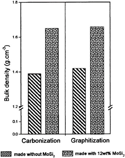
Figure 10. Bulk density of C–C composites made without MoSi2 and with 12 wt% MoSi2 as functions of HTT. (Park and Cho, 2000) Copyright 2000 by Elsevier Science Ltd.
Preparing ZrC doped C/C composites involved several steps, including soaking carbon felt in ZrOCl2 aqueous solution, densifying the material using Thermal Chemical Vapor Infiltration (TCVI), and graphitizing the material. The linear ablation rate declined linearly as ZrC concentration rose, although the bulk ablation rate increased initially before clearly declining. The addition of more ZrC significantly increased the ablation resistance of C/C composites. Although mechanical baring does not appear to be the primary mechanism, ablation was controlled by a heterogeneous mass movement (Sun et al., 2009). The composites’ carbon fibers were ablated thereafter and formed into needle-like forms. For pure C/C composites, the ablated surface of the carbon matrix was smooth and glossy, whereas for doped C/C composites, it was honeycombed and dull. Additionally, the oxidation resistance of the carbon fibers was better than that of the carbon matrix. However, the increased formation of ZrO2 weakened the bond between the fibers and the matrix, causing the fibers to separate from the matrix. When the ZrC contents reached 4.14 wt. Percent, the ablation resistance of carbon fibers was ineffective (Sun et al., 2009).
Polyacrylonitrile (PAN) fibers are pyrolyzed to create carbon fibers under controlled conditions. To create C/C composites, these fibers are then mixed with thermosetting resins and pyrolyzed. Before carbonization, PAN fibers must be thermally stabilized at 200°C–300°C in air. Carbon fibers produced by carbonization that have been thermally stabilized, or so-called oxidized fibers, have a high yield and outstanding mechanical qualities (Manocha et al., 1996).
Oxidant resistant coatings are suitable to protect C/C composites subjected to high temperatures. Mullite ceramic coatings have proven to be efficient for the high temperature coating. Mullite-coated SiC exhibited excellent oxidation resistance as SiO formation took place at the mullite-SiC interface, preventing the oxidation. Based on this research, it is possible to manufacture Al2O3 mullite-SiC multi-coatings with a thickness of roughly 200 mm using a two-step pack cementation technique. The C/C composites were successfully insulated from oxidation for 45 h at 1873 K, and the coated C/C composites loss rate was 1.51 × 10⁻⁴ g/cm2 per hour in weight during that period, which accounted for only 1.86% of weight loss (Jian-Feng et al., 2003).
Advanced coating techniques
It is well understood that carbon fiber-reinforced composites (CFCs) have a high specific strength and are durable, particularly at elevated temperatures above 1,000°C. The CFC must be protected against oxidation and corrosion and have additional thermophysical and chemical compatibility requirements when used in high-temperature applications.
It has been demonstrated that various technologies can be used to create coating architectures that are composed of dense ceramic top layers and porous base layers. Chemically inert surfaces should be provided on the top layers, which can act as diffusion barriers. In addition to providing structural support, porous base coatings also serve as a compensation mechanism between the brittle top coating with a low strain-to-failure and the thermophysical anisotropic carbon substrate. A functional ceramic top coat is also chemically compatible with the substrate (Friedrich et al., 2002).
Catering the industrial demand, the coatings have been studied and modified to exceed the conventional coating or composite coating capabilities which ranges from extreme environment performance, corrosion, abrasion, fatigue, erosion and friction.
Furthermore, the requirements for a protective advanced coating system would ideally be (Friedrich et al., 2002):
• Diffusion barrier function against liquids and gases
• Chemical compatibility
• Thermophysical compatibility (thermal expansion)
• Diffusion stability in contact with chemical compounds
• Low oxygen permeability
• Low intrinsic oxidation.
Although C/C composite materials offer many advantages for aero-engine applications, they also present new challenges due to their inherent properties, such as lower erosion resistance, poor thermal resistance, and poor electrical conductivity, compared to conventional aerospace metallic structures. It is necessary to investigate the erosion resistance of C/C composite materials in aero-engines since some components may be subjected to harsh erosive environments during operation.
There is a need to improve the ability of these composites to resist fire events since they are unable to withstand as high temperatures as traditional metallic components which comes with advanced coating techniques. Furthermore, several methods are used to protect C/C composites from oxidation, including surface treatments, adding inhibitors to the matrix, and applying outer coatings. Examples of these techniques include ZrC barrier coating on SiC-coated carbon and double SiC coatings, among others. The techniques for the different coating layers in dense advanced top coatings are shown in Figure 11 (Friedrich et al., 2002).
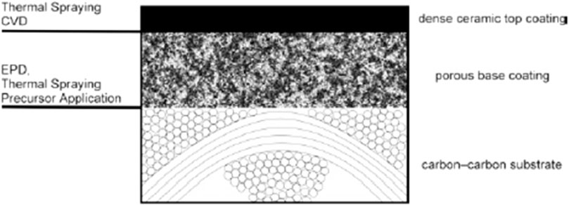
Figure 11. Suitable techniques for the different coating layers (Friedrich et al., 2002) Copyright 2002 by Elsevier Science (B)V.
Self-healing composites
As we have seen so far C/C exhibits exceptional thermal and mechanical properties which can be heavily used in critical structures. Given the intensive use of C/C composites in primary critical, and secondary critical structures, we will definitely face catastrophic failure in terms of matrix debonding, delamination, matrix microcracking and impact failure among other modes. To avoid a total replacement and high maintenance costs recent technologies have been developed for self-healing materials which can be used in critical structures.
There are mainly two types of self-healing mechanisms: extrinsic and intrinsic self-healing. Extrinsic healing involves the use of a healing agent which will be added externally whereas intrinsic healing depends on reversible molecular bonds (Das et al., 2016). Other classification of self-healing materials can be made based on the stimuli, materials can be classified as autonomic healing if there is no external stimuli and non-autonomic healing if there is external stimuli.
C/C composites fall under the category of Ceramic Matrix Composites (CMCs) which mainly face failure due to oxidation at higher temperatures. Self-healing for C/C composites would mainly focus on reducing the oxidation or stopping the damage done by this oxidation. They oxidise quickly above temperatures of 773 K in the atmosphere containing oxygen losing 40%–50% of their weight in less than a minute (Zhen et al., 2018), this severely damages their high-temperature applications.
To counter this loss in weight and subsequently, its properties, lots of advancements have been made around anti-oxidation coatings that can be applied on the surface of the parts that we manufacture. One such coating that has been developed in recent times is Zirconium diboride (ZrB2), it provides excellent thermal protection for objects on re-entry (>3000°C), it also provides exceptional thermal shock resistance and, mainly, oxidation resistance at elevated temperatures. However, its oxidation resistance properties are limited as Boron tends to form its oxide B2O3 (Haibo et al., 2016). This by-product has a low viscosity and evaporation temperature leaving the Zirconium exposed to the atmosphere causing it to oxidise and form ZrO2 which is a porous layer. Double coatings can be fabricated as an inner coating of SiC and an outer coating of glass-ceramic which are illustrated in Figure 12.

Figure 12. Illustration of the fabrication of the double coatings: I) inner SiC coating; and II) outer glass-ceramic coating. (Zhen et al., 2018). Copyright 2018 by Elsevier Ltd.
To counter this problem, it was proposed to add a layer of silicide such as SiC or Molybdenum Silicide (MoSi2). Upon oxidation of Boron to form B2O3, the oxidised Zirconium, ZrO2 will react with the silicide present to give ZrSiO4 which is thermally stable and has low permeability of oxygen thereby improving the oxidation resistance of the component (Haibo et al., 2016). This silicide coating not only improves the anti-oxidation properties but also the ablation properties of the part. By adding SiC nanowires under the ZrB2-SiC coating it improves the toughness of the coating on the composite (Zhang et al., 2015).
An alternative solution to the current problem is high-temperature glass ceramic coating. One of the main components of such a coating is SiO2, a high-temperature flow matter. While applying the coating a dense layer of low oxygen permeability SiO2 will form increasing the oxidation resistance. Luo et al. (Li et al., 2007) illustrated a method of applying a gradient self-healing coating of SiC-B4C/SiC/SiO2 with the inner layer being B4C and β-SiC. The middle layer was SiC-based, whereas the outer layer was SiO2, serving as an airproof barrier. The coating is also characterized for its excellent thermal shock resistance at temperatures around 1,500°C.
Anti-oxidation nature of the coating is not affected by superficial and inner cracks. The self-healing properties at different temperature regions are determined by deep lacerations. Starting from 500–700°C temperature region, where oxidation of B4C helps heal the cracks. Subsequently, from 800 to 1200°C, borosilicate glass typically forms, effectively filling the penetrative cracks. Much of this is attributed to the outstanding anti-oxidation properties of the coating. The borosilicate glass which forms is predominantly a B2O3-rich phase below temperatures of 1000°C and a Silica-rich phase at temperatures over 1000°C. Finally, for the range of 1300–1500°C, the weight loss rate slowly increases as the outer oxide layer gradually decreases (Zhang et al., 2015).
Previous studies have suggested that doping Si-based coatings will lower the oxygen permeability further. For this purpose, Rare-Earth (RE) doped Si-based coatings are utilised. One disadvantage of this coating is the cracking and spallation which occurs with excessive stresses accumulated during thermal corrosion over long periods (Wang et al., 2017).
Recent developments in self-healing coatings have also given rise to YSZ (Y2O3 partially stabilized ZrO2) coatings which are commonly used for Thermal Barrier Coatings (TBCs). An illustration of the healing process in represented in Figure 13. YSZ, due to its composition, operates within a narrow range where the ferroelastic toughening mechanism is effective. This property makes it robust. For achieving higher temperature usage there have also been proposals recently to fuse YSZ technology with RE doped Si-based ceramics. From previous studies, it has been revealed that ZrO2 is conducive to forming a stable Zr-La-Si-O heterogeneous oxide glass film under high temperature in the fused system of YSZ and RE-Si (Wang et al., 2017).
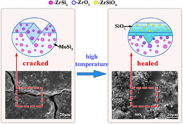
Figure 13. Illustration of the healing process of the composites with anti-oxidation layer of ZrSi2 (Wang et al., 2018) Copyright 2018 by Elsevier (B)V.
Corrosion and wear
Due to their inert nature, Carbon-Carbon (C/C) materials have high corrosion and oxidation resistance. Furthermore, they demonstrate significant durability when it comes to friction and wear. Composites made from carbon and carbon have improved thermal, mechanical, and friction properties compared to advanced ceramics. At temperatures exceeding 3000°C, C/C composites exhibit excellent dimensional stability, as compared to the metals that undergo drastic deterioration in the same condition. Carbon-Carbon (C/C) composites’ properties are greatly influenced by their manufacturing methods. A manufacturer’s expertise lies in combining processes to achieve specifically tailored properties despite knowing the general production technology (Saifeldein, 2015).
A carbon-fibre-reinforced-carbon matrix composite (FRC) is a composite material formed by combining carbon fibers with graphite matrix. The thermal expansion properties of Carbon-Carbon composites are superior to those of other composite materials or metals. The low coefficient of thermal expansion of carbon-carbon composites (C/C), 0.3–0.5 mm in the fibre direction and 0.5–0.8 mm in the perpendicular direction allow these composites to absorb heat without deformation (Saifeldein, 2015). In the fibre direction and perpendicular direction, wear rates are (0.05–0.1 mm) and (0.1–0.3 mm). When a load is applied to a composite, it is first absorbed by the matrix phase and then transferred to the reinforcement phase, enhancing the overall strength. The physical properties of C/C composites are primarily determined by the reinforcing fibers.
Tribological properties
C/C composites tend to have unsuitable behavior under adverse conditions and are rarely used in wet and corrosive environment. However, C/C-SiC composites are used in brake friction materials for automotive and aerospace applications where they are subjected to wet and high-speed braking (Kumar and Srivastava, 2016).
Previous studies have observed that the frictional stability of carbon largely depends on a few factors. Factors such as the adsorption of water vapor, wear, and the transition to high friction, which increase with the partial pressure of vapor, play a role. For a series of n-paraffins, friction also increases with chain length. The peak transition temperature is 400°C, making ambient temperature control difficult. This temperature is a critical threshold for the material’s frictional properties, beyond which significant changes may occur. Not many studies have involved research on improving friction and wear properties; hence, we have to resort to additives and modifications to amplify the properties at exceeding temperatures while maintaining the material’s stability (Matsui and Yasutake, 1998).
Dry friction tests on C/C composites up to 1000°C were conducted to evaluate the oxidation of carbon and the temperature associated with water vapor evaporation. An example of sliding friction is shown in Figure 14. Other studies were conducted by incorporating additives, hydrocarbons with different carbon numbers and inorganic compounds that are water-soluble. The friction and wear properties from the experiments increased proportionally to the decrease in humidity present. The increase in friction and wear was much more drastic in vacuum conditions (Matsui and Yasutake, 1998).

Figure 14. Optical microscopy views of the worn surfaces of CFRC pins, (A, C), and discs, (B, D), resulting from sliding at room temperature, (A, B), and T = 600°C, (C, D) (Gomes et al., 2001) Copyright 1988 by Elsevier.
Another observation was a sudden increase in the friction coefficient at 200°C with an increase in temperature. The friction and wear showed a directly proportional relationship up to 200°C, which rose to a maximum and gradually decreased with temperatures greater than 200°C. The peak/transition temperature increased with the addition of a high carbon number of hydrocarbons. It showed an even greater increase with the incorporation of water-soluble inorganic compounds (Matsui and Yasutake, 1998).
The friction coefficient for the oil-absorbed carbon-epoxy composites showed a sharp increase followed by a period of steady state, which was consistent with the observations by Ayatollahi et al. (Ayatollahi et al., 2017). It has been previously established that tribological behavior is heavily dependent on surface conditions with regard to PAN-CVI C/C composites, where PAN as a precursor and CVI as a fabrication technique which allows the production of high-quality C/C composites with desired properties (Kuo et al., 2005). Oil, however, is hardly talked about when discussed. Studies reveal changes in mechanical properties for oil-adsorbed C/C composites (Bi et al., 2008). There is a sizable decrease in flexural strength and flexural modulus of the composite after multiple cycles due to oil burning and, consequently, fiber-matrix deterioration (Bi et al., 2008).
Creep and fatigue failure
C/C composites display excellent thermal resistance and mechanical properties such as strength with low weight requirements and are used in aerospace applications. We also need insight into the fatigue properties and failure modes to put these composites to more efficient usage. Moreover, because of the high-temperature applications of C/C composites, the mechanical properties they exhibit under these conditions and the kinds of failure they experience while under these thermo-mechanical loads are worth mentioning.
The fatigue fracture of C/C composites can essentially be classified into three types:
(1) Low-stress region: the interfacial damage improves the residual strength.
(2) Region up to fatigue limit: The strength of fibers will degrade due to the surface experiencing wear, and the fractured core grows with fatigue cycles.
(3) High-stress region: the failure is similar to failure experienced when exposed to static tensile testing (Goto et al., 2005).
Studies done by Leonas et al. (Leanos and Prabhakar, 2015) investigated the failure modes of C/C composites when exposed to thermal shock. The study involved experiments where the composite was exposed to thermal shock at different peak temperatures for a number of cycles, a case of which is shown in Figure 15. Mechanical properties and microstructure evolution were parameters evaluated to provide an idea into the modes of failure. The study by Leanos and Prabhakar (2015), concluded tow/matrix debonding and interlayer shear failure were the primary mechanisms in 2D C/C composites specimens, subjected to high-stress concentrations between the plies.
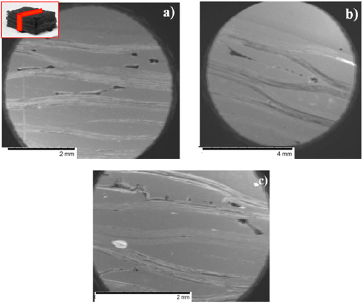
Figure 15. SEM micrograph of (A) pristine (B) 400°C, and (C) 700°C of polished 2D C/C composite specimen after compressive test of three cycles (Leanos and Prabhakar, 2015) Copyright 2015 by Elsevier Ltd.
Sines et al. (sines et al., 1989) showed the creep behavior of uniaxial C/C composites at high temperatures and stresses through a series of experiments. The creep curve obtained showed the initial large transient stage to be followed by a steady state response, which a Dorn-type creep model can help. The activation energy reported by Sines et al. (sines et al., 1989) in the studies conducted is 1082 kJ/mol. The activation energy also had the same values reported for the graphitization of different pyrolytic carbons (sines et al., 1989; Gvishi et al., 1992).
Machining and drilling of C/C composites
Machining and finishing components to provide the required surface finish is an essential aspect of choosing the material for a particular application. Although most components made from composite materials are manufactured to near net shape, machining these components is necessary to meet dimensional precision and provide better performance.
Machining and drilling of composites typically causes delamination, which can lead to a loss of desired properties in terms of strength and fatigue failure. C/C composites are difficult to machine using conventional machining methods due to their anisotropy, brittleness, and intrinsic hardness.
The traditional machining methods are not suitable for machining C/C composites as along with the above-mentioned properties, they also lead to workpiece damage through chipping, cracking, delamination, and high wear on the cutting tool (Guu et al., 2001). Among the non-conventional machining techniques, the most commonly recommended method is Electric Discharge Machining (EDM) represented in Figure 16.
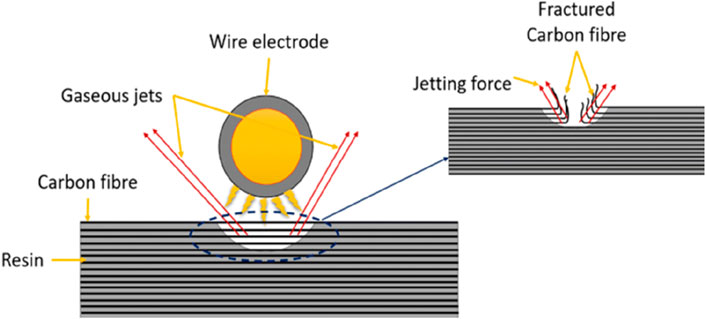
Figure 16. EDM of Carbon Fibre (Abdallah et al., 2021) Adapted under CC BY 4.0.
EDM is typically used for machining hard, strong, wear and temperature-resistant materials, which is the case with C/C composites. Since in EDM the tool and the workpiece do not come into contact we can eliminate vibrations and chatter (Guu et al., 2001). Another non-conventional machining method that is applicable is Laser cutting. Gureev et al. (Gureev et al., 1999) have experimentally established the effective usage of continuous wave laser radiation could be used in the machining and pattern cutting of C/C composites. George et al. (George P. et al., 2004) have worked on establishing an empirical relationship as a function of EDM process parameters. This has been used to analyse the machinability of C/C composites.
Another study (George P. et al., 2004) was conducted to analyse the process parameters in EDM to determine how it would determine the machinability of the composite. The most significant process parameter was found to be pulse current. Other significant parameters include gap voltage followed by pulse on time. These parameters have been compared with respect to their material removal rate in Figure 17. With existing models, it is possible to successfully calibrate the process parameters in order to achieve desirable results. Delamination of the workpiece caused by EDM strongly affects the measurement of overcut and loss of circularity (Gureev et al., 1999).
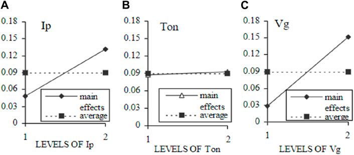
Figure 17. Variation of Material Removal Rate in EDM with respect to (A) Pulse current, (B) Pulse on time, (C) Gap voltage (George et al., 2004) Copyright 2003 by Elsevier (B)V.
Gureev et al. (1999) have researched the effects of process parameters on the surface roughness (Ra) of the finished component using a profilometer. It was observed that one of the main parameters, Pulse Energy, determined the delamination effects. Smaller pulse energy helps prevent delamination defects around the holes of the top and bottom surface of the workpiece. Delamination on the cutting edge, however, increases with the increase in temperature. This increase in temperature is caused by an increase in discharge energy. Not only is there an increase in delamination but another issue that arises is the increase in surface roughness as well as creating a much larger recast layer (George P. et al., 2004).
Another important non-conventional machining process used is Abrasive Flow Machining (AFM). The process of AFM is illustrated in Figure 18. AFM is generally used when the workpiece is intricate and certain parts are difficult to reach and need to be deburred or polished. It is done by getting a semi-solid medium to flow across the surface. The fluid medium used to transport the abrasive particles is generally a polymer. The polymers transmit the extruding force while the abrasives act as the cutting edge and continuously remove materials from the workpiece. The abrasives employ cutting, ploughing, rubbing, or a combination of these actions to remove material from the surface.
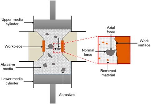
Figure 18. Illustration of Abrasive Flow Machining Process (Dixit et al., 2021) CC BY 4.0.
The abrasive materials, being small in nature, have a very small material removal rate but this also ensures a better surface finish of the product. Some of the process parameters that affect the surface roughness of the finished workpiece include: extrusion pressure, flow volume, velocity and viscosity of media, abrasives, workpiece configuration and flow pattern (Rhoades, 1991). William et al. (Williams and Rajurkar, 1992) found that the extrusion pressure and viscosity of an abrasive medium significantly affect the material removal rate and surface roughness. By varying the process parameters, it is possible to obtain optimal conditions for the best results while working with C/C composites.
Ravikumar et al. (2012) studied the effects of a few parameters on surface roughness. The parameters include: abrasive particle size (mesh size), extrusion pressure, the viscosity of the medium, abrasive loading, and the number of cycles. Surface roughness was seen to increase to a maximum with increase in all parameters, reaches a maximum and gradually decreases. Other derivatives of AFM include centrifugal force-assisted AFM. This is being researched in order to minimise residual stress, improve the finishing rate, and achieve better surface integrity (Ravikumar et al., 2012).
Drilling
C/C composites display excellent mechanical properties that makes it a desirable material to be used in critical applications like the aerospace industry and brake pads. However, the brittle nature of C/C composites complicates the drilling process. The woven nature of carbon fibers wears down the cutting edge of the tool, leading to fibers being pulled-out, leading to machining defects (Kumar et al., 2020). Therefore, it is favourable to take an approach similar to machining, and non-contact drilling.
Recent research has been conducted in the field of Electrical Discharge Drilling (EDD) which is a non-contact machining process whereby the material is removed by recurring sparks between tool and workpiece which forms micro-holes (Kumar et al., 2020). EDD is a combination of conventional drilling processes and Electric Discharge Machining and is hence referred to as a collaborative hybrid machining process (HMP) of the former two.
The material removal in EDD does not occur through contact as in the conventional drilling process, rather it relies on repeated melting and evaporation while the tool simultaneously rotates to assist the material removal by evacuating the debris from the machining area effectively (Kumar et al., 2020).
Processes for reinforcing carbon for aerospace
In the aerospace industry, carbon fiber is widely preferred due to its superior mechanical and thermal properties. However, it has certain drawbacks. The surface of carbon fiber is very smooth and chemically inert, which can lead to poor adhesion between the fiber and the matrix, ultimately affecting the properties of carbon fiber reinforced polymers (CFRPs). To address this issue, carbon nanotubes (CNTs) were introduced. Adding CNTs significantly enhances the mechanical properties and thereby reinforces the composite (Shirvanimoghaddam et al., 2017). Furthermore, it possesses a specific microstructure and unusually high thermal conductivity.
Graphene oxide (GO) reinforcement has also been tested with carbon fiber. Observations under SEM at 20kV showed that GO sheets were chemically grafted onto the carbon fiber surface, forming a new hierarchical structure. The functionalization improved the carbon fibre’s surface roughness through GO and CNT grafting. The interfacial strength of GO and CNT grafted CF composites increased due to factors like improved surface energy and wettability of CF-GO-CNTs from the abundant polar groups on GO and CNTs, enhanced mechanical interlocking between the carbon fiber and epoxy matrix due to increased fiber surface area, and forms chemical bonds at the GO/CNTs/CF-matrix interface. Figure 19 compares the interfacial shear strength (IFSS) of these types of composites (Gao et al., 2016).

Figure 19. IFSS (Interfacial shear strength) of carbon fibre composites (Gao et al., 2016) CC BY 4.0.
Pyrolytic carbon (PyC) is crucial in high-performance materials, such as carbon/carbon composites used in aerospace for heat shielding and friction-resistant brake pads in commercial aircraft. The elastic properties of porous nanotextured PyC were modeled using irregularly shaped pores (Drach et al., 2011). Due to significant differences in the dimensions of inscribed and circumscribed ellipsoids, their analysis was not feasible. The parameters characterizing the contribution of individual pores to the effective elastic moduli were similar. When comparing long cylindrical pores to 2:1 spheroidal shapes, the spheroidal approximation provided more accurate predictions of effective Young’s moduli (Drach et al., 2011).
Three-dimensional (3D) woven composites are widely used in aerospace industry. A model reference standard was created to predict the material response of composites reinforced with a 3D woven ply-to-ply fiber architecture under single bolt, double-shear bearing conditions. The predicted material behavior, including stress-strain response trends and failure modes in the progressive damage model, was validated by experimental results (Warren et al., 2016).
When tested at high temperatures, carbon/carbon composites show a 10–20% increase in mechanical properties at 2,000°C in an inert atmosphere. The reinforcing fibers are more anisotropic than the carbon matrix (Manocha, 2003). The best ways to improve oxidation and ablation resistance in C/C composites include matrix modification and coating. These methods involve optimizing carbon fiber weave structures, controlling pyrolytic carbon texture, modifying the carbon matrix, and applying anti-ablative ceramic layers (Warren et al., 2016, Jin et al., 2018).
Chemical Vapor Infiltration (CVI) offers significant benefits, such as low preparation temperatures that prevent damage to the carbon matrix and controlled composition and structure of coatings (Jin et al., 2018). Carbon/carbon (C/C) composites are promising for high-temperature structural applications in thermal protection systems due to their excellent high-temperature properties (Jin et al., 2018).
Carbon/carbon (C/C) composites are ideal for aerospace applications due to their lightweight, superior mechanical properties at high temperatures, good thermal properties, and excellent friction properties. The mechanical and thermal properties of C/C composites are intrinsically linked to the carbon microstructure (Buchgraber, 2003). Three types of carbon fiber reinforcements are used in C/C composite brake discs: carbon fabric laminates, semi-random chopped carbon fibers, and laminated carbon fiber mats with cross-ply reinforcement (Awasthi and Wood 1988).
The pyrolytic carbon matrix is obtained via chemical vapor deposition (CVD). Glassy carbon is derived from the carbonization of high-char-yield resin, used to consolidate carbon fibers into disks or densify porous disks by resin impregnation during later processing stages (Awasthi and Wood, 2008). The damage tolerance behaviour of unidirectionally reinforced C/C composites was analyzed using various experimental techniques (Chowdhury et al., 2018):
(1) Digital Image Correlation (DIC) analyses showed that irreversible cyclic damage accumulates in the form of localized strain bands parallel to fibers, reducing the composite’s overall stiffness over several cycles.
(2) Fiber/matrix interface debonding during cracking causes pervasive fiber bridging, significantly decelerating crack growth, confirmed via CT scan analysis.
Post-fracture crack surface studies revealed extensive fiber pull-out-dominated damage progression. CT scans can observe fiber matrix compounds, as shown in Figure 20. The crack advances through matrix tearing assisted by coalescence with pre-existing microscopic pores (Chowdhury et al., 2018).
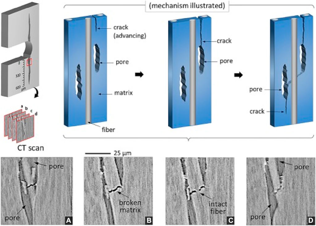
Figure 20. CT scan images (A through D) at the early stage show how a growing crack coalesces with an existing pore, which then merges a with a neighboring pore. The fiber remains intact (until the final fracture) while the merger of two pores advances the crack even further down. (Chowdhury et al., 2018) Copyright 2018 Elsevier Ltd.
Microstructure plays an important role in understanding the performance of C/C composites, as it provides information about F/M distribution, pore dispersion, isotropy and anisotropy of the matrix formation, and extent of damage during processing or testing could be assessed. A study by Devi and Rao (1993) on various matrix precursors, specifically resin (R) and pitch (P) for skeleton formation, revealed that composites processed with pitch material exhibited slightly higher porosity. This is attributed to the higher density of carbon derived from pitch. Both the bulk matrix and the matrix surrounding the filament displayed a lamellar structure, indicating efficient graphitization.
C/C composites are unique ceramic engineering materials exhibiting brittle to pseudoplastic behavior, where carbon fiber is reinforced into the carbonaceous matrix forming C/C composites. High specific strength along with the stiffness of carbon fibers, and refractory properties of carbon matrix combining together to form a C/C composite is the goal (Kebede, 2021). When fibers are laid in near-net shape with multidirectional reinforcements results in an ideal high temperature tolerant material structure (Devi and Rao, 1993).
Aerospace applications
Developed more than 30 years ago to meet the needs of space missions, C/C composites were widely employed in spacecraft applications. As a part of NASA’s Apollo spacecraft’s heat shield system, C/C composites are recognized as high-performance engineering materials with potential uses in high-temperature industries, such as utilization in projectile missile and rocket applications and space payload structural applications (Singh et al., 2007).
Due to their favorable characteristic applications, including excellent anti-friction and anti-wear and great thermal shock resistance, C/C composites are involved in various thermal protection systems, making C/C composites a significant candidate material in the aerospace area (Simil et al., 2013). Along with the rapid expansion of the aerospace sector, the intense operational environment faced by rocket engines driven with solid propellants or solid propellant rockets constitutes a significant issue with materials to withstand extreme temperatures.
C/C composite is the chosen option for any application involving the use of mechanical fasteners at high temperatures which in turn also aids weight reduction. This is due to the fact that the performance requirements and the operating conditions in a loaded state of C/C composite is exceptional at high temperatures while may not be as admirable as that of metals at ambient room temperatures (Simil et al., 2013).
Carbon-Carbon (C/C) composites are favoured in aerospace and related applications that face hostile thermal conditions because they offer good properties such as low density, excellent ablation, high specific strength/modulus, low coefficient of thermal expansion, and thermal shock resistance at high temperatures (Virmani et al., 2021). Because of these properties, C/C composites are interesting aerospace candidates for manufacturing components like leading edges of turbine engines, aircraft brake pads, rocket and jet nose tips and nozzles for hypersonic re-entry vehicles (Singh et al., 2007). The ablation resistance of a C/C composite can be greatly influenced by adding an overlay layered coating on the surface of the material as discussed above.
Characteristics such as great dimensional stability put them in place as a suitable choice for applications involving outstanding thermo-structural components like turbine engines, space payload structural applications, and heat shields of missiles, rockets, or space vehicles. Hence, it can be correctly said that these materials meet all of the criteria for space structure requirements (Singh et al., 2007). Ceramics based on ZrB2 have vital applications in thermal protection systems and other components for hypersonic aircraft vehicles. Because of their exceptional features, such as high melting point, high strength, and superior oxidation resistance at high temperatures, ZrB2-based materials have been identified as attractive candidates for use in aerospace applications (Virmani et al., 2021).
Conclusion
Carbon-carbon (C/C) composites comprise carbon fibers held together by a carbon matrix. They are lightweight materials with outstanding thermal shock resistance, toughness, ablation resistance, and high-speed friction properties, capable of maintaining structural integrity at extreme temperatures. The strong connection between the matrix and fibers improves several characteristics. As a result, fiber treatments and matrix manufacturing procedure changes are being researched to tune the interfacial strength for various composite applications and property needs. Advanced carbon-carbon composite materials are extensively employed in various aircraft and ground-based applications. The development of technologies for oxidation protection of carbon materials has received a lot of interest. One of the most common techniques is to add coatings on the article surface, such as SiC, MoSi2, and ZrSiO4.
Because of the self-sealing performance of SiO2 generated from SiC oxidation, the SiC ceramic possesses excellent anti-oxidation capabilities. There is little information on the oxidation performance of ZrB2-MoSi2 coatings produced via slurry painting. Incorporating high interlaminar strength into composites is an efficient technique to improve their mechanical performance, particularly under extreme loading circumstances.
The addition of CNTs can change its surface state from smooth to rough, considerably increasing the number of nucleation locations. Second, CNTs are mostly made of carbon, which is comparable to CCs. CNTs may grow directly on carbon fibers with excellent F/M interface bonding. Third, carbon nanotubes (CNTs) are effective reinforcement and are widely used in structural composites. C/C composites have various qualities that may be adjusted by selecting component materials, fiber orientations, and production details.
Author contributions
NA: Conceptualization, methodology, software, formal analysis, Writing–original draft. AR: Conceptualization, methodology, software, formal analysis, Writing–original draft. KB: Writing–original draft. SV: Writing–original draft. AF: Writing–original draft. UC: Conceptualization, methodology, software, formal analysis, Validation, supervision, project administration, Data curation, Writing—original draft. DS: Conceptualization, methodology, software, formal analysis, Funding acquisition, Writing–review and editing, visualization, Validation, supervision, project administration, Data curation. AP: Validation, supervision, project administration, Writing–review and editing, visualization. RV: Data curation, Writing–review and editing, visualization.
Funding
The author(s) declare that no financial support was received for the research, authorship, and/or publication of this article.
Conflict of interest
The authors declare that the research was conducted in the absence of any commercial or financial relationships that could be construed as a potential conflict of interest.
Publisher’s note
All claims expressed in this article are solely those of the authors and do not necessarily represent those of their affiliated organizations, or those of the publisher, the editors and the reviewers. Any product that may be evaluated in this article, or claim that may be made by its manufacturer, is not guaranteed or endorsed by the publisher.
References
Abdallah, R., Soo, S. L., and Hood, R. (2021). The influence of cut direction and process parameters in wire electrical discharge machining of carbon fibre–reinforced plastic composites. Int. J. Adv. Manuf. Technol. 113 (5–6), 1699–1716. doi:10.1007/s00170-021-06641-2
Awasthi, S., and Wood, J. L. (2008). Carbon/carbon composite materials for aircraft brakes. Proc. 12th Annu. Conf. Compos. Adv. Ceram. Mater. Part 1 2 Ceram. Eng. Sci. Proc. 9 (7/8), 553–559. doi:10.1002/9780470310496.ch4
Ayatollahi, M. R., Moghimi Monfared, R., and Barbaz Isfahani, R. (2017). Experimental investigation on tribological properties of carbon fabric composites: effects of carbon nanotubes and nano-silica. Proc. Institution Mech. Eng. Part L J. Mater. Des. Appl. 233 (5), 874–884. doi:10.1177/1464420717714345
Awasthi, S., and Wood, J. L. (1988). “Carbon/carbon composite materials for aircraft brakes,” in Proceedings of the 12th annual conference on composites and advanced ceramic materials: ceramic engineering and science proceedings, New Delhi, India, (Hoboken, NJ, United Status: John Wiley & Sons, Inc.), 553–559.
Bi, Y., Luo, R., Li, J., Feng, Z., and Jin, Z. (2008). The effects of the hydraulic oil on mechanical and tribological properties of C/C composites. Mater. Sci. Eng. A 483-484, 274–276. doi:10.1016/j.msea.2006.12.152
Buchgraber, W. (2003). Carbon/carbon composite friction discs for aerospace. Werkstofftech 34, 317–321. doi:10.1002/mawe.200390067
Chowdhury, P., Sehitoglu, H., and Rateick, R. (2018). Damage tolerance of carbon-carbon composites in aerospace application. Carbon 126, 382–393. doi:10.1016/j.carbon.2017.10.019
Das, R., Melchior, C., and Karumbaiah, K. M. (2016). Self-healing composites for aerospace applications. Adv. Compos. Mater. Aerosp. Eng., 333–364. doi:10.1016/b978-0-08-100037-3.00011-0
Dekeyrel, A., Dourges, M.-A., Weisbecker, P., Pailler, R., Allemand, A., Ténèze, N., et al. (2013). Characterization of carbon/carbon composites prepared by different processing routes including liquid pitch densification process. Compos. Part A Appl. Sci. Manuf. 49, 81–88. doi:10.1016/j.compositesa.2013.02.010
Devi, G. R., and Rao, K. R. (1993). Carbon carbon composites: an overview. Def. Sci. J. 43 (4), 369–383. doi:10.14429/dsj.43.4291
Dixit, N., Sharma, V., and Kumar, P. (2021). Research trends in abrasive flow machining: a systematic review. J. Manuf. Process. 64, 1434–1461. doi:10.1016/j.jmapro.2021.03.009
D Macías, J., Bante-Guerra, J., Cervantes-Alvarez, F., Rodrìguez-Gattorno, G., Arés-Muzio, O., Romero-Paredes, H., et al. (2019). Thermal characterization of carbon fiber-reinforced carbon composites. Appl. Compos. Mater. Springer Verl. Ger. 26 (1), 321–337. doi:10.1007/s10443-018-9694-0
Douarche, N., Rouby, D., Peix, G., and Jouin, J. (2001). Relations between X-ray tomography, density and mechanical properties in carbon–carbon composites. Carbon 39 (10), 1455–1465. Crossref Elsevier BV. doi:10.1016/s0008-6223(00)00196-2
Drach, B., Tsukrov, I., Gross, T., Dietrich, S., Weidenmann, K., Piat, R., et al. (2011). Numerical modeling of carbon/carbon composites with nanotextured matrix and 3D pores of irregular shapes. Int. J. Solids Struct. 48 (18), 2447–2457. doi:10.1016/j.ijsolstr.2011.04.021
Friedrich, C., Gadow, R., and Speicher, M. (2002). Protective multilayer coatings for carbon–carbon composites. Surf. Coatings Technol. 151–152, 405–411. doi:10.1016/s0257-8972(01)01655-3
Gao, B., Zhang, R., He, M., Sun, L., Wang, C., Liu, L., et al. (2016). Effect of a multiscale reinforcement by carbon fiber surface treatment with graphene oxide/carbon nanotubes on the mechanical properties of reinforced carbon/carbon composites. Compos. Part A Appl. Sci. Manuf. 90, 433–440. doi:10.1016/j.compositesa.2016.08.012
George, P., Raghunath, B., Manocha, L., and Warrier, A. M. (2004b). Modelling of machinability parameters of carbon–carbon composite—a response surface approach. J. Mater. Process. Technol. 153 (154), 920–924. doi:10.1016/j.jmatprotec.2004.04.354
George, P. M., Raghunath, B. K., Manocha, L. M., and Warrier, A. M. (2004). EDM machining of carbon–carbon composite—a Taguchi approach. J. Mater. Process. Technol. 145 (1), 66–71. doi:10.1016/s0924-0136(03)00863-x
Ghaffari, S., Makeev, A., Seon, G., Cole, D. P., Magagnosc, D. J., and Bhowmick, S. (2020). Understanding compressive strength improvement of high modulus carbon-fiber reinforced polymeric composites through fiber-matrix interface characterization. Mater. &Amp; Des. 193, 108798. doi:10.1016/j.matdes.2020.108798
Gomes, J. R., Silva, O. M., Silva, C. M., Pardini, L. C., and Silva, R. F. (2001). The effect of sliding speed and temperature on the tribological behaviour of carbon–carbon composites. Wear 249 (3-4), 240–245. doi:10.1016/s0043-1648(01)00554-3
Goto, K., Furukawa, Y., Hatta, H., and Kogo, Y. (2005). Fatigue behavior of 2D laminate C/C composites at room temperature. Compos. Sci. Technol. 65 (7-8), 1044–1051. doi:10.1016/j.compscitech.2004.09.031
Gureev, D. M., Kuznetsov, S. I., and Petrov, A. L. (1999). Laser-beam pattern cutting of carbon-based composites. J. Russ. Laser Res. 20 (4), 349–361. doi:10.1007/bf02508655
Guu, Y. H., Hocheng, H., Tai, N. H., and Liu, S. Y. (2001). Effect of electrical discharge machining on the characteristics of carbon fiber reinforced carbon composites. J. Mater. Sci. 36, 2037–2043. doi:10.1023/A:1017539100832
Gvishi, M., Kahn, A. H., and Mester, M. L. (1992). Eddy current testing of carbon-carbon composites. Rev. Prog. Quantitative Nondestruct. Eval., 289–297. doi:10.1007/978-1-4615-3344-3_36
Haibo, O., Cuiyan, L., Jianfeng, H., Liyun, C., Jie, F., Jing, L., et al. (2016). Self-healing ZRB 2 –SIO 2 oxidation resistance coating for sic coated carbon/carbon composites. Corros. Sci. 110, 265–272. doi:10.1016/j.corsci.2016.04.040
Han, B. (2018). Research and application of functionally gradient materials. IOP Conf. Ser. Mater. Sci. Eng. 394, 022065. doi:10.1088/1757-899x/394/2/022065
Hatta, H., Aly-Hassan, M. S., Hatsukade, Y., Wakayama, S., Suemasu, H., and Kasai, N. (2005). Damage detection of C/C composites using ESPI and Squid Techniques. Compos. Sci. Technol. 65 (7-8), 1098–1106. doi:10.1016/j.compscitech.2004.11.017
Huang, S., Fu, Q., Yan, L., and Kasal, B. (2021). Characterization of interfacial properties between fibre and polymer matrix in composite materials – a critical review. J. Mater. Res. Technol. 13, 1441–1484. doi:10.1016/j.jmrt.2021.05.076
Jian-Feng, H., Xie-Rong, Z., He-Jun, L., Xin-Bo, X., and Min, H. (2003). Mullite-Al2O3-SiC oxidation protective coating for carbon/carbon composites. Carbon 41 (14), 2825–2829. doi:10.1016/s0008-6223(03)00397-x
Jin, X., Fan, X., Lu, C., and Wang, T. (2018). Advances in oxidation and ablation resistance of high and ultra-high temperature ceramics modified or coated carbon/carbon composites. J. Eur. Ceram. Soc. 38 (1), 1–28.
Junyan, L., Liqiang, L., and Yang, W. (2013). Experimental study on active infrared thermography as a NDI tool for carbon–carbon composites. Compos. Part B Eng. 45 (1), 138–147. doi:10.1016/j.compositesb.2012.09.006
Junyan, L., Qingju, T., and Yang, W. (2012). The study of inspection on SiC coated carbon–carbon composite with subsurface defects by lock-in thermography. Compos. Sci. Technol. 72 (11), 1240–1250. doi:10.1016/j.compscitech.2012.04.010
Kebede, F. (2021). Carbon-carbon composite application areas and limitations. J. Ergonomics 11, 283.
Kinjo, T., Takano, S., Hasegawa, K., Ebato, O., and Uruno, T. (1990). Development of advanced carbon-carbon composite for spaceplane application. Kawasaki Steel Tech. Rep. 23.
Kumar, P., Shekhar, A., and Yadav, S. K. S. (2020). Experimental analysis of electrical discharge drilling (EDD) of carbon-carbon composite. Mater. Today Proc. 22, 3106–3115. doi:10.1016/j.matpr.2020.03.447
Kumar, P., and Srivastava, V. K. (2016). Tribological behaviour of C/C–sic composites-a review. J. Adv. Ceram. 5 (1), 1–12. doi:10.1007/s40145-015-0171-z
Kuo, H. H., Lin, J. H. C., and Ju, C. P. (2005). Effect of a post-treatment on tribological behavior of PAN/CVI and pitch/phenolic/CVI-based C/C composites. J. Mater. Sci. 40 (12), 3263–3265. doi:10.1007/s10853-005-2697-x
Leanos, A. L., and Prabhakar, P. (2015). Experimental investigation of thermal shock effects on carbon–carbon composites. Compos. Struct. 132, 372–383. doi:10.1016/j.compstruct.2015.05.038
Li, C., and Xian, G. (2019). Influence of elevated temperature treatment on the microstructures and mechanical properties of carbon fibers in argon environment. J. Mater. Eng. Perform. 28, 7804–7815. doi:10.1007/s11665-019-04480-7
Li, J., Luo, R., Lin, C., Bi, Y., and Xiang, Q. (2007). Oxidation resistance of a gradient self-healing coating for carbon/carbon composites. Carbon 45 (13), 2471–2478. doi:10.1016/j.carbon.2007.08.036
Li, Y., Guo, L., Li, H., Ma, H., and Song, Q. (2017). Effects of carbon nanotubes by electrophoretic deposition on interlaminar properties of two-dimensional carbon/carbon composites. J. Wuhan Univ. Technology-Mater. Sci. Ed. 32 (5), 994–1000. doi:10.1007/s11595-017-1701-z
Loutas, T., and Kostopoulos, V. (2009). Health monitoring of carbon/carbon, woven reinforced composites. Damage assessment by using advanced signal processing techniques. Part I: acoustic emission monitoring and damage mechanisms evolution. Compos. Sci. Technol. 69 (2), 265–272. doi:10.1016/j.compscitech.2008.07.020
Luthra, K. L. (1988). Oxidation of carbon/carbon composites—a theoretical analysis. Carbon 26 (2), 217–224. doi:10.1016/0008-6223(88)90040-1
Maalawi, K. (2018) Modeling and applications of FGMs in aerospace structures. doi:10.4172/2168-9792-C3
Manocha, L., Bhatt, H., and Manocha, S. (1996). Development of carbon/carbon composites by co-carbonization of phenolic resin and oxidised pan fibers. Carbon 34 (7), 841–849. doi:10.1016/0008-6223(95)00201-4
Manocha, L. M. (2003). High performance carbon-carbon composites. Sadhana 28, 349–358. doi:10.1007/BF02717143
Matsui, A., and Yasutake, A. (1998). Improvement of tribological properties of C/C composites at high temperatures. Tribol. Trans. 41 (1), 124–128. doi:10.1080/10402009808983730
Park, S. J., and Cho, M. S. (2000). Effect of anti-oxidative filler on the interfacial mechanical properties of carbon–carbon composites measured at high temperature. Carbon 38 (7), 1053–1058. doi:10.1016/s0008-6223(99)00210-9
Qian-Gang, F., He-Jun, L., Xiao-Hong, S., Xiao-Ling, L., Ke-Zhi, L., and Min, H. (2006). Microstructure and anti-oxidation property of CrSi2–SiC coating for carbon/carbon composites. Appl. Surf. Sci. 252 (10), 3475–3480. doi:10.1016/j.apsusc.2005.05.018
Rana, S., and Fangueiro, R. (2016). Advanced composites in aerospace engineering. Adv. Compos. Mater. Aerosp. Eng., 1–15. doi:10.1016/b978-0-08-100037-3.00001-8
Ravikumar, N. L., Kar, K. K., Sathiyamoorthy, D., Kumar, A., and Devi, R. (2012). Surface finishing of carbon-carbon composites using abrasive flow machining. Fullerenes, Nanotub. Carbon Nanostructures 20 (2), 170–182. doi:10.1080/1536383x.2010.533595
Rellick, G. (1990). Densification efficiency of carbon-carbon composites. Carbon 28 (4), 589–594. doi:10.1016/0008-6223(90)90057-6
Rhoades, L. (1991). Abrasive flow machining: a case study. J. Mater. Process. Technol. 28 (1–2), 107–116. doi:10.1016/0924-0136(91)90210-6
Rollin, M., Jouannigot, S., Lamon, J., and Pailler, R. (2009). Characterization of fibre/matrix interfaces in carbon/carbon composites. Compos. Sci. Technol. 69 (9), 1442–1446. doi:10.1016/j.compscitech.2008.09.023
Saifeldein, A. (2015) CARBON-CARBON composites. Carbondale, IL: Southern Illinois University Carbondal. Available at: https://opensiuc.lib.siu.edu/gs_rp/598.
Scarponi, C. (2016). Carbon–carbon composites in aerospace engineering. Adv. Compos. Mater. Aerosp. Eng., 385–412. doi:10.1016/b978-0-08-100037-3.00013-4
Sheehan, J. E., Buesking, K. W., and Sullivan, B. J. (1994). Carbon-carbon composites. Annu. Rev. Mater. Sci. 24 (1), 19–44. doi:10.1146/annurev.ms.24.080194.000315
Shirvanimoghaddam, K., Hamim, S. U., Karbalaei Akbari, M., Fakhrhoseini, S. M., Khayyam, H., Pakseresht, A. H., et al. (2017). Carbon fiber reinforced metal matrix composites: fabrication processes and properties. Compos. Part A Appl. Sci. Manuf. 92, 70–96. doi:10.1016/j.compositesa.2016.10.032
Simil, T. S., Midhun, A. J., James, V. J., Lakshmidasan, S. K., Usha, K. M., and Rakesh, S. (2013). Study on mechanical properties of carbon-carbon composites developed for aerospace applications. AIP Conf. Proc. doi:10.1063/1.4810049
sines, G., Zheng, Y., and Vickers, B. D. (1989). Creep of carbon yarn and a carbon-carbon composite at high temperatures and high stresses. Carbon 27 (3), 403–415. doi:10.1016/0008-6223(89)90073-0
Singh, M., Asthana, R., and Shpargel, T. (2007). Brazing of carbon–carbon composites to Cu-clad molybdenum for thermal management applications. Mater. Sci. Eng. A 452–453, 699–704. doi:10.1016/j.msea.2006.11.031
Sun, W., Xiong, X., Huang, B. Y., Li, G. D., Zhang, H. B., Chen, Z. K., et al. (2009). ZrC ablation protective coating for carbon/carbon composites. Carbon 47 (14), 3368–3371. doi:10.1016/j.carbon.2009.07.047
Virmani, K., Deepak, C., Sharma, S., Chadha, U., and Selvaraj, S. K. (2021). Nanomaterials for automotive outer panel components: a review. Eur. Phys. J. Plus 136 (9), 921. doi:10.1140/epjp/s13360-021-01931-w
Wang, C., Li, K., Shi, X., Sun, J., He, Q., and Huo, C. (2017). Self-healing ysz-la-mo-si heterogeneous coating fabricated by plasma spraying to protect carbon/carbon composites from oxidation. Compos. Part B Eng. 125, 181–194. doi:10.1016/j.compositesb.2017.05.078
Wang, L., Fu, Q., Zhao, F., and Zhao, Z. (2018). Constructing self-healing ZrSi2-MoSi2 coating for C/C composites with enhanced oxidation protective ability. Surf. Coatings Technol. 347, 257–269. doi:10.1016/j.surfcoat.2018.05.002
Warren, K. C., Lopez-Anido, R. A., Vel, S. S., and Bayraktar, H. H. (2016). Progressive failure analysis of three-dimensional woven carbon composites in single-bolt, double-shear bearing. Compos. Part B Eng. 84, 266–276. doi:10.1016/j.compositesb.2015.08.082
Williams, R. E., and Rajurkar, K. P. (1992). Stochastic modeling and analysis of abrasive flow machining. J. Eng. Industry 114 (1), 74–81. doi:10.1115/1.2899761
Xian, G., Guo, R., Li, C., and Wang, Y. (2022). Mechanical performance evolution and life prediction of prestressed CFRP plate exposed to hygrothermal and freeze-thaw environments. Compos. Struct. 293, 115719. doi:10.1016/j.compstruct.2022.115719
Xuetao, S., Kezhi, L., Hejun, L., Hongying, D., Weifeng, C., and Fengtao, L. (2010). Microstructure and ablation properties of zirconium carbide doped carbon/carbon composites. Carbon 48 (2), 344–351. doi:10.1016/j.carbon.2009.09.035
Yang, G., Huang, Z., Wang, X., and Wang, B. (2018). Fabrication and anti-oxidation ability of SiC-SiO2 coated carbon fibers using sol-gel method. Materials 11 (3), 350. doi:10.3390/ma11030350
Yang, J. Y., Park, J. H., Kuk, Y. S., Kim, B. S., and Seo, M. K. (2020). One-step densification of carbon/carbon composites impregnated with pyrolysis fuel oil-derived mesophase binder pitches. C 6 (1), 5. doi:10.3390/c6010005
Zhang, D., Hu, P., Feng, J., Xie, M., Zhao, H., and Zhang, X. (2019). Characterization and mechanical properties of Cf/ZrB2-SiC composites fabricated by a hybrid technique based on slurry impregnation, polymer infiltration and pyrolysis and low-temperature hot pressing. Ceram. Int. 45 (5), 5467–5474. doi:10.1016/j.ceramint.2018.12.001
Zhang, Y., Yang, B., Zhang, P., Zhang, J., Ren, J., and Hu, Z. (2015). SiC nanowire toughened zrb2–sic ablative coating for sic coated C/C composites. Ceram. Int. 41 (10), 14579–14584. doi:10.1016/j.ceramint.2015.07.175
Keywords: carbon-carbon composite (C/C), aerospace applications, automotive application, composite, mechanical properties, coatings and microstructure
Citation: Agarwal N, Rangamani A, Bhavsar K, Virnodkar SS, Fernandes AAA, Chadha U, Srivastava D, Patterson AE and Rajasekharan V (2024) An overview of carbon-carbon composite materials and their applications. Front. Mater. 11:1374034. doi: 10.3389/fmats.2024.1374034
Received: 21 January 2024; Accepted: 14 May 2024;
Published: 01 July 2024.
Edited by:
Fernando Gomes Souza Jr., Federal University of Rio de Janeiro, BrazilReviewed by:
Yashas Gowda T. G., Malnad College of Engineering, IndiaWalter Caseri, ETH Zürich, Switzerland
Copyright © 2024 Agarwal, Rangamani, Bhavsar, Virnodkar, Fernandes, Chadha, Srivastava, Patterson and Rajasekharan. This is an open-access article distributed under the terms of the Creative Commons Attribution License (CC BY). The use, distribution or reproduction in other forums is permitted, provided the original author(s) and the copyright owner(s) are credited and that the original publication in this journal is cited, in accordance with accepted academic practice. No use, distribution or reproduction is permitted which does not comply with these terms.
*Correspondence: Divyansh Srivastava, ZGl2eWFuc2guc3JpdmFzdGF2YUBzdHVkLnR1LWRhcm1zdGFkdC5kZQ==, ZGl2eWFuc2gyMDE0OEBnbWFpbC5jb20=