 Jianping Song1
 Baojun Li
94% of researchers rate our articles as excellent or good
Learn more about the work of our research integrity team to safeguard the quality of each article we publish.
Find out more
ORIGINAL RESEARCH article
Front. Mater. , 08 February 2024
Sec. Structural Materials
Volume 11 - 2024 | https://doi.org/10.3389/fmats.2024.1361647
This article is part of the Research Topic Recent Advances in Durability Improvement and Low-Carbon Strategy of Engineering Materials and Structures View all 17 articles
As one of the most innovative cement-based materials, ultra-high performance concrete (UHPC), with excellent durability and mechanical properties, has been widely used in strengthening existing bridges. In this study, in-situ four-point bending tests were carried out to investigate the flexural behavior of precast reinforced concrete (RC) hollow slab beams in service for 15 years strengthened with UHPC. Among them, three hollow slab beams were strengthened with UHPC, and the interface treatment was chiseling, planting rebars, and a combination of chiseling and planting rebars, respectively. The remaining one without any strengthening treatment was used as the control specimen. To evaluate the enhancement effect of different interface treatments on UHPC-strengthened beams, the cracking load, ultimate load, crack development and failure modes of UHPC-strengthened beams were analyzed. Results indicated that the stiffness, deflection capacity and flexural capacity of UHPC-strengthened beams was significantly improved. Meanwhile, the stiffness of UHPC-strengthened beams in the pre-damage stage was increased by 49%–94%, when compared with the unstrengthened beam. Correspondingly, the ultimate flexural capacity was increased by 29%–38%. The interface chiseling treatment was more favorable to enhance the deformation capacity of UHPC-strengthened beams. The interface planting rebar treatment was more favorable to enhancing the ductility of UHPC-strengthened beams. The crack development was effectively suppressed by the interface chiseling and planting rebars together. This contributes to a higher load capacity reserve for UHPC-strengthened beams. The bearing capacity under serviceability limit state of the UHPC-strengthened beams was increased by 1.25, 2, and 2.5 times through the interface treatments of chiseling, planting rebars, and a combination of both, respectively.
Precast reinforced concrete (RC) hollow slab beam bridges are widely used in small and medium-span bridges in China. The reason is that it has many advantages such as simple manufacturing, convenient construction, low cost of engineering and easy large-scale factory production. However, with the increase of service life, as well as in the overloading, material aging, environmental erosion, natural disasters and other coupling effects (Zhang et al., 2019; Ren et al., 2023). The structural performance of a large number of existing hollow slab beam bridge declined significantly, extremely susceptible to safety accidents. Its safety performance is a priority concern for bridge management and maintenance departments (Zhou et al., 2023). Therefore, it is necessary to conduct an in-depth study on the service performance and strengthening measures of such bridge types.
Traditional strengthening methods of RC hollow slab beams all have certain limitations. For example, the enlarged section method reduces net clearance height and adds additional structural self-weight (Zhang et al., 2022). The maintenance tasks for the bonding steel plate strengthening method are heavy (Ciampa et al., 2023). The fiber composite material bonding strengthening method cannot overcome the brittle failure characteristics of the components (Xun et al., 2022). Finally, the external prestressed strengthening method has a complex construction process that significantly impacts traffic (Li et al., 2018). Therefore, the development of high-performance materials to strengthen existing RC hollow slab beams will be one of the effective ways to solve the above problems.
Based on compact microstructure and unique structural components, ultra-high performance concrete (UHPC) possesses outstanding mechanical properties, excellent toughness and ductility, as well as exceptional durability (Li et al., 2020; Du et al., 2021; Amran et al., 2022; Huang et al., 2022). Meanwhile, good bonding properties are exhibited at the interface between the UHPC and NC matrix (Feng et al., 2020; Tong et al., 2021; Yang et al., 2023; Zhang et al., 2023). Expansion of microcracks within the material can be significantly suppressed by the dispersed steel fibers within the UHPC, thereby giving the structure ultra-high toughness and ductility (Du et al., 2021; Zou et al., 2023a). Therefore, UHPC has a promising application for application in bridge repair and strengthening (Xue et al., 2020; Yang et al., 2022; Zou et al., 2023b; Leng et al., 2023).
At present, scholars have conducted in-depth research on the structural performance of beam bridges strengthening with UHPC (Zhu et al., 2020). summarized the current state of research on RC beams/slabs strengthened with UHPC, failure modes of UHPC-RC structures under bending action influenced by various parameters were identified (Zhang et al., 2022). proposed a prestressing-UHPC strengthening technique based on model tests, achieving efficient and durable strengthening protection of damaged RC beams (Hou et al., 2019). found that macro-cracks in concrete transformed into dense micro-cracks by using UHPC in the tensile zone. The interfacial cracks hardly cause delamination at the UHPC and RC interface (Prem et al., 2018; Li et al., 2021). and carried out a series of studies on the flexural characteristics of UHPC-NC composite beams under four-point bending by acoustic emission technique. Research indicated that UHPC exhibited high strength and plastic properties under bending, such as a significant increase in load carrying capacity, a reduction in the number and width of cracks, and a noticeable decrease in mid-span deflection. Based on experimental studies and numerical simulations (Zhu et al., 2021), discussed the effects of UHPC thickness and reinforcement ratio within the UHPC layer on the flexural response of pre-damaged RC beams. Results revealed that the cracking load and ultimate bearing capacity improved, with the increase of UHPC thickness and reinforcement ratio within the UHPC layer. Gradually, UHPC has become an attractive potential solution for enhancing the sustainability of existing RC beams.
In summary, a large number of studies on the strengthening measures of RC beams have been conducted by many scholars. Nevertheless, the above series of studies are usually based on indoor model tests or numerical simulations, failing to effectively and realistically reflect the service performance of actual RC beams. To overcome the shortcomings of existing research, the test beams in this paper originated from prefabricated RC hollow-core slab beams from a major highway in Heng County, Guangxi, China. The four-point bending field experiments were conducted with the interface treatment of chiseling, planting rebars and a combination of both as test variables. The effect of interface treatments on the flexural performance of existing RC beams strengthened with UHPC was investigated in this study. Comparative analyses of load capacity, load-displacement curves, stiffness and ductility coefficients of the test beams were performed. Finally, efficient flexural measures for actual RC beams strengthened with UHPC were proposed based on the field tests.
The test beams came from a highway bridge along route G324 within Heng County, Guangxi, China. This bridge was put into service in 2007 and has been in operation for 15 years. The total length of the bridge is 114.00 m, with a width of 12.00 m. The upper structure adopts prefab RC hollow slab beams of 15.98 m + 4 × 16.00 m + 15.98 m. The total span of the four test beams is 15.96 m, with a beam height of 0.90 m and a bottom plate width of 1.04 m. Notably, as the test beams were directly removed from the original bridge, the beam height includes a 15 cm-thick asphalt concrete paving layer. The mid-span section dimensions and strengthening details of the test beam are illustrated in Figure 1.
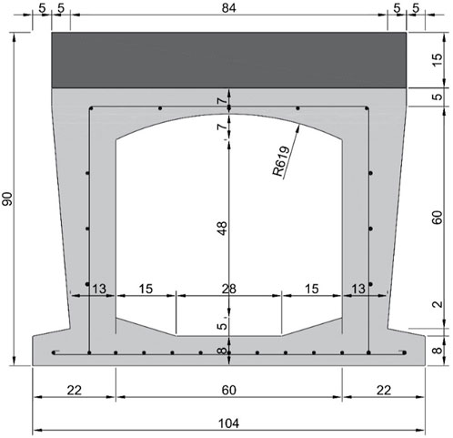
FIGURE 1. Mid-span section dimensions and strengthening details of the test beam (units: cm).
Carbonization depths of the test beams was found to be 0.5 mm–1.0 mm by the appearance and material property inspection of the original RC hollow slab beams. Multiple transverse cracks were present in the bottom plate of the test beam, with a small number of diagonal and vertical cracks on the web. The maximum crack length was 0.5 m, with a maximum width of 0.15 mm. Local concrete protection had peeled off, exposing and corroding rebar, bridge deck paving showed deformation, and expansion joints had failed due to blockage. Moreover, diseases such as inter-slab seepage and leakage were also observed. The load-bearing capacity and working performance of the bridge structure seriously deteriorated under the influence of these diseases. Thus, the technical condition of the bridges was assessed at level 4.
To explore the flexural performance and crack distribution of RC hollow slab beam bottom plate strengthened with UHPC under load, four test beams were designed. Among them, one bare beam received no strengthening and served as the control group. The remaining three beams were strengthened with UHPC, all with a strengthening thickness of 5 cm. The numbering and influencing parameter settings of the test beams are shown in Table 1. To enhance the flexural performance of the UHPC-RC composite beams, the steel mesh was embedded into the UHPC layer. Details of the steel mesh, planting rebar size, and interface treatment are presented in Figure 2. The interface between UHPC and RC was treated by chiseling, planting rebars and a combination of both, respectively. Chiseling was done by means of manual chiseling, while planting rebars was done by locating the holes and subsequently fixing the rebars using a planting adhesive. In this case, the interface planting rebars are “L” type rebars and arranged in a plum blossom pattern. The spacing of each row of rebars was 330 mm. The implantation depth on the RC side was 6.5 cm, and on the UHPC side, it was 2.5 cm.
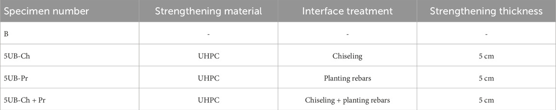
TABLE 1. Impact parameters of the test beams.
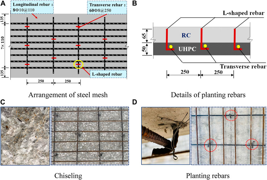
FIGURE 2. Details of steel mesh, planting rebars and interface treatment in test beams (units: mm).
Notes:
(1) Explanation of specimen numbering: “B” represents the unstrengthened beam, “5”represents the thickness of the UHPC strengthening layer, “U” stands for strengthening using UHPC, “Ch” indicates that the interface treatment method is chiseling, and “Pr” signifies that the interface treatment method is planting rebars.
(2) Specifically, chiseling was carried out using a hand-held percussion drill to randomly and irregularly chisel the surface of the RC hollow slab bottom plate, with the roughness of the chiseled specimens maintained in the range of 2–3 mm. The outcome of the chiseling process is illustrated in Figure 2C.
Given that the test beam has been in service for 15 years, it is extremely difficult to directly strip regular standard specimens from the original girder bridge. Thus, after the flexural test was completed, considering factors such as the geometric dimensions of the test beam, the arrangement of rebar positions and maximum aggregate, the method of core drilling was used to sample from the web of the test beam at the beam end. Then, according to the “Standard for test methods of concrete physical and mechanical properties” (GB/T 50081–2019), material testing was conducted on the concrete. An overview of the material properties test of NC is shown in Figure 3A. The results of the mechanical properties are shown in Table 2.

FIGURE 3. Mechanical properties test.

TABLE 2. Measured values of concrete material properties.
As the strengthening layer material, UHPC was a self-developed early-strength dry mix developed by the team. Rapid early strength development was observed, with an initial setting time of 6 h and a final setting time of 14 h. Compressive strength exceeding 70 MPa at 3 days and surpassing 120 MPa at 7 days was achieved. The slump value reached 850 mm, and a self-compacting performance rating of SF3 was attained, obviating the need for steam curing. The mix proportions of UHPC are shown in Table 3. Among them, the steel fiber in UHPC is 11 mm in length and 0.18 mm in diameter. It has a tensile strength of 2,870 MPa and a modulus of elasticity of 200 GPa. The mechanical properties of UHPC were determined according to the “ Reactive powder concrete” (GB/T 31387–2015), standard. During the pouring of the UHPC strengthening layer, the compressive strength was obtained by six cubic specimens with dimensions of 100 × 100 × 100 mm for UHPC (Figure 3B). Six prism specimens with dimensions of 100 × 100 × 300 mm for UHPC was fabricated to obtain the axial compressive strength elastic modulus. Meanwhile, six dog-bone-shaped UHPC specimens were reserved for testing its tensile strength. The measured mechanical properties of UHPC are shown in Table 4.

TABLE 3. Mix proportions of UHPC.

TABLE 4. Mechanical properties of UHPC.
After the concrete in RC hollow slab beam cracked, the concrete quit working. At this point the tensile force in the cracked region of the RC hollow slab beam was mainly carried by the steel rebars. Therefore, the analysis of the structural performance of the flexural zone after cracking was closely related to the constitutive relationship of the steel rebars. Two types of steel rebars were used for RC hollow slab beams, namely, HRB300 and HRB335. After the four-point bending test and concrete specimen sampling were completed, the concrete in the bottom slab of the unstrengthened hollow slab beams was chiseled away. Taking into account the structural load characteristics, steel corrosion conditions and concrete cover conditions, steel specimens were selectively extracted from the least stressed locations at the ends of the beams for tensile testing.
The HRB400 hot-rolled ribbed steel rebars was used for UHPC strengthening layer of the test beams. The interface planting rebars were 8 mm in diameter. The transverse and longitudinal rebars in UHPC layer steel mesh were 8 mm and 10 mm in diameter, respectively. The mechanical properties of the steel rebars were tested in accordance with the standard “ Metallic materials - Tensile testing - Part 1: Method of test at room temperature” (GB/T 228.1–2010). The mechanical performance indicators of the rebars are presented in Table 5.
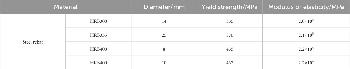
TABLE 5. Mechanical property indicators of steel rebar.
The entire fabrication process of the test beams is depicted in detail as shown in Figure 4. Firstly, as shown in Figure 4A, the test beam bottom plate was carefully levelled and dusted to ensure that the UHPC and RC interfaces were tighter and better bonded together. This was extremely important step, as a tight interfacial bond would substantially increase the durability and bearing capacity of the test beams. Subsequently, holes were drilled to locate the strengthened areas according to the predefined strengthening design scheme, as shown in Figures 4B, C. Next, the interface was treated as in Figure 4D, including chiseling, planting rebars, and a combination of chiseling and planting rebars. In this way, the bond between UHPC and RC was enhanced to further improve the strength and stability of the test beams.
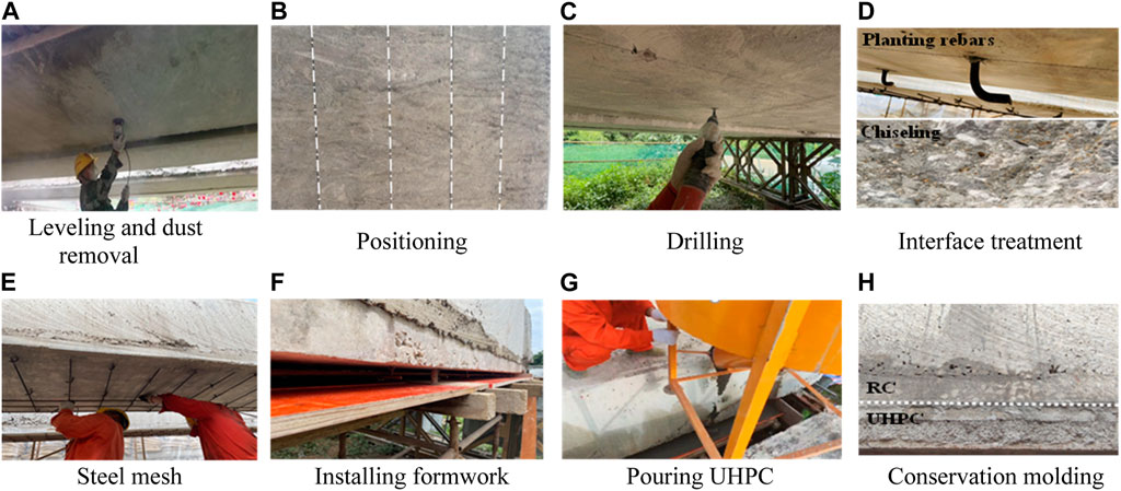
FIGURE 4. Fabrication process of UHPC-RC test beams.
After the above steps were completed, the erection of the steel mesh for the strengthening layer was installed as a means of providing additional support. Formwork was then installed to determine the thickness of the strengthening layer, as shown in Figures 4E, F. Finally, the pouring of the UHPC was carried out and the process and results are shown in Figures 4G, H. After the UHPC-RC combination test beams have been naturally maintained for a period of time, the four-point bending test can be carried out.
The specific details of the experimental loading setup are illustrated in Figure 5. The experimental loading system primarily consists of anchor piles, a loading crossbeam, and hydraulic jacks, among other components. To facilitate the deformation measurement of the test beam, and adequately consider the space of the experimental equipment, concrete bearing platforms were designed at both ends of the beam. Rubber supports were placed between the top of the platform and the bottom of the test beam to simulate the effect of simple beam support.
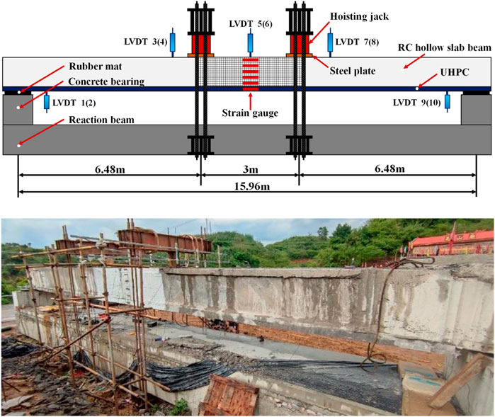
FIGURE 5. Loading device and measurement point arrangement.
The test beam was subjected to four-point bending loading, with two hydraulic jacks synchronized for incremental loading. To verify the proper functioning of the relevant measuring instruments and ensure good contact between different parts of the specimen, the test beam was initially subjected to preloading. Additionally, to ensure that the test beam experienced elastic loading, preventing cracking and any form of residual loading, the preloading load was approximately 20% of the ultimate load (Pu). After completing the preloading and unloading, formal loading of the test beam commenced. The formal loading was divided into two stages: i) The first stage involved force loading, with an approximate load increment of 40 kN for each level. Each level was held for 5 min to observe and record the test behavior. Loading proceeded to the next level once the readings stabilized. ii) The second stage was displacement loading, which was employed when the specimen exhibited significant cracks or reached approximately 60%Pu. Loading was discontinued if the concrete in the compression zone of the test beam fractured, crushed, or if debonding occurred at the interface between UHPC and RC.
The arrangement of measurement points on the test beam is shown in Figure 5. i) Deflection measurements: A total of 10 linear variable differential transformers (LVDTs) were installed, located at the mid-span, at the loading point, and at the section corresponding to the beam end supports. The LVDTs were placed in a symmetrical manner along the span direction. Among these, LVDT displacement sensors with a 50 cm range were used for measurements at the mid-span and the two loading points, while LVDT displacement sensors with a 5 cm range were employed at the support points. ii) Strain measurements: In the vertical direction of the beam, 5 strain measurement points were evenly distributed along the height at the mid-span section of the precast RC hollow slab beam. Additionally, one strain measurement point was positioned at the center of the UHPC strengthening layer, resulting in a total of 6 strain measurement points. During the entire loading process, data from strain gauges and displacement sensors were recorded automatically. Simultaneously, the complete failure process of the specimen was documented using a camera.
To precisely measure crack width, crack distribution and strain conditions during the loading process, the concrete hinge joints on the side of the hollow slab beam were initially removed by chiseling. Subsequently, the pure bending segment (3 m) of the test beams was coated with white paint, a 10 cm × 10 cm grid was drawn. The crack observation instrument and marker pen were used to meticulously measure and record the positions, widths, and heights of cracks for each load level step.
The failure mode and crack distribution of the unstrengthened beam B) are illustrated in Figure 6. When loaded to 80 kN, microcracks appeared on the bottom surface of the mid-span section, with a crack width of 0.143 mm. Upon reaching 160 kN, multiple microcracks developed on the bottom surface, and microcracks at the mid-span section extended horizontally across the bottom plate. At this point, the maximum crack width on the bottom plate reached 0.211 mm, indicating the beam had reached its serviceability limit state. As the load increased to 240 kN, the bottom plate cracks gradually propagated upward along the web, with the maximum bottom plate crack width reaching 0.374 mm and the web’s maximum crack width reaching 0.407 mm. With further load increments, the web cracks continued to propagate upward, both in width and in quantity. When the load reached 400 kN, the maximum crack width reached 1.073 mm. As the load increased to 560 kN, the primary crack at the bottom plate mid-span rapidly expanded and extended diagonally towards the web, forming multiple diagonal cracks with a maximum width of 1.886 mm. Upon reaching the yield load of 620 kN, the web cracks branched out in a dendritic pattern, gradually extending to the top plate of the test beam. The load increase slowed down, and at this point, the maximum crack width reached 2.13 mm. When the load reached the ultimate load of 680 kN, concrete spalling occurred at the mid-span of the bottom plate, exposing the reinforcement, and the test beam lost its load-bearing capacity. The compressed zone concrete remained uncracked.
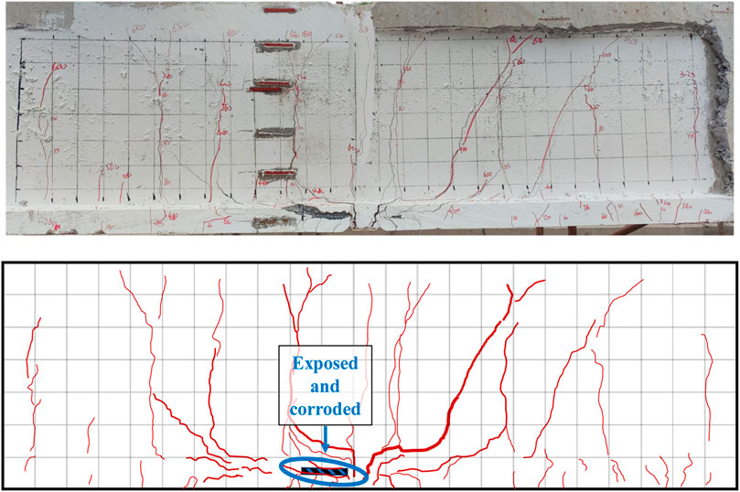
FIGURE 6. The failure mode of B beam.
Compared to the B beam, the bottom plate of the 5UB-Ch beam was strengthened using 5 cm of UHPC, with chiseling treatment applied at the interface. After strengthening with UHPC, the flexural stiffness of the hollow slab beam increased. When loaded to 200 kN, a crack of 0.069 mm was found in the bottom plate of the mid-span section. When the load reached 240 kN, multiple micro-cracks appeared in the bottom plate and UHPC layer, with the maximum crack width being 0.167 mm. At the load of 480 kN, the cracks in the bottom plate extended to the web. The maximum crack widths in the bottom plate and UHPC layer were 0.194 mm, whereas, in the web, it measured up to 0.209 mm. At this point, the 5UB-Ch beam had reached its serviceability limit state.
As the load continued to increase, several vertical cracks appeared on the web, gradually extending to the top plate. The number and width of the cracks in the bottom plate increased, while evenly distributed micro-cracks developed in the UHPC layer. When the load reached the yield load of 720 kN, the maximum crack widths in the web and the bottom plate were 1.528 mm and 0.306 mm, respectively. Upon loading to 800 kN, the crack width in the bottom plate’s mid-span section dramatically increased and quickly evolved into two main cracks, with the maximum crack width becoming 2.185 mm. When the load reached 840 kN, the structure lost its load-bearing capacity. No delamination was observed at the UHPC layer and RC interface. The failure mode and crack distribution of the 5UB-Ch beam are shown in Figure 7.
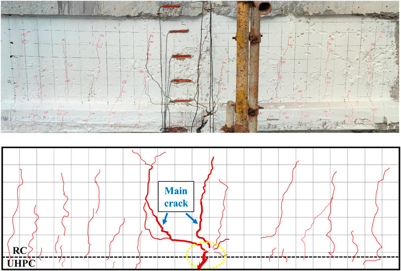
FIGURE 7. The failure mode of 5UB-Ch beam.
The failure mode and crack distribution of the 5UB-Pr beam are shown in Figure 8. The 5UB-Pr beams had the same strengthening parameters as the 5UB-Ch beams, except that the interface treatment was planting rebars. Upon loading to 240 kN, three micro-cracks were observed in the bottom plate with a maximum crack width of 0.097 mm. When the load was increased to 320 kN, the number of cracks in the bottom plate grew and gradually extended to the web. Also some cracks were observed in the UHPC layer with a maximum crack width of 0.167 mm. At a load of 480 kN, the 5UB-Pr beam reached its serviceability limit state, with the maximum crack width of 0.203 mm.
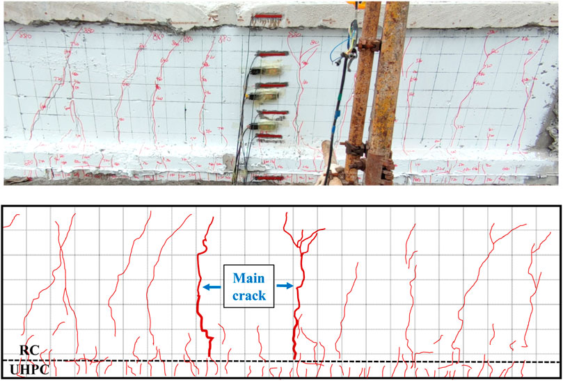
FIGURE 8. The failure mode of 5UB-Pr beam.
As the load continued to increase, numerous evenly distributed minute cracks appeared in the UHPC layer, and several vertical cracks formed on the web and extended towards the top plate. When the load reached the yield load of 760 kN, the vertical cracks in the web developed in a tree-branch manner, extending upwards to the top of the test beam, with a maximum crack width of 0.986 mm. When the load reached 920 kN, the tension reinforcement of the 5UB-Pr beam yielded, and the structure lost its load-bearing capacity. However, the UHPC layer remained well-adhered to the RC beam, with no signs of separation.
Figure 9 illustrates the failure mode of the 5UB-Ch + Pr beam under bending load. In the initial stage of loading, no cracks were visible on the surface of the test beam. Upon loading to 240 kN, three minor cracks appeared at the base of the hollow slab beam, with a maximum crack width of 0.083 mm. When the load reached 360 kN, the micro-cracks in the bottom plate of the hollow slab beam gradually extended upwards, and a few minor cracks emerged in the UHPC layer. At this point, the maximum crack widths were 0.111 mm in the web, 0.162 mm in the bottom plate. Upon loading to 600 kN, the cracks in the web continued to extend upwards, with maximum crack widths of 0.218 mm in the bottom plate, 0.181 mm in the web, and 0.132 mm in the UHPC layer. The 5UB-Ch + Pr test beam had reached its serviceability limit state.
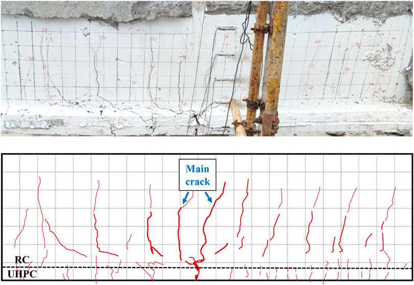
FIGURE 9. The failure mode of 5UB-Ch + Pr beam.
As the load continued to increase, several vertical cracks developed on the web and extended gradually towards the top of the test beam in a tree-branch pattern. The number and width of the cracks in the bottom plate increased, while numerous evenly distributed micro-cracks appeared in the UHPC layer. Upon reaching the yield load of 820 kN, the maximum crack width was 0.958 mm for the web and 1.106 mm for the bottom plate, and the web cracks had developed to the top of the hollow slab beam. When the load reached 940 kN, the structure lost its load-bearing capacity. At this point, the UHPC layer was well-adhered to the bottom plate of the RC beam, with no signs of delamination detected.
The actual mid-span deflection of the test beam before and after strengthening was calculated based on the mid-span vertical displacement and support settlement. The load-deflection curve for the mid-span section of the unstrengthened beam and UHPC strengthened beams are shown in Figure 10. From Figure 10, it was evident that the failure process of the test beam under four-point bending was divided into four stages: i) Elastic stage: Initially, the behavior of the test beam was similar to that of a homogeneous elastic body. The mid-span deflection increased linearly with the increasing load. The load was shared by the tensioned concrete, tensioned steel rebar, and the UHPC strengthening layer. ii) Cracked working stage: After a decrease in the slope of the load-displacement curve, it stabilized. During this stage, cracks appeared on the bottom plate of the test beam and the UHPC strengthening layer. Some of the concrete in the tension zone stopped working and the stiffness of the member was decreased. The load was mainly supported by the tensioned steel rebar and the UHPC strengthening layer until the steel rebar yielded. iii) Strengthening stage: The load-displacement curve exhibited a nonlinear behavior, with the curvature accelerating with increasing deflection. As the tensioned steel rebar yielded, the load was primarily supported by the strengthening material UHPC and the steel mesh within the strengthening layer. iv) Failure stage: The UHPC layer strengthening failed and the stiffness of the test beams decreased significantly. The member lost its load-bearing capacity, and the load decreases as the deflection increased. The points of transition between these four stages (curve inflection points) are the cracking load (Pcr), yield load (Py), and ultimate load (Pu) of the test beam.
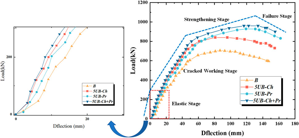
FIGURE 10. Load-displacement curves for mid-span sections.
Throughout the loading process, the mid-span deflection of all four beams increased in response to the increasing load. It was evident that under equivalent load levels, significantly reduced mid-span deflection was exhibited by the UHPC-strengthened beam compared to the unstrengthened beam B). The effectiveness of UHPC strengthening in controlling the mid-span deflection of hollow slab beams has been confirmed by this observation.
Due to the existence of pre-existing cracks in the in-service hollow slab beams, their cracking behavior is characterized by the appearance of new cracks and the extension of existing ones. Figure 11 displays various load-bearing indicators of the test beams, revealing different effects on the load-bearing capacity of the beams under various interface treatment methods. Compared with the unstrengthened beam, the performance of UHPC-strengthened beams was noticeable improved. These improvements in three different stages of loading were observed: cracking load, yield load, and ultimate load. The cracking load of UHPC-strengthened beams increased by 43%–71% as compared to the unstrengthened beam. Similarly, the yield load increased by 19%–32%, and the ultimate load increased by 29%–38%. Comparing and analyzing the load-bearing indicators of the four test beams, the interface treatment method has the most significant effect on the enhancement of the cracking resistance of the UHPC-strengthened beams. The enhancement occurred primarily due to two factors. The first factor was that larger moments of inertia were obtained by increasing the cross-section height. The second factor was that the strengthened beams were subjected to greater tensile stresses before cracking due to the high tensile strength of the UHPC. This phenomenon demonstrated the strengthening and toughening effect of UHPC.
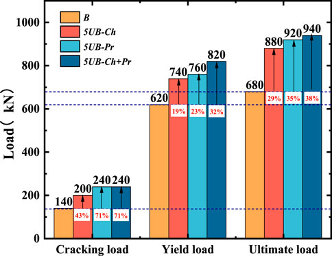
FIGURE 11. Bearing capacity index of test beams with different interface treatments.
The load-bearing capacity of 5UB-Ch + Pr beam was significantly increased as compared to 5UB-Ch and 5UB-Pr beams. The cracking load, yield load and ultimate load of 5UB-Ch + Pr beam were increased by 71%, 32% and 38%, respectively, compared to B beam. The formation of frictional interlocking at the UHPC-RC interface was facilitated by chiseling treatment, thereby enhancing the bond strength. Planting rebars provides an effective “bridging effect” for the interface through dowel action and drawing action. When there are small cracks in the material, the fibers act as a bridge, connecting the two sides of the crack, thus preventing the crack from progressing. Additionally, when the bottom of the test beam (in the tensile zone) was strengthened with UHPC, the concrete substrate was placed in the compressive zone. The full potential of the tensile strength of UHPC and the compressive strength of concrete can be utilized with this flexural load. It helps to seal existing cracks at the bottom of the concrete, increasing the durability of the beams. The magnitude of improvement in load capacity by UHPC strengthening with different interface treatments was compared in Table 6.
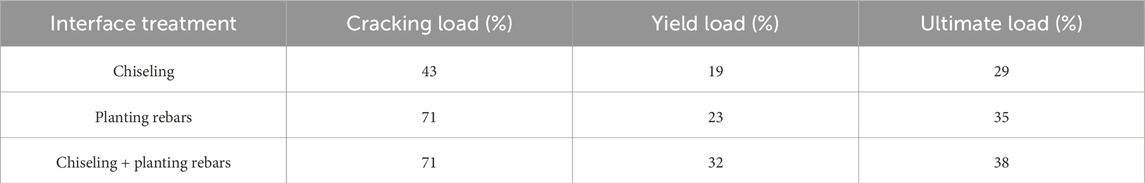
TABLE 6. The magnitude of improvement in load capacity with different interface treatments.
Figure 12 presents the variation curve of the main crack width of the test beams under four-point bending. According to the “Specifications for Design of Highway Reinforced Concrete and Prestressed Concrete Bridges and Culverts” (JTG 3362–2018), the maximum allowable crack width for RC structures is limited to 0.2 mm. Under this crack width limitation, the load-bearing capacity of the unstrengthened beam was 160 kN. For the 5UB-Ch beam with chiseling treatment, the load capacity was 360 kN, which was increased 1.25 times in load-bearing capacity. The 5UB-Pr beam with interface treatment of planting rebars had a load of 480 kN, which was increased 2 times in load carrying capacity. The 5UB-Ch + Pr beam with interface treatment of planting rebars had a load of 560 kN, which was increased 2.5 times. Results showed that in case of smaller crack width, higher load-bearing capacity of UHPC strengthened beams was obtained as compared to unstrengthened beams. Additionally, at the same applied load, the crack widths of 5UB-Pr and 5UB-Ch + Pr beams were reduced compared to 5UB-Ch beam. The change in crack width became more evident as the load value increased. In comparison to 5UB-Ro beam, crack suppression was found to be more significant in 5UB-Pr and 5UB-Ro + Pr beams.

FIGURE 12. Test beam load-maximum crack width curve.
In this study, the flexural stiffness of the test beams is defined by the slopes of the curves in three loading stages: the pre-cracking stage stiffness (Kcr), the pre-yield stage stiffness (Ky), and the pre-failure stage stiffness (Ku). Additionally, the displacement ductility coefficient is employed to assess the ductility performance of the test beams. This coefficient represents the ratio of the vertical displacement at the midspan under the yield load to the vertical displacement at the midspan under the ultimate load.
Figure 13 presents the stiffness and ductility coefficients of the test beams at different loading stages. It can be observed that the stiffness was highest in the pre-cracking stage. Compared to the B beam, the stiffness of the 5UB-Ch beam, 5UB-Pr beam, and 5UB-Ch + Pr beam increased by 50%, 41%, and 65%, respectively, in this stage. However, UHPC contributes significantly to the stiffness improvement of hollow slab beam in the failure stage. The stiffness of 5UB-Ch beam, 5UB-Pr beam, and 5UB-Ch + Pr beam increased by 91%, 49%, and 94%, respectively, compared to the B beam. The interface treatment methods have minimal impact on the stiffness of the test beams in the pre-yield stage. Additionally, using UHPC for strengthening significantly improved the ductility of the test beams. The ductility coefficients of 5UB-Ch beam, 5UB-Pr beam, and 5UB-Ch + Pr beam increased by 8%, 36%, and 44%, respectively, compared to the unstrengthened beam.
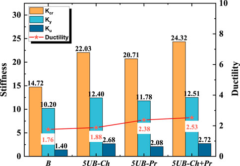
FIGURE 13. Stiffness and ductility coefficients of test beams with different interface treatments.
In addition, the stiffness of the 5UB-Ch beam is 6.4%, 5.2%, and 28.8% higher than that of the 5UB-Pr beam in the respective stages. However, the ductility index of the 5UB-Ch beam is lower than that of the 5UB-Pr beam. These results indicate that chiseling is more favorable for enhancing structural stiffness, while planting rebars is more advantageous for improving structural ductility. The effect of UHPC strengthening on stiffness and ductility with different interface treatments was compared in Table 7.
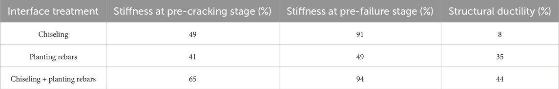
TABLE 7. The magnitude of improvement in stiffness and ductility with different interface treatments.
The following conclusions can be drawn from this research:
■ The failure mode of the unstrengthened beam was characterized by concrete spalling in the tension zone and exposed of steel rebars. In contrast, the UHPC-strengthened beam exhibited a flexural failure mode. Throughout the loading process, the interface between the UHPC and the bottom plate of the RC hollow slab beam was well bonded and no peeling occurred. Uniformly distributed, dense and subtle cracks appeared in the UHPC strengthened layer. Vertical cracks with dendritic development extending to the top slab appeared in the web, and the crack width of the web cracks was larger than the cracks in the UHPC layer.
■ Under different interface treatment methods, UHPC-RC beams exhibited various degrees of improvement in flexural load-carrying capacity. Compared to the unstrengthened beam, the cracking load of 5UB-Ch beam increased by 43%, 5UB-Pr beam by 71%, and 5UB-Ch + Pr beam by 71%. The yield load increased by 19% for 5UB-Ch, 23% for 5UB-Pr, and 32% for 5UB-Ch + Pr. The ultimate load increased by 29% for 5UB-Ch, 35% for 5UB-Pr, and 38% for 5UB-Ch + Pr.
■ The concrete substrate was in the compression zone when UHPC was used to strengthen the service hollow slab beams in the tensile zone. This gave full potential to the super strong tensile strength of the UHPC and the compressive strength of the concrete, resulting in good crack control.
■ The interface bond strength between the UHPC layer and the RC layer was strengthened by using three interfacial treatments: chiseling, planting rebars, and a combination of the two. Crack development in the test beams was effectively inhibited by a combination of chiseling and planting rebars. This measure allowed the interface to have an effective “bridging effect”, providing the structure with a higher bearing capacity reserve.
■ Compared to the unstrengthened beams, the stiffness of UHPC-RC beams increased by 41%–65% and 49%–94% in the pre-cracking and pre-failure stages, respectively. During the pre-failure stage, UHPC played a significant role in increasing the stiffness, whereas a slight decrease in stiffness is observed during the pre-yield stage. At the same time, after UHPC strengthening, the structural ductility increased by 8%–44%.
To comprehensively assess the performance of structural strengthening, it is necessary to conduct further experimental and numerical analyses beyond the variables studied thus far. These additional analyses will explore the impact of critical parameters such as surface roughness, the depth of planting rebar, and the thickness of strengthening layers. Furthermore, environmental factors that can erode or age the strengthening must be taken into account. This requires in-depth scientific research to investigate these durability factors, ultimately ensuring the enduring effectiveness of the strengthening.
The original contributions presented in the study are included in the article/Supplementary material, further inquiries can be directed to the corresponding author.
JS: Investigation, Writing–original draft. BL: Writing–review and editing. LK: Supervision, Writing–original draft. DQ: Investigation, Writing–original draft. CZ: Investigation, Writing–original draft. YK: Data curation, Writing–original draft. AS: Investigation, Writing–original draft.
The author(s) declare financial support was received for the research, authorship, and/or publication of this article. The authors highly appreciate the financial support from the Science and Technology Plan Projects of Chongzuo, China (Grant No. 2022ZC1206 and 2022ZC1217).
Authors JS and BL were employed by Guangxi Transportation Science and Technology Group Co., Ltd. Author CZ was employed by ChongQing Municipal Design and Research Institute Co., Ltd. Author AS was employed by ChongQing City Transportation Development & Investment Group Co., Ltd.
The remaining authors declare that the research was conducted in the absence of any commercial or financial relationships that could be construed as a potential conflict of interest.
All claims expressed in this article are solely those of the authors and do not necessarily represent those of their affiliated organizations, or those of the publisher, the editors and the reviewers. Any product that may be evaluated in this article, or claim that may be made by its manufacturer, is not guaranteed or endorsed by the publisher.
Amran, M., Huang, S. S., Onaizi, A. M., Makul, N., Abdelgader, H. S., and Ozbakkaloglu, T. (2022). Recent trends in ultra-high performance concrete (UHPC): current status, challenges, and future prospects. Constr. Build. Mater. 352, 129029. doi:10.1016/j.conbuildmat.2022.129029
Ciampa, E., Ceroni, F., De Angelis, A., and Pecce, M. R. (2023). Bond tests on concrete elements externally bonded with steel plates and assessment of bond strength models. Eng. Struct. 296, 116835. doi:10.1016/j.engstruct.2023.116835
Du, J., Meng, W., Khayat, K. H., Bao, Y., Guo, P., Lyu, Z., et al. (2021). New development of ultra-high-performance concrete (UHPC). Compos. Part B Eng. 224, 109220. doi:10.1016/j.compositesb.2021.109220
Feng, S., Xiao, H., and Li, H. (2020). Comparative studies of the effect of ultrahigh-performance concrete and normal concrete as repair materials on interfacial bond properties and microstructure. Eng. Struct. 222, 111122. doi:10.1016/j.engstruct.2020.111122
Hou, L., Zhou, B., Guo, S., Aslani, F., and Chen, D. (2019). Corrosion behavior and flexural performance of reinforced concrete/ultrahigh toughness cementitious composite (RC/UHTCC) beams under sustained loading and shrinkage cracking. Constr. Build. Mater. 198, 278–287. doi:10.1016/j.conbuildmat.2018.11.237
Huang, Y., Grünewald, S., Schlangen, E., and Luković, M. (2022). Strengthening of concrete structures with ultra high performance fiber reinforced concrete (UHPFRC): a critical review. Constr. Build. Mater. 336, 127398. doi:10.1016/j.conbuildmat.2022.127398
Leng, J., Yang, J., Zhang, Z., Zou, Y., Chen, J., and Zhou, J. (2023). Experimental and numerical investigations on force transfer mechanism of steel-concrete joint in hybrid girder bridges. Structures 54, 153–170. doi:10.1016/j.istruc.2023.04.104
Li, J., Wu, Z., Shi, C., Yuan, Q., and Zhang, Z. (2020). Durability of ultra-high performance concrete – a review. Constr. Build. Mater. 255, 119296. doi:10.1016/j.conbuildmat.2020.119296
Li, S., Zhang, L., Guo, P., Zhang, P., Wang, C., Sun, W., et al. (2021). Characteristic analysis of acoustic emission monitoring parameters for crack propagation in UHPC-NC composite beam under bending test. Constr. Build. Mater. 278, 122401. doi:10.1016/j.conbuildmat.2021.122401
Li, X., Wu, G., Shafiq Popal, M., and Jiang, J. (2018). Experimental and numerical study of hollow core slabs strengthened with mounted steel bars and prestressed steel wire ropes. Constr. Build. Mater. 188, 456–469. doi:10.1016/j.conbuildmat.2018.08.073
Prem, P. R., Murthy, A. R., and Verma, M. (2018). Theoretical modelling and acoustic emission monitoring of RC beams strengthened with UHPC. Constr. Build. Mater. 158, 670–682. doi:10.1016/j.conbuildmat.2017.10.063
Ren, J., Zhang, K., Xu, X., Xiao, Y., Ye, W., Deng, S., et al. (2023). Performance evolution of self-compacting concrete for ballastless track based on high-cycle fatigue damage constitutive model. J. Cent. South Univ. 30 (6), 2048–2063. doi:10.1007/s11771-023-5348-y
Tong, T., Yuan, S., Wang, J., and Liu, Z. (2021). The role of bond strength in structural behaviors of UHPC-NC composite beams: experimental investigation and finite element modeling. Compos. Struct. 255, 112914. doi:10.1016/j.compstruct.2020.112914
Xue, J., Briseghella, B., Huang, F., Nuti, C., Tabatabai, H., and Chen, B. (2020). Review of ultra-high performance concrete and its application in bridge engineering. Constr. Build. Mater. 260, 119844. doi:10.1016/j.conbuildmat.2020.119844
Xun, S., Shiping, Y., Yuhou, Y., Jian, F., and Litao, L. (2022). Comparative analysis of flexural performance of old full-scale hollow slab beams reinforced with fiber composites. Constr. Build. Mater. 338, 127657. doi:10.1016/j.conbuildmat.2022.127657
Yang, J., Chen, R., Zhang, Z., Zou, Y., Zhou, J., and Xia, J. (2023). Experimental study on the ultimate bearing capacity of damaged RC arches strengthened with ultra-high performance concrete. Eng. Struct. 279, 115611. doi:10.1016/j.engstruct.2023.115611
Yang, J., Xia, J., Zhang, Z., Zou, Y., Wang, Z., and Zhou, J. (2022). Experimental and numerical investigations on the mechanical behavior of reinforced concrete arches strengthened with UHPC subjected to asymmetric load. Structures 39, 1158–1175. doi:10.1016/j.istruc.2022.03.087
Zhang, Y., Huang, S., Zhu, Y., Hussein, H. H., and Shao, X. (2022). Experimental validation of damaged reinforced concrete beam strengthened by pretensioned prestressed ultra-high-performance concrete layer. Eng. Struct. 260, 114251. doi:10.1016/j.engstruct.2022.114251
Zhang, Z., Jin, X., and Luo, W. (2019). Long-term behaviors of concrete under low-concentration sulfate attack subjected to natural variation of environmental climate conditions. Cem. Concr. Res. 116, 217–230. doi:10.1016/j.cemconres.2018.11.017
Zhang, Z., Pang, K., Xu, L., Zou, Y., Yang, J., and Wang, C. (2023). The bond properties between UHPC and stone under different interface treatment methods. Constr. Build. Mater. 365, 130092. doi:10.1016/j.conbuildmat.2022.130092
Zhou, G., Du, A., Wang, M., Fan, J., and Li, A. (2023). Performance degradation prediction of extra-wide concrete self-anchored suspension bridge under vehicle load considering time-dependent effects. J. Cent. South Univ. 30 (6), 1932–1947. doi:10.1007/s11771-023-5360-2
Zhu, Y., Zhang, Y., Hussein, H. H., and Chen, G. (2020). Flexural strengthening of reinforced concrete beams or slabs using ultra-high performance concrete (UHPC): a state of the art review. Eng. Struct. 205, 110035. doi:10.1016/j.engstruct.2019.110035
Zhu, Y., Zhang, Y., Li, X., and Chen, G. (2021). Finite element model to predict structural response of predamaged RC beams reinforced by toughness-improved UHPC under unloading status. Eng. Struct. 235, 112019. doi:10.1016/j.engstruct.2021.112019
Zou, Y., Jiang, J., Yang, J., Zhang, Z., and Guo, J. (2023a). Enhancing the toughness of bonding interface in steel-UHPC composite structure through fiber bridging. Cem. Concr. Compos. 137, 104947. doi:10.1016/j.cemconcomp.2023.104947
Keywords: bridge engineering, UHPC strengthening, hollow slab beam, flexural capacity, interface treatment
Citation: Song J, Li B, Kong L, Qin D, Zhu C, Kuang Y and Shan A (2024) Effect of interface treatment on the flexural performance of existing RC bridge beams strengthened with UHPC. Front. Mater. 11:1361647. doi: 10.3389/fmats.2024.1361647
Received: 26 December 2023; Accepted: 24 January 2024;
Published: 08 February 2024.
Edited by:
Zhongya Zhang, Chongqing Jiaotong University, ChinaReviewed by:
Yangxi Zhang, Xi’an University of Architecture and Technology, ChinaCopyright © 2024 Song, Li, Kong, Qin, Zhu, Kuang and Shan. This is an open-access article distributed under the terms of the Creative Commons Attribution License (CC BY). The use, distribution or reproduction in other forums is permitted, provided the original author(s) and the copyright owner(s) are credited and that the original publication in this journal is cited, in accordance with accepted academic practice. No use, distribution or reproduction is permitted which does not comply with these terms.
*Correspondence: Baojun Li, amFtYmVybHkyQDE2My5jb20=
Disclaimer: All claims expressed in this article are solely those of the authors and do not necessarily represent those of their affiliated organizations, or those of the publisher, the editors and the reviewers. Any product that may be evaluated in this article or claim that may be made by its manufacturer is not guaranteed or endorsed by the publisher.
Research integrity at Frontiers
Learn more about the work of our research integrity team to safeguard the quality of each article we publish.