
94% of researchers rate our articles as excellent or good
Learn more about the work of our research integrity team to safeguard the quality of each article we publish.
Find out more
ORIGINAL RESEARCH article
Front. Mater. , 29 January 2024
Sec. Structural Materials
Volume 11 - 2024 | https://doi.org/10.3389/fmats.2024.1308290
 Nguyen Minh Tuan1,2,3Nguyen Van Toan1Vu Thang Long3
 Luong Van Duong1
 Pham Van Trinh1,2Tran Bao Trung1,2Doan Dinh Phuong1,2*
Herein, we investigated the effect of W content on the jet penetration performance of W-Cu shaped charge liners by using both simulation and experimental methods. The W-Cu composite liners were prepared directly by using spark plasma sintering (SPS) technique. Microstructural observations showed that W particles were uniformly dispersed within the Cu matrix. The relative density of W-Cu composites decreased slightly from 99.2% to 98.8% with an increase in the W content. The hardness of the W-Cu composite liner increased as increasing W content and reached the highest value of 209.2 HV for the composite reinforced by 60 wt.% W. Besides, the penetration depth increased and reached the maximum value of 80 mm for the composite liner containing 50 wt.% W which is improved by about 11% compared to pure Cu liner. According to simulation and experiment results, the penetration depth of the W-Cu composite liners exhibits a nearly identical trend. W-Cu composite liner containing 50 wt.% W remains the best performance compared to other composites. However, the experimental results are lower compared to the simulation results. This could be because the simulation procedure did not completely account for the actual test conditions.
Shaped charges are the explosive devices that concentrate the energy of a convex explosive block, deform the liners and apply it to the convex surface of the explosive block, forming a metal jet and then moving at extremely high speeds to penetrate steel, concrete, and stone… (Ma et al., 2016; Ma et al., 2022). Shaped charges are used in many industrial fields such as oil and gas exploitation, transportation, mining and defense sectors (Wang et al., 2019; Yi et al., 2019; Baykara et al., 2021; Sun et al., 2021; He et al., 2022; Jiang et al., 2022). A typically shaped charge consists of four main components: (1) the liner, (2) the explosive, (3) the shell, and (4) the detonator. In particular, the liners have many different shapes, depending on the purpose such as: conical (for penetrating steel), spherical (for making wide holes), or funnel-shaped (for creating pipes). Many different materials have been tested for liners (Xu et al., 2019; Sun et al., 2023). However, copper (Cu) was the first material to be used due to its high density and good ductility deformation (W. B. Li et al., 2015). Using a liner made of gold (Au) could obtain a penetration up to 47% deeper than that of the Cu liner as testing on the same target materials. However, the cost of an Au liner is much higher than that of a bronze liner. Metals with face-centered cubic (FCC) crystal structures have better plastic deformation ability than those with body-centered cubic (BCC) crystal structures (Feng et al., 1996). Therefore, the metals such as tungsten (W), and tantalum (Ta) are not selected as liner materials because of their poor plastic deformation ability. Copper is still widely used as liner material in almost studies related to shaped charge (Ahmed and Qadeer Malik, 2017). Liu et al. (2017) combined simulation and experiment to study the structural change and thermodynamic parameters of the metal jet formed from the Cu liner. Park studied the change in the structure of the liner fabricated by Ta before and after penetrating the steel (Park et al., 2019). In addition, aluminum (Al), Titanium (Ti), Zirconium (Zr), Uranium (U), and Silver (Ag). were also mentioned as metals that have been studied and tested for liners of the shaped charges (Elshenawy and Li, 2013; Saran et al., 2013; Wang et al., 2014) used Ni and Mo metals as the shaped charge materials and concluded that the penetration of the Mo liner is deeper than that of the Cu and Ni liner by 10.0% and 21.3%, respectively (Xu et al., 2019).
In addition to pure metals, many studies have also focused on the development of alloys for liners. The W-Cu-Ni alloy was studied by He and Jia (2010), while Lee (2002) used Cu-20%Pb alloy for the liner material of the shaped charges used in the oil and gas industry. Sun et al. studied two types of alloys including Ni-Al and Cu-Ni-Al used liners for shaped charges and found that Cu-Ni-Al alloy has 42% greater penetration depth than Ni-Al alloy Sun et al. (2018), Cui et al. (2020) studied the Zr-based amorphous alloy as a liner material. The study has shown the optimal focal length for the amorphous Zr alloy material but also shows that the Zr base amorphous alloy has a smaller penetration depth than copper (Cui et al., 2020). The penetration depth of the shaped charges depends on the density of the liner and the jet length. Therefore, to increase the penetration depth, it is necessary to increase the density while maintaining the high plastic deformation capacity of the material. Materials with a high density such as Mo, W or Zr have high density but low plastic deformation ability, whereas materials such as Al, Sn have good plastic deformation capacity but low density, so they hardly improve the penetration depth. Subsequent studies focused on using Cu matrix composites reinforced by high-density materials such as W, Mo. to increase the density and at the same time maintain the good ductility of the Cu matrix. Studies using Cu-W or Cu-Mo composite liner were conducted in the late 90s of the 20th centuries (Li et al., 2015; Ahmed and Qadeer Malik, 2017). It is well-known that, W-Cu is classified as a “pseudo alloy” because the W and Cu components do not form a solution or intermetallic compounds. W-Cu composites provide excellent thermal, electrical, and mechanical performance due to their integrated properties of high hardness and strength, a low thermal expansion coefficient, good arc resistance from W, and high electrical and thermal conductivity from Cu. This class of materials is widely used in civilian industrial fields such as high-voltage electric contact parts, welding electrodes, electronic packaging, and thermal sinks, and it is also in high demand in the aerospace industry (Zhang et al., 2023). Specially, W-Cu alloy has enormous potential in the area of shaped charge liner materials due to its high density, high velocity, and high ductility (Wang et al., 2021; Zhuo et al., 2022). Some research groups investigated the jet velocity of W-Cu and Cu liners and found that the tip velocity of the W-Cu jet was significantly higher than that of the Cu jet (Seok-Hwan, 2005; Zhang et al., 2010; Ibrahim et al., 2014; Wang et al., 2014; Guo et al., 2016; Wang et al., 2022; Chen et al., 2023; Li et al., 2024). During the jet penetration process, there was a large adiabatic temperature rise at the impact site of the W–Cu jet under ultra-high pressure, resulting in the melting of the Cu phase. The melted Cu flowed around the W particles and formed a Cu-rich layer between the jet and the target, and the Cu-rich layer played an important role in insulating the jet and the target (Zhang et al., 2010). The W phase with a high melting point moved easily in the melted Cu phase and made a major contribution to the penetration depth. Wang et al., fabricated Cu-W composite liner (80Cu-20W) with a small amount of nickel (0.5%) and observed that the penetration depth increased by 30% as a result of the higher density of the composite liner compared to the Cu liner (Wang and Zhu, 1996). Similarly, Zygmunt and Wilk fabricated Cu-W composite liner using electrolytic Cu powder (Zygmunt and Wilk, 2008). The study showed that, although the jet velocity was lower, the penetration depth was still greater due to the increased liner density (12.5 g/cm3). In another study conducted by Elshenawy, Cu-W composite cones were fabricated by the pressing technique from Cu-W powder mixture and compared with Cu liner (Elshenawy et al., 2018). This study also shows that the penetration depth is larger than when using a Cu liner (Elshenawy et al., 2018). Zhao et al. (2016) reported that the addition of Zn and Ni to the W–Cu composite liner will reduce the penetration depth but increase the penetration area on the target. In addition, Zhao suggested that the addition of Zn will lead to an increase in the interface bond strength between the W particles and the Cu matrix (Zhao et al., 2016; Yan et al., 2020) fabricated a multi-layer composite liner from W-Ta and W-TiN-Ta materials and showed that the mechanical properties of the liner have been significantly improved. In addition, the shaped charge test also demonstrated that this composite has a high potential for making liners of shaped charge devices (Yan et al., 2020). General, up to now, Cu-W composite is still being used for fabricating the metal liners of the shaped charge devices due to the increase in penetration depth. Most of the studies mainly focused on improving the penetration depth through the optimization of the structure and the properties of the liner material. In generally, W-Cu composites could be prepared by using powder metallurgy (PM) technology. It is usually required to have a high sintering temperature and a long holding time in order to achieve the required level of densification (Zhang et al., 2023). Thus, the grain coarsening is unavoidable, and copper may leach out of the skeleton, which causes copper segregation, which in turn causes a non-homogenous microstructure and poor product performance. The most common approach used in the fabrication of W-Cu composites is known as melt infiltration. However, this technique remains some defects such as pores, copper lakes, and tungsten agglomerates, resulting in a low-quality product. Because of the significant differences in melting points, densities, and mutual solubility, W-Cu composites with ultra-fine grain are extremely challenging to fabricate. In this context, many novel technologies have been explored to enhance the properties of W-Cu composites, including, laser sintering, plasma spraying and specially spark plasma sintering, etc. (Zhang et al., 2023). Generally, SPS was used to prepare the cylinder-shaped samples for additional characterization. However, conical liners with internal apex angles ranging from 40° to 90° are the most common shape. To the best of our knowledge, no research has been done so far on the use of the SPS technique to prepare W-Cu composite in a conical shape for microstructure and performance analysis.
Therefore, this study aims to prepare directly the full density, fine grain and high performance of W-Cu composite with a conical shape for the first time by using SPS technique. The conical shaped W-Cu composites were used for shaped charge liner and tested the penetration performance on 40Cr steel target. The influence of W contents on the performance of the W-Cu composite liner by using both simulation and experimental methods. The simulation study was performed by using Ansys AutoDyn -2D software. The microstructure, hardness, and performance of the W-Cu composite liner were investigated and presented.
A commercial Cu powder with a dendritic shape supplied by Xilong Scientific Co., Ltd., has a purity of 99.5% and a particle size in the range of 44–74 µm (Figure 1A). The W powder with an angular shape has a purity of 99.9% and an average particle size of 50 µm (Figure 1B).
FIGURE 1. SEM images of (A) Cu powder and (B) W powder.
The conical W-Cu composite liners with different W contents were fabricated by the powder metallurgy method (Table 1). First, W and Cu powders with the designed weight ratio along with 1% paraffin added as a binder and 10% n-hexane medium were mixed and milled using high energy ball (HEB) milling technique. The powder was thoroughly mixed and milled for 48 h with a speed of 250 rpm using W-Co hard alloy balls with a ratio of balls/powder is 2/1 to obtain W-Cu composite powder. After that, the obtained powder was taken out and dried in a vacuum oven. The obtained W-Cu composite powders were pressed in a conical mold (Figures 2A, B) at a pressing pressure of 6 MPa following mixing. After pressing and shaping, the billet undergoes a pre-sintering process at a temperature of 930°C for 120 min in a hydrogen atmosphere to obtained the required strength before the SPS sintering stage. After pre-sintering, samples were cleansed and placed in graphite molds for SPS sintering using the SPS Labox 350 system (Sinterland, Japan). The SPS sintering procedure was conducted at 900°C for 15 min at a pressure of 32.36 MPa under a vacuum condition of 6 Pa (Figure 2C) to obtain the W-Cu liner specimen (Figure 2D).
TABLE 1. Composition and theoretical density of the W-Cu composites with different W contents.
FIGURE 2. Structure and photograph of the conical W-Cu composite liners. (A) Structure of liner, (B) graphite molds, (C) SPS sintering cycle and (D) liner specimen.
To study the structure of the cone material, the sample is taken from the center position of the liner by wire cutting method as shown in Figure 3. Then the sample was ground, impregnated with FeCl3 solution (5 g) + HCl (10 mL) + H2O (100 mL). The microstructure of the materials was studied using optical microscopes (Axiovert 40 MAT, Germany), scanning electron microscope (SEM, Hitachi S4800, Japan), and transmission electron microscope HR-TEM (JEOL JEM) 2100, Japan). The energy dispersive X-ray spectroscopy (EDS, Hitachi S4800, Japan) was used to analyze the composition of the composites. X-Ray diffraction (XRD) patterns of the samples were recorded by using Bruker D8 Advance X-Ray diffractometer.
FIGURE 3. Observation site for the microstructure analysis of prepared samples.
The density of the samples was measured by the Archimedes method on the Japanese AND GR-202 instrument by Formula 1:
where γ is the density of sample (g/cm3), mair and mwater are the mass of the samples measured in air and water, respectively.
A microhardness tester (IndentaMet 1106, Buehler United States) was used to determine the microhardness of the samples. Five measurements of the samples were taken at various points on the sample surface to evaluate the accurate hardness results. The value of hardness is the average value of 5 measurements with an error of 2%.
To evaluate the penetration ability of the samples, a test system was set up as shown in Figure 4. The explosive device consists of a steel body, a W-Cu liner and 38 ± 1 g of H11 explosive. Steel target made of 40Cr steel (C = 0.38%–0.44%, Cr = 0.8%–1.1%) has a diameter of 80 mm and a thickness of 120 mm. The distance from the bottom surface of the liners to the top surface of the steel target is 22 mm. The steel target and the explosive device are fixed by the screw behind the steel target, ensuring that the explosive quantity and the steel target cannot be moved during the preparation test. When detonated, the explosive block will create a shock wave, deforming the W-Cu liner into a solid stream of metal, moving through the steel target at high speed and then creating a hole. After each explosion, the steel target is taken out, and cut in half lengthwise at the center of the hole to observe and measure the penetration depth. The reported penetration depth is the average value of the two measurements.
FIGURE 4. The schematic of the test system for the shaped charge.
The simulation process was performed by using Ansys AutoDyn -2D software. AUTODYN is an analysis module based on the finite element method integrated into ANSYS Workbench, specialized for solving nonlinear dynamics problems for solid, flow, or gas models. In this study, the shaped charge has a structure consisting of three main elements including shell, explosive, and liner. The penetration depth (P) of the shaped charge will depend on the jet length formed after the explosive reaction occurs and the density of the liner according to Formula 2:
Where L is the jet length, ρj is the density of the liner, ρt is the density of the target material, and λ is the coefficient related to the jet length with a value in the range from 1 to 2. The P will depend on the jet length L. In this simulation, the structure of the liner, shape charge, and steel target are shown in Figure 5. The structure of the shape charge has 03 main elements: shell (1); explosives (2), and liner (3). The shell is cylindrical, designed from 40Cr steel with an outer diameter D, and length L. The explosive block A-IX-1 has a cylindrical shape. The design dimensions for the liners and shell are presented in Table 2. The composition of the liners with specific density values according to theoretical calculations used in the simulation is shown in Table 1 and Table 3.

TABLE 2. Dimensions of the liner, shaped charge, and steel target.
TABLE 3. Some properties of Cu were used in the simulation process.
FIGURE 5. The schematic view of the liner, shaped charge, and steel target used in the simulation: 1- Shell; 2- Block of explosives; 3- Liner; 4- Detonator; 5- Steel target.
The simulation output will give the results of the jet length (L), the penetration depth (P) on 40Cr steel, and the jet velocity (υ1). A-IX-1 an explosive with similar properties to H11 explosive was used for the simulation process. The A-IX-1 has a composition (93.5–95)% RDX and (4–6.5)% tamed, with a density in the range of 1.6–1.68 g/cm3 and the explosion speed was determined to be 7,500–8,000 m/s. As for the Cu liner, the simulation results show that the υ1 achieved before hitting the target was determined at about 6,357 m/s with, the L of 43 mm and the P of 80 mm. When simulating the Cu-W composite liners with different W content, the effect of liner density on the formation of the jet length and the maximum penetration depth on the steel target was evaluated. Figure 6 shows the jet velocity of the W-Cu composite liner with different W contents. The obtained results indicated that the jet velocity of W-Cu composite liners was decreased with the increase of W content. With Cu70W30 composite, the jet velocity was calculated to be 6,288 m/s. When increasing the W content up to 60%, the jet velocity is only 5,446 m/s which is decreased by 14.3% compared to pure Cu liner.
FIGURE 6. The jet velocity of W-Cu composite liner with different W contents.
Figure 7 shows the simulation results of the W-Cu composite liner with different W contents. Figure 8 shows the dependence of the jet length and the penetration depth of the W-Cu composite liners. The jet length of the liners tends to decrease from 43 to 40 mm when increasing W content from 0% to 60%, increasing the penetration depth. The penetration depth of the liners increased from 80 to 95 mm when increasing the W content from 0% to 50%. However, when continuously increasing the W content up to 60%, the penetration depth of the liner decreases rapidly to 85 mm, which is about 10.5% reduction compared to the composite containing 50% W content. From the simulation results, it is shown that increasing the W content will increase the density of the liners but decrease the jet velocity. The penetration depth tends to increase with increasing W content from 0% to 50% and then rapidly decreases when W content increases up to 60%. From Eq. 2, it is shown that the penetration depth depends on the jet length and the density of the liners. However, the penetration depth significantly decreased when the W content increased to 60%. This demonstrated that, in addition to the dependence on the density of the liners and the jet length generated after the explosive reaction, the penetration depth may also depend on the jet velocity. The previous computational simulation studies also indicated the dependence of the penetration depth on the distance between the shaped charge and the target (H), the density of the liner (ρj), target density (ρt), the jet tip velocity (νtip), the jet velocity(νj) as seen in Eq. 3 with x = ρj/ρt and the α is the coordinate that can be calculated by numerical simulation (Guo et al., 2019).
FIGURE 7. Simulation results on the jet length (L) and the penetration depth (P) of the W-Cu composite liners with different W contents (A,B) Cu, (C,D) Cu70W30, (E,F) Cu60W40, (G,H) Cu50W50 and (I,J) Cu60W40.
FIGURE 8. (A) The jet length and (B) the penetration depth of the W-Cu composite liners.
The maximum penetration depth of the shaped charge was achieved with a W content of 50 wt.% according to the simulation results, possibly due to the optimization between the increase in the density and the jet velocity. The jet velocity decreases with the increase in the density of the liners. As the W content increases from 0 to 50 wt.%, the jet velocity is slightly decreased. However, the jet velocity reduced significantly with the liner containing W content up to 60 wt.%, which caused a reduction in the penetration depth. As a result, the W-Cu composite liner containing 50 wt.% W content remains the largest penetration depth.
To validate the simulation results, the W-Cu composite liners containing different W contents were fabricated by SPS. Figure 9 shows the morphological images of W-Cu powder after milling. As can be seen, W and Cu powders were uniformly dispersed together and Cu powders were deformed during the milling process. The Cu powders were much deformed and become significantly compared to their initial shapes. In contrary, W seem still remain their initial shape. This is attributed that Cu is much softer than that of W.
FIGURE 9. SEM images of W-Cu composite powder containing 50 wt.% W after milling (A,B) low magnification and high magnification and EDS spectrum at related points.
Figure 10 shows the SEM images of pure Cu and W-Cu composite containing different W contents after SPS sintering. As can be observed, the microstructure of pure Cu is uniform with gray color. In contrary, with W-Cu composite, the presence of W particles (white) was observed. These W particles were fairly uniform dispersed within the Cu matrix (gray). To confirm the composition of the samples, EDS mapping and EDS spectra of W-Cu composite containing 50 wt.% W content were measured. As shown in Figure 11, the gray zone exhibited a rich Cu element (red color) and the white zone is a rich W element (blue color). EDS points also confirmed the conclusion, the composition at point A (white color) and point B (red color) are W and Cu elements, respectively.
FIGURE 10. SEM images of W-Cu composite liners with different W contents (A) pure Cu, (B) Cu70W30, (C) Cu60W40, (D) Cu50W50 and (E) Cu60W40.
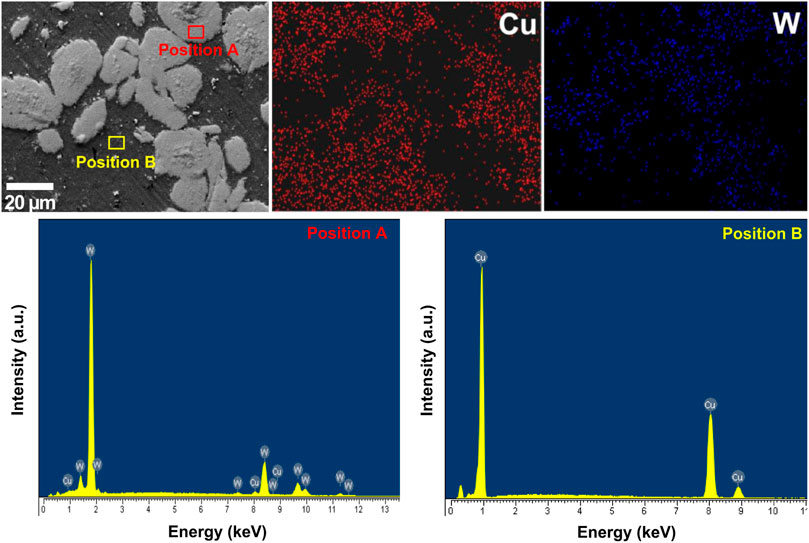
FIGURE 11. SEM image, EDS mapping and EDS spectra of W-Cu composite containing 50 wt.% W content.
Figure 12 shows the chemical composition of the W-Cu composite liners. As a result, the samples contain Cu and W for W-Cu composite and Cu for pure Cu with concentrations as shown in the table associated with the figures. There is a slight difference between the Cu and W contents as designed. In addition, a small amount of oxygen with content <1 wt.% can also be analyzed. This is unavoidable due to the amount of oxygen that can be present on the surface of Cu and W particles during the powders and liners fabrication. However, with a low oxygen content of less than 1%, it can also be considered that the sintering process does not cause oxidation for W-Cu composite liners. Figure 13 shows the XRD patterns of the W-Cu composite liners. The obtained results indicated that typical peaks of Cu and W were detected for W-Cu composite and only typical Cu peaks were detected for pure Cu. The typical peaks of Cu were determined at 2θ of 43.8°, 50.9° and 74.4° corresponding to (111), (200) and (220) planes, respectively (JCPDS No. 003–1018). The typical peaks of W are located at 2θ of 40.3°, 58.2° and 73.2° corresponding to (110), (200) and (211) planes, respectively (JCPDS No. 04–0806). Besides, a small oxidation phase of Cu was also detected at 2θ of 32.51°, 36.1° and 48.7° corresponding to (110), (11-1) and (20-2) planes, respectively (JCPDS No. 48–1548). The obtained results are good agreement with EDS analysis with small amount of detected oxygen.
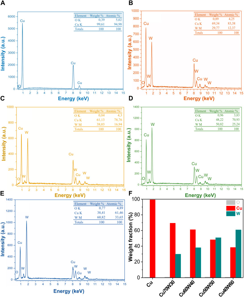
FIGURE 12. EDS spectra of the W-Cu composite containing different W contents (A) pure Cu, (B) Cu70W30, (C) Cu60W40, (D) Cu50W50, (E) Cu60W40 and (F) the composition of the prepared samples.
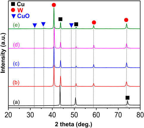
FIGURE 13. The XRD patterns of the W-Cu composite containing different W contents (A) pure Cu, (B) Cu70W30, (C) Cu60W40, (D) Cu50W50, (E) and Cu60W40.
Figure 14A shows the density and relative density of W-Cu composite liners containing different W contents. As a result, the density of the W- Cu composites increased with increasing W content, from 8.89 to 12.76 g/cm3 corresponding to W content from 0 to 60 wt.%. Compared with the theoretical density, the measured density of the composites is lower. The obtained results showed that when increasing the W content from 0% to 50%, the relative density of the composites decreases slightly from 99.2% to 98.8%. However, the relative density decreased significantly to 96.7% for the composite containing 60 wt.% W content. This indicated that the increase of the W content may cause the formation of W clusters. These clusters inhibited the densification process due to generated pores among W particles. These pores cannot be filled by Cu matrix during the sintering process, resulting in decreasing the relative density of composite. Besides, this may also result from the low wettability of Cu and W (Gu and Shen, 2008; Ibrahim et al., 2014; Elsayed et al., 2015). Figure 14B shows the Vickers hardness of W-Cu composite liners containing different W contents. For the pure Cu liner, the hardness was measured to be 73.8 HV. When increasing the W content, the hardness of the W-Cu composite increases rapidly, the hardness reached 126.3 HV for the composite contained 30 wt.% W and reached the highest value of 209.2 HV for the composite reinforced by 60 wt.% W. This could be explained as follow: in W-Cu composite system, W acted as reinforcement materials and Cu acted as matrix. The increase in the hardness of the composites with the addition of W could result from W acted as the keys hindered the movements of dislocations. Furthermore, the mismatch strains may develop at the W-Cu interfaces resulted from the difference of the coefficients of thermal expansion between W and the Cu matrix. The mismatch strains will block the movement of the dislocations to enhance the hardness of the composites.
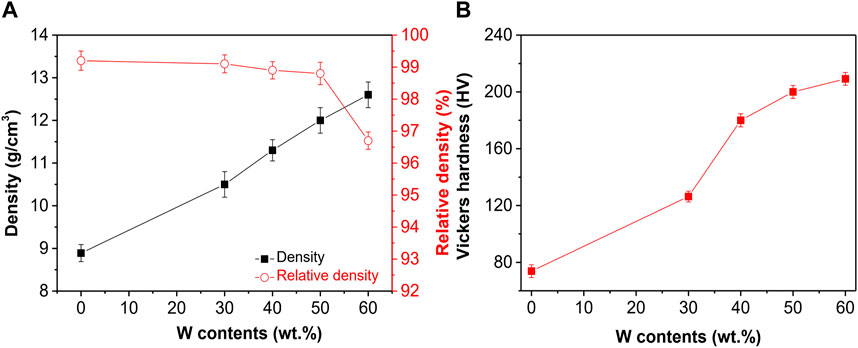
FIGURE 14. (A) Density and relative density and (B) Vickers hardness of W-Cu composite liners containing different W contents.
The prepared W-Cu composite liners were introduced to the shape charge test. The tests were carried out under the same test conditions including the same explosive type, explosive mass and 40Cr steel target to compare the penetration depth of the prepared composite liners. Figure 15 shows the optical image of cross-section along the penetration depth on a 40Cr steel target after testing. Figure 16 shows the comparison of the penetration depth between the simulation and experimental results of the W-Cu composite liners with different W contents. The obtained results indicated that the penetration depth increases and reaches the maximum value P of 80 mm for the composite liner containing 50 wt.% W content. After that, the penetration depth decreased to 64 mm as increasing W content up to 60 wt.%. The decrease in the penetration depth of composite containing 60 wt.% is mainly attributed to the decrease in the relative density. The decrease in the relative density of W-Cu composite implied that the pores were formed with in the composite during the preparation process. It is interesting to note that the trend of the penetration depth of the W-Cu composite liners is nearly the same between the experimental and simulation results. However, the experimental results are lower than those of the simulation results. This could be due to the actual test conditions not being fully considered in the simulation process. For example, the samples were prepared by SPS remaining relative density less than 100%, but the simulation process taken into account the sample with full density (100% relative density). Therefore, the addition material processing after SPS such as spinning or rolling techniques could be a key point for preparing full density composites and thus obtain a good match between the experimental and simulation results.
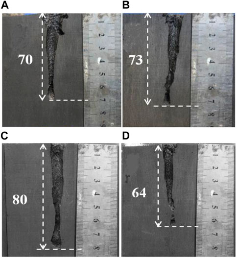
FIGURE 15. Cross section along the penetration depth on a 40Cr steel target after testing of (A) Cu70W30, (B) Cu60W40, (C) Cu50W50 and (D) Cu60W40.
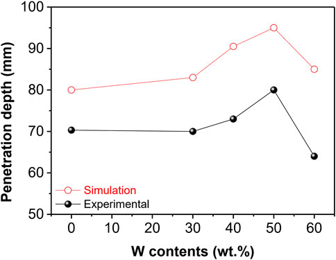
FIGURE 16. Comparison of the penetration depth between the simulation and experimental results of the W-Cu composite liners with different W contents.
We have investigated the effect of W contents on the penetration depth of the W-Cu composite shaped charge liners. The W-Cu composite liners were prepared by SPS technique with W particles uniformly distributed in the Cu matrix. The relative density of the W-Cu composites decreased with increasing W content, from 99.2% to 96.7%. The hardness of W-Cu composite liners increases with increasing W content and reached to 209.2 HV for a composite reinforced with 60 wt.% W. The liner containing 50 wt.% W content exhibited the best performance in the penetration against 40Cr steel compared to other composites. The penetration depth increased by roughly 11% compared to a pure Cu liner and reached a maximum of 80 mm. The obtained results have a significant impact on the field of materials science, especially about W-Cu composites and their applications in shaped charge technology.
The raw data supporting the conclusion of this article will be made available by the authors, without undue reservation.
NT: Formal Analysis, Investigation, Methodology, Validation, Writing–original draft. NV: Formal Analysis, Investigation, Writing–original draft. VL: Investigation, Writing–original draft. LD: Formal Analysis, Investigation, Validation, Writing–original draft. PV: Conceptualization, Writing–original draft, Writing–review and editing. TT: Conceptualization, Supervision, Writing–original draft. DD: Conceptualization, Supervision, Writing–original draft, Writing–review and editing.
The author(s) declare that no financial support was received for the research, authorship, and/or publication of this article.
The authors declare that the research was conducted in the absence of any commercial or financial relationships that could be construed as a potential conflict of interest.
All claims expressed in this article are solely those of the authors and do not necessarily represent those of their affiliated organizations, or those of the publisher, the editors and the reviewers. Any product that may be evaluated in this article, or claim that may be made by its manufacturer, is not guaranteed or endorsed by the publisher.
Ahmed, M., and Qadeer Malik, A. (2017). A review of works on shaped charges. Eng. Technol. Appl. Sci. Res. 7 (5), 2098–2103. doi:10.48084/ETASR.1532
Baykara, T., Günay, V., and Demirural, A. (2021). Structural evolution and microstructural features of the hydrodynamically penetrating copper jet of a shaped charge. J. Mater. Eng. Perform. 30 (3), 1862–1871. doi:10.1007/s11665-021-05514-9
Chen, P., Xu, D., Huang, C., Yang, J., Tai, Y., Hong, T., et al. (2023). Multi-factor coupled failure mechanism of W–Cu functionally graded material under thermal shock service. J. Mater. Res. Technol. 27, 5082–5092. doi:10.1016/J.JMRT.2023.10.317
Cui, P., Wang, D., Shi, D., Gao, X., Xu, J., and Zhen, J. (2020). Investigation of penetration performance of Zr-based amorphous alloy liner compared with copper. Materials 13 (4), 912. doi:10.3390/MA13040912
Elsayed, A., Li, W., El Kady, O. A., Daoush, W. M., Olevsky, E. A., and German, R. M. (2015). Experimental investigations on the synthesis of W–Cu nanocomposite through spark plasma sintering. J. Alloys Compd. 639, 373–380. doi:10.1016/J.JALLCOM.2015.03.183
Elshenawy, T., Abdo, G., and Elbeih, A. (2018). High penetration performance of powder metallurgy copper-tungsten shaped charge liners. Central Eur. J. Energetic Mater. 15 (4), 610–628. doi:10.22211/CEJEM/100683
Elshenawy, T., and Li, Q. M. (2013). Breakup time of Zirconium shaped charge jet. Propellants, Explos. Pyrotech. 38 (5), 703–708. doi:10.1002/PREP.201200191
Feng, C., Murr, L. E., and Niou, C. S. (1996). Aspects of dynamic recrystallization in shaped charge and explosively formed projectile devices. Metallurgical Mater. Trans. A Phys. Metallurgy Mater. Sci. 27 (7), 1773–1778. doi:10.1007/bf02651926
Gu, D., and Shen, Y. (2008). Influence of Cu-liquid content on densification and microstructure of direct laser sintered submicron W–Cu/micron Cu powder mixture. Mater. Sci. Eng. A 489 (1–2), 169–177. doi:10.1016/J.MSEA.2007.12.008
Guo, H., Zheng, Y., Yu, Q., Ge, C., and Wang, H. (2019). Penetration behavior of reactive liner shaped charge jet impacting thick steel plates. Int. J. Impact Eng. 126, 76–84. doi:10.1016/J.IJIMPENG.2018.12.005
Guo, W., Liu, J., Xiao, Y., Li, S., Zhao, Z., and Cao, J. (2016). Comparison of penetration performance and penetration mechanism of w-cu shaped charge liner against three kinds of target: pure copper, carbon steel and Ti-6Al-4V alloy. Int. J. Refract. Metals Hard Mater. 60, 147–153. doi:10.1016/J.IJRMHM.2016.07.015
He, H., and Jia, S. (2010). Direct electrodeposition of Cu-Ni-W alloys for the liners for shaped charges. J. Mater. Sci. Technol. 26 (5), 429–432. doi:10.1016/S1005-0302(10)60067-9
He, Z., Cheng, Y., He, H., An, C., Huang, Y., Zhang, X., et al. (2022). Jet penetration performance of a shaped charge liner prepared by metal injection molding. Metals 12 (6), 1021. doi:10.3390/MET12061021
Ibrahim, H., Aziz, A., and Rahmat, A. (2014). Enhanced liquid-phase sintering of W–Cu composites by liquid infiltration. Int. J. Refract. Metals Hard Mater. 43, 222–226. doi:10.1016/J.IJRMHM.2013.12.004
Jiang, Y., Gu, R. C., Wang, J. T., Xiao, Q. Q., and Huang, Z. X. (2022). Investigation on the grain size effect on the copper shaped charge jet stretching behavior. Front. Mater. 9, 605. doi:10.3389/fmats.2022.1017629
Lee, W. H. (2002). Oil well perforator design using 2D Eulerian code. Int. J. Impact Eng. 27 (5), 535–559. doi:10.1016/S0734-743X(01)00054-9
Li, W. B., Li, W. B., Wang, X. M., and Zhou, H. (2015). Effect of the liner material on the shape of dual mode penetrators. Combust. Explos. Shock Waves 51 (3), 387–394. doi:10.1134/s0010508215030168
Li, X., Wang, Q., Wei, S., Lou, W., Liang, J., Chen, L., et al. (2024). Microstructure and high-temperature mechanical properties of Cu-W composite prepared by hot isostatic pressing. J. Alloys Compd. 970, 172571. doi:10.1016/J.JALLCOM.2023.172571
Liu, J. F., Long, Y., Ji, C., Xu, D., Xiang, D., and Song, G. (2017). Dynamic response and microstructure evolution of oxygen-free high-conductivity copper liner in explosively formed projectile. Lat. Am. J. Solids Struct. 14 (11), 2089–2106. doi:10.1590/1679-78253958
Ma, B., Huang, Z., Xiang, Z., and Xiao, Q. (2016). Experimental study on external strong magnetic fields coupling with the shaped charge jet. Int. J. Impact Eng. 98, 88–96. doi:10.1016/J.IJIMPENG.2016.08.007
Ma, T. B., Liu, J., and Wang, Q. (2022). Influence of shaped charge structure parameters on the formation of linear explosively formed projectiles. Def. Technol. 18 (10), 1863–1874. doi:10.1016/J.DT.2021.08.005
Park, S. T., Kim, J. Y., Kim, G. L., Kang, H. S., Oh, K. W., Park, H. K., et al. (2019). Study of shape and microstructure changes of Ta linear for building an explosively formed penetrator. J. Korean Inst. Metals Mater. 57 (8), 475–481. doi:10.3365/KJMM.2019.57.8.475
Saran, S., Ayisia, O., and Yavuz, M. S. (2013). Experimental investigations on aluminum shaped charge liners. Procedia Eng. 58, 479–486. doi:10.1016/J.PROENG.2013.05.055
Seok-Hwan, K. Y. M. J. U. Y. S. (2005). “Finite element analysis for die compaction process of W-Cu composite powders for shaped charge liner,” in Proceedings of the Korean powder metallurgy institute conference (Seoul, Korea: The Korean Powder Metallurgy and Materials Institute), 28–29.
Sun, M., Li, C., Zhang, X., Hu, X., Hu, X., and Liu, Y. (2018). Reactivity and penetration performance Ni-Al and Cu-Ni-Al mixtures as shaped charge liner materials. Materials 11 (11), 2267. doi:10.3390/MA11112267
Sun, S., Jiang, J., Wang, S., Men, J., and Li, M. (2023). Structural design of the fluted shaped charge liner using multi-section optimization method. Def. Technol. 25, 249–262. doi:10.1016/J.DT.2023.01.008
Sun, S., Jiang, J., Wang, S., Men, J., Li, M., and Wang, Y. (2021). Comparison of shaped charge jet performance generated by machined and additively manufactured CuSn10 liners. Materials 14 (23), 7149. doi:10.3390/MA14237149
Wang, G., Qin, Y., and Yang, S. (2022). Influence of Ni additions on the microstructure and tensile property of W-Cu composites produced by direct energy deposition. J. Alloys Compd. 899, 163272. doi:10.1016/J.JALLCOM.2021.163272
Wang, H., Guo, H., Geng, B., Yu, Q., and Zheng, Y. (2019). Application of PTFE/Al reactive materials for double-layered liner shaped charge. Materials 12 (17), 2768. doi:10.3390/MA12172768
Wang, T. F., and Zhu, H. R. (1996). Copper-tungsten shaped charge liner and its jet. Propellants, Explos. Pyrotech. 21 (4), 193–195. doi:10.1002/PREP.19960210406
Wang, Y., Zhuo, L., and Yin, E. (2021). Progress, challenges and potentials/trends of tungsten-copper (WCu) composites/pseudo-alloys: fabrication, regulation and application. Int. J. Refract. Metals Hard Mater. 100, 105648. doi:10.1016/J.IJRMHM.2021.105648
Wang, Z., Wang, H., Hou, Z., Xu, H., and Li, Y. (2014). Dynamic consolidation of W-Cu nano-alloy and its performance as liner materials. Rare Metal Mater. Eng. 43 (5), 1051–1055. doi:10.1016/S1875-5372(14)60099-0
Xu, W. L., Wang, C., Yuan, J. M., and Deng, T. (2019). Bore-center annular shaped charges with different liner materials penetrating into steel targets. Def. Technol. 15 (5), 796–801. doi:10.1016/J.DT.2019.07.001
Yan, Z., Xu, G., and Suo, J. (2020). Study on W/(TiN)Ta composite and its application in shape charge liner. SN Appl. Sci. 2 (10), 1736–1739. doi:10.1007/s42452-020-03517-0
Yi, J., Wang, Z., Yin, J., and Zhang, Z. (2019). Simulation study on expansive jet formation characteristics of polymer liner. Materials 12 (5), 744. doi:10.3390/MA12050744
Zhang, B., Yang, K., Huang, Z., and Wang, J. (2023). Recent advances in W–Cu composites: a review on the fabrication, application, property, densification, and strengthening mechanism. Adv. Eng. Mater. 26, 2301204. doi:10.1002/ADEM.202301204
Zhang, X., Wu, C., and Huang, F. (2010). Penetration of shaped charge jets with tungsten-copper and copper liners at the same explosive-to-liner mass ratio into water. Shock Waves 20 (3), 263–267. doi:10.1007/s00193-010-0248-0
Zhao, Z., Liu, J., Guo, W., Li, S., and Wang, G. (2016). Effect of Zn and Ni added in W–Cu alloy on penetration performance and penetration mechanism of shaped charge liner. Int. J. Refract. Metals Hard Mater. 54, 90–97. doi:10.1016/J.IJRMHM.2015.07.022
Zhuo, L., Liu, C., Yin, E., Zhao, Z., and Pang, S. (2022). Low-cost and low-temperature 3D printing for refractory composite inspired by fused deposition modeling and binder jetting. Compos. Part A Appl. Sci. Manuf. 162, 107147. doi:10.1016/J.COMPOSITESA.2022.107147
Keywords: W-Cu composite, penetration depth, shaped charge liner, spark plasma sintering, density, hardness
Citation: Tuan NM, Van Toan N, Long VT, Duong LV, Van Trinh P, Trung TB and Dinh Phuong D (2024) Effect of tungsten contents on the jet penetration performance of shaped charge liner based copper-tungsten composites. Front. Mater. 11:1308290. doi: 10.3389/fmats.2024.1308290
Received: 06 October 2023; Accepted: 15 January 2024;
Published: 29 January 2024.
Edited by:
Zhanyong Zhao, North University of China, ChinaReviewed by:
Donghua Dai, Nanjing University of Aeronautics and Astronautics, ChinaCopyright © 2024 Tuan, Van Toan, Long, Duong, Van Trinh, Trung and Dinh Phuong. This is an open-access article distributed under the terms of the Creative Commons Attribution License (CC BY). The use, distribution or reproduction in other forums is permitted, provided the original author(s) and the copyright owner(s) are credited and that the original publication in this journal is cited, in accordance with accepted academic practice. No use, distribution or reproduction is permitted which does not comply with these terms.
*Correspondence: Doan Dinh Phuong, cGh1b25nZGRAaW1zLnZhc3QuYWMudm4=
Disclaimer: All claims expressed in this article are solely those of the authors and do not necessarily represent those of their affiliated organizations, or those of the publisher, the editors and the reviewers. Any product that may be evaluated in this article or claim that may be made by its manufacturer is not guaranteed or endorsed by the publisher.
Research integrity at Frontiers
Learn more about the work of our research integrity team to safeguard the quality of each article we publish.