 Răzvan Ioan Păcurar1
 Filippo Sanfilippo2*
 Martin Bjaadal Økter2
 Diana-Irinel Băilă3Cătălin Zaharia3Adrian Ionuţ Nicoară3Ionuț Cristian Radu3Tom Savu3Filip Górski4Wiesław Kuczko4
 Radosław Wichniarek4Dan Sorin Comşa1Martin Zelenay5Paweł Woźniak6
- 1Department of Manufacturing Engineering, Faculty of Industrial Engineering, Robotics and Production Management, Technical University of Cluj-Napoca, Cluj-Napoca, Romania
- 2Department of Engineering Sciences, Faculty of Engineering and Science, University of Agder (UiA), Grimstad, Norway
- 3National University of Science and Technology Politehnica Bucharest, Bucharest, Romania
- 4Faculty of Mechanical Engineering, Poznan University of Technology, Poznan, Poland
- 5Bizzcom s r o, Bučany, Slovakia
- 6B3D s c, Poznań, Poland
Advancements in materials science and 3D printing technologies have opened up new avenues for developing low-cost robotic grippers with high-performance capabilities, making them suitable for various biomechatronic applications. In this research, it has been explored the utilization of high-performance polymer materials, such as Polyetherketoneketone (PEKK), Polyethylene Terephthalate Glycol (PET-G) and MED 857 (DraftWhite), in the designing and developing of customized robotic grippers. The primary focus of made analyses was oriented on materials characterization, both experimentally and analytically. Computer-Aided Engineering (CAE) methods were employed to simulate bending experiments, allowing for a comprehensive analysis of the mechanical behavior of the selected materials. These simulations were validated through physical bending experiments using samples fabricated via 3D printing technologies, including Fused Filament Fabrication (FFF) for PET-G and PEKK, as well as Jetted Photopolymer (PolyJet) technology employing UV Resin for MED 857. The findings of this research provided advantages of utilizing advanced materials like PEKK in low-cost robotic grippers for biomechatronic applications. The experimental and analytical approaches offer valuable insights into material selection, design optimization, and the development of cost-effective high-performing robotic systems with a wide range of applications in the field of biomechatronics.
1 Introduction
In recent years, the field of bioengineering has undergone a remarkable transformation, driven by technological advancements in materials science and manufacturing methods (Xiaohu, 2020; Salmi, 2021; Hornyák et al., 2023). The advent of 3D printing technologies has ushered in a new era of innovation in bioengineering (Ding et al., 2023). This category of technology allows for the precise, layer-by-layer fabrication of complex structures, providing unprecedented levels of design flexibility and customization (Chaudhry and Czekanski, 2020; Gawade et al., 2022; Tofail et al., 2018]. From prosthetic limbs to robotic grippers, 3D printing has revolutionized the way people approach the development of biomechatronic devices using such advanced manufacturing methods (Arena et al., 2021; Aylar et al., 2021).
A wide range of materials is nowadays available on the market, each offering particular advantages and disadvantages in the realization of biomechatronic devices (Segil, 2018; Barrera et al., 2022). High-performance FFF (Fused Filament Fabrication) materials, including but not limited to PEKK, has garnered significant attention for their outstanding mechanical properties (Wasti and Adhikari, 2020; Luo et al., 2023; Nguyen et al., 2023). These polymers possess exceptional strength, stiffness, and resistance to heat and chemicals, making them ideal candidates for applications demanding robustness and durability (Pang et al., 2023). High-performance FFF materials outshine their standard Fused Filament Fabrication counterparts, such as PET-G, in terms of mechanical resistance, allowing for the creation of biomechatronic components which are capable of withstanding considerable stress and wear in these conditions (Arleo et al., 2021; Mercado-Colmenero et al., 2020). However, the use of these materials is not without challenges. Precise temperature control is essential during the printing process, and issues like warping can pose difficulties, especially for intricate and large-scale designs (Yang et al., 2017; Winter et al., 2022) Balancing the advantages with the complexities of handling these materials remains a key consideration in the case of biomechatronic applications (Iftekar et al., 2023). The integration of carbon fiber composites into Fused Filament Fabrication (FFF) materials has expanded the scope of possibilities further on in several domains, including biomechatronics. Composites combine the versatility of FFF printing with enhanced mechanical properties, introducing newfound strength and stiffness (Korkees et al., 2020; Mondal et al., 2022; Xiaoyu and Runzhou, 2022). Yet, this enhancement comes at a cost, both in terms of material expenses and the demands placed on the 3D printing equipment (Bai et al., 2021). Finding the right balance between performance and affordability remains an ongoing pursuit for researchers and engineers in the field of biomechatronics (Li et al., 2016). On the other end of the spectrum, PolyJet technology represents one reliable alternative, employing UV resins to produce highly detailed, intricate structures with remarkable precision and smooth surface finishes (Kim et al., 2022; Golhin et al., 2023). This technology excels in creating visually appealing and intricately designed components, a quality particularly important in applications like customized prosthetics (Xu and Qin, 2023). However, the mechanical characteristics of PolyJet materials may not always meet the rigorous demands of biomechatronic devices, where strength and durability are highly important (Patpatiya et al., 2022a). Moreover, the initial and ongoing costs associated with PolyJet technology can be one disadvantage for those seeking cost-effective solutions (Chen et al., 2021; Gülcan et al., 2021).
Biomechatronic devices, including robotic arms place a unique set of demands on the materials used in their construction (Mick et al., 2019). Mechanical characteristics such as flexural strength, tensile properties, compressive and wear resistance are highly important in determining the performance and durability of these applications (Krawczuk and Palacz, 2021; Andersson and Björsell, 2022; Witte, 2022). Robotic arms, for instance, rely heavily on bending and flexing to function effectively, directly influencing their lifting capacity and precision (Kramberger et al., 2017). Consequently, the choice of materials for these devices must be made with thorough consideration of these mechanical characteristics (Coyle et al., 2018). To assess the justifiability of employing high-performance materials like PEKK in the development of customized robotic grippers for biomechatronic applications, the current article aims to provide one comprehensive analytical and experimental approach. Analytical studies, including finite element analysis (FEA) have been utilized to simulate and optimize the mechanical behaviors of the components. Empirical research has been conducted to validate these analytical findings and to assess the performances of the robotic grippers that were taken into consideration in this research. Importantly, within the realized experiments it has been emphasized the critical role of materials characterization methods, such as scanning electron microscopy (SEM), energy-dispersive X-ray spectroscopy (EDX) and Fourier-transform infrared spectroscopy (FTIR) for validating the results reached in the case of mechanical testing experiments and to ensure meantime in particular the suitability of PEKK polymer material for specific applications, such as the robotic grippers. The article aims to provide an analytical and experimental research to provide one comparative analysis realized in the case of using high-performance materials like PEKK against conventional alternatives like PET-G and MED 857 (DraftWhite) materials, so one may comprise and understand both the advantages and challenges in utilizing these materials in the development of low-cost robotic grippers for biomechatronic applications by 3D printing technologies.
2 Materials and methods
2.1 Research concept and plan
The main concept of the presented research was to answer the question if the use of the so-called high-performance 3D printing materials in production of customized robotic arms is justifiable by results of manufacturing processes and material tests. To answer that question, one high-performance material—PEKK—was selected and compared with two other popular materials (PET-G and MED 857 (DraftWhite) and technologies (FFF and Polyjet) by means of both analytical and empirical studies, based on previous knowledge and achievements of the authors.
In the initial phase of the research presented in this article, materials and their samples were characterized by selected test methods (including FTIR-ATR). Then, by using a designed variant of an existing robotic gripper that was developed by part of the team of authors from the University of Agder (Norway) in previous studies (Sanfilippo et al., 2012; 2014; 2015a; 2015b) (Figure 1), parts of it were manufactured using various materials and have been subjected to strength tests emulating loading of a robotic arm. Simultaneously, the tests were performed using Finite Element Analysis, to check and compare analytical and empirical results. Various indicators were assumed to be used in order to compare selected materials and to answer the basic research questions. In this context has been considered the opportunity of considering, testing the mechanical behavior and using of new polymeric materials (like polyetherketoneketone - PEKK) for realizing of customized low-cost robotic grippers for biomechatronic applications. Regarding control algorithms for the proposed manipulator design, more details can be found in the following previously reported work and results (Tuan et al., 2019; 2021; 2022; Sanfilippo et al., 2020; Moosavi et al., 2022).
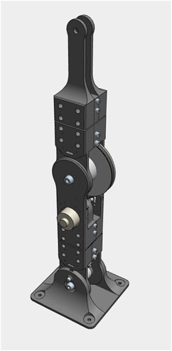
FIGURE 1. Robotic arm designed by UiA in previous studies (Sanfilippo et al., 2012; 2014; 2015a; 2015b).
Figure 2 shows the course of the research including the most important stages. Particular parts of the research are described in the next chapters of the article.
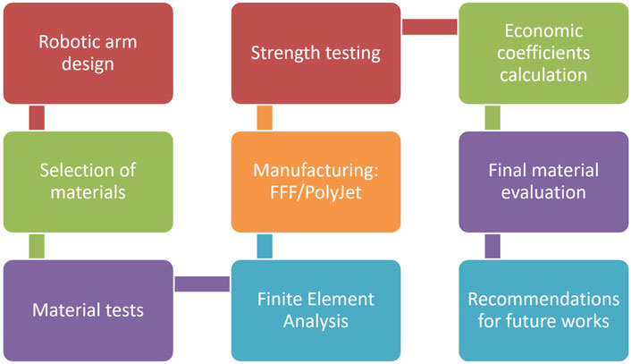
FIGURE 2. Course of the research described in the article.
2.2 Material characterization methodology
2.2.1 FTIR—ATR analysis
In this scientific article, one of the primary objectives consisted in the conducting of a comprehensive FTIR-ATR (Fourier-Transform Infrared Spectroscopy—Attenuated Total Reflectance) to analyze the molecular composition of PEKK (Polyetherketoneketone). The FTIR-ATR spectrum of PEKK was recorded using a state-of-the-art Bruker Vertex 70 FT-IR spectrophotometer combined with an ATR accessory featuring a diamond crystal. This instrument was set to run 32 scans at a resolution of 4 cm-1 in the mid-infrared region of 4,000–600 cm-1. Through this detailed spectral analysis, there have been identified specific functional groups and absorption bands, providing insights into the chemical structure and potential advantages of PEKK over PET-G (Polyethylene Terephthalate Glycol) and DraftWhite (MED 857) materials that have been considered to be used in the experiments. This method allowed the assessment of the material’s chemical composition and structural integrity, highlighting the unique characteristics of PEKK material and its suitability for the realizing of robotic grippers.
2.2.2 EDS and SEM investigation
In the context of this scientific article, a significant component of the research consisted in the use of Energy-Dispersive X-ray Spectroscopy (EDS) combined with Scanning Electron Microscopy (SEM) analyses to determine the elemental composition, chemical homogeneity, and structural characteristics of the PEKK (Polyetherketoneketone) material. EDS was utilized to identify and quantify the elemental constituents of PEKK material, allowing for a comparative analysis with PET-G and MED 857 (DraftWhite) materials that have been considered to be used in the experiments. In addition, SEM analyses provided insights into the microstructure of PEKK material, focusing on surface morphology such as grain size, porosity, and texture, and identifying of any defects or irregularities, with the main aim of highlighting the unique attributes and potential advantages of PEKK material in comparison to the ones of PET-G and MED 857 (DraftWhite) materials. SEM and EDS analyses of the samples were conducted utilizing a QUANTA INSPECT F50 scanning electron microscope equipped with a field emission gun (FE-SEM) from Thermo Fisher, Eindhoven, Netherlands, achieving a fine resolution of 1.2 nm. This was used in combination with a Thermo Fisher energy-dispersive X-ray spectrometer, attaining a resolution of 133 eV at MnK. The analysis has been focused on the top, side, and mid-sections of the PEKK samples for a comprehensive qualitative assessment using microcompositional X-ray spectrometry. Resulting spectra were plotted using ImageJ 1.50i software (Wayne Rasband National Institute of Health, MD, USA, 2016). Prior to the SEM analysis, samples were meticulously cleaned with distilled water and isopropyl alcohol, being then sputter-coated with a conductive ultra-thin gold layer to mitigate the effects of their non-conductive nature.
2.3 Finite element analysis to estimate the mechanical behavior of robot tooltip
The finite element analysis consists in the simulation of a bending test (Figure 3) with the aim of evaluating the strength characteristics of the robotic tooltip in three cases corresponding to different materials used for 3D printing: PET-G filament produced by Spectrum (PET-G. 2023), PEKK filament produced by Kimya (PEKK-A. 2023), and MED857 (DraftWhite) material produced by Stratasys (Stratasys, 2023). As shown in Figure 3, the tooltip components are assembled and placed in a clamping device. The bending effect is then produced by enforcing a vertical displacement of the threaded fastener placed at the free end of the tooltip.

FIGURE 3. Principle of the bending test simulated for evaluating the strength characteristics of the robotic tooltip (1—clamping device, 2—robotic tooltip, 3—screw, 4—washers, 5—nut, red arrow—vertical displacement of the threaded fastener).
The finite element model of the bending test was based on the following hypotheses:
• The components of the robotic tooltip are fully locked in the regions representing contact surfaces with the clamping device.
• The components of the threaded fastener (screw, washers, and nut—see Figure 1) are treated as rigid bodies.
• The components of the robotic tooltip are deformable bodies exhibiting an isotropic linear elastic behavior.
• The physical and mechanical properties of the analyzed materials (PET-G Premium material characteristics datasheet. 2023; PEKK material characteristics datasheet. 2023; MED 857 (DraftWhite) material characteristics datasheet. 2023) for the finite element model of the bending test were:
- density (1,270 [kg/m3] for PET-G, 1,261 [kg/m3] for PEKK and 1,175 [kg/m3] for MED 857 (DraftWhite) material,
- Elastic modulus (1950 [MPa] for PET-G, 2,850 [MPa] for PEKK and 2,200 [MPa] for MED 857 (DraftWhite) material,
- Poisson’s ratio (0.4 [-] for all considered materials,
- Yield stress (48 [MPa] for PET-G, 80 [MPa] for PEKK and 45 [MPa] for MED 857 (DraftWhite) material.
• All the parts shown in Figure 3 were bonded together along their contact surfaces.
SolidWorks Simulation program was used for performing the Computer Aided Engineering (CAE) analyzes. For performing the CAE analyses to simulate the bending test for evaluating the strength characteristics of the robotic tooltip, several crucial details have been addressed to ensure accuracy and reliability of the results, such as:
• choosing of finite elements: For simulating the bending test, second-order tetrahedral elements have been utilized to ensure a high degree of precision in replicating the bending behavior of the robotic tooltip.
• meshing characteristics: the mesh was designed with smaller elements in areas of interest, such as the regions where bending stresses have been concentrated. For example, in the vicinity of potential stress concentrations, like the attachment points of the robotic tooltip, the element size was reduced to 0.5 mm, while in less critical areas it was increased to 1 mm. This approach ensured that the CAE realized analyses capture the finer details of stress distribution and deformation where needed while maintaining computational efficiency calculus being made.
The mesh consisted of 29,798 second-order tetrahedral elements with a total number of 48,949 nodes.
• applied forces: to closely mimic the real-world bending test, the CAE analysis applied forces that were consistent with the experimental results. In the actual experiment, maximal forces recorded were approximately 500 N for PET-G, 1000 N for PEKK, and 1600 N for MED857 (DraftWhite) material. Similarly, in the CAE analyses, these forces were replicated to maintain fidelity with the experimental conditions. This alignment of forces ensured that the CAE results were directly comparable to the physical tests, allowing for a meaningful assessment of the robotic tooltip’s strength characteristics.
2.4 Additive manufacturing methods used for producing and testing of robotic tooltip
To empirically test the difference in using PEKK material for robotic end effector construction as opposed to standard materials such as PET-G and MED 857 (DraftWhite) materials, the end effector was manufactured additively using varying processes and materials. For each manufactured set of parts, 3 aspects were assessed: manufacturing process (stability, assembly fit), economical aspect (manufacturing time and total cost) and strength (maximum force recorded at the bending test). There was no manufacturing parameters variability between samples made of the same material. The products were manufactured using the Fused Filament Fabrication (FFF) technology, with two different materials—PET-G and PEKK, as well as Jetted Photopolymer (PolyJet) technology, using one, standard material MED 857 (DraftWhite) which is an UV resin. Three sets of robotic tooltip pieces were manufactured of each material (a single set consisting of 2 tooltip parts and 2 spacers).
The manufacturing was realized using the following machines and parameter setting:
• FFF technology, PET-G material samples—FLSun Super Racer machine (Zhengzhou Chaokuo Electronic Technology Co., China) with delta type kinematics, with a working chamber sized Ø260 × 330 mm. For printing the samples made of PET-G material, the extrusion temperature of 250°C, table temperature: 70°C, extrusion velocity: 40 mm/s layer thickness: 0,25 mm, infill density: 30%, 4 outlines, 4 bottom/top closing lines were used as main parameters.
• FFF technology, PEKK material samples—Intamsys Funmat Pro 410 (INTAMSYS Technology Co. Ltd, Shanghai, China) with regular kinematics and build chamber sized 305 × 305 × 406 mm. For printing the samples made of PEKK material, the extrusion temperature: of 380°C, table temperature: 130°C, chamber temperature: 90°C, extrusion velocity: 25 mm/s, layer thickness: 0,25 mm, infill density: 30%, 4 outlines, 4 bottom/top closing lines were used as main parameters.
• PolyJet technology—Stratasys MediJet J5 machine (Stratasys Ltd., Minnesota, United States of America), with circular working chamber (max part size up to 140 × 200 × 190 mm) and 18 micron layer thickness.
For all the manufacturing processes, the same manufacturing orientation was used, with the parts laying flat in the build chamber, to generate as few layers as possible.
The PEKK material filament had to be additionally dried prior to manufacturing. The drying process was realized using laboratory drier oven SLW 53 made by POL-EKO company in Poland. The drying, as recommended by the material producer, was realized in 100°C for 10 h and then for an additional 3 h in 150°C. Manufacturing commenced directly after drying, with no cooling period.
For comparison of the different materials and processes, economic coefficients were also determined after printing. Using a standard method of calculating cost of additively manufactured products applied in previous researches by the authors, e.g., in (Górski et al., 2020; Górski et al., 2021), the costs of printouts of different technologies and materials were compared. The following formula was used for cost calculation:
where:
cp—total cost of produced part,
USDcmac—cost of machine usage (taking into account amortization cost - purchase cost per 2 years of continued usage - and electrical energy consumption), USD/h,
tm—time of manufacturing (layer deposition only) [h],
cmat—cost of material, USD/g.
mp—mass of used material [g],
cw—additional work cost, USD (estimated—taking into account pre- and post-processing operations—drying, cleaning etc.)
It is noteworthy that the calculation was realized in a non-commercial manner—only the basic, objectively determined costs were accounted for, not including margin (profit) of potential manufacturer.
2.5 Mechanical testing setup experiments
The strength testing of the manufactured samples consisted of a destructive quasi cantilever beam bending test of the assembled robotic end effector tooltip, manufactured additively of PET-G, PEKK and MED 857 (DraftWhite) materials. The strength tests were performed with the universal strength testing machine Sunpoc WDW-5D-HS (Sunpoc, Guiyang, China). The tooltip was assembled using standard metric nuts and bolts and constrained together at the testing machine rail using additional metal supports. Tooltip ends were also connected with a nut and bolt. The whole tooltip assembly was considered as a single sample in the testing experiments. The machine loading effector was placed in the middle, to simulate loading of the tip. The whole set, immediately before testing, is presented in Figure 4.
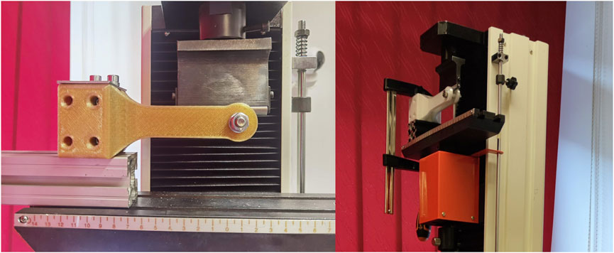
FIGURE 4. Strength testing setup of a PEKK printed sample using universal testing machine.
The result of each test is a course of a load–displacement diagram, obtained from the used strength testing machine. The test was carried out until the sample was destroyed (by cracking) or visibly deformed. Speed of movement of the loading end was 10 mm/min.
To be able to compare obtained results with the FEM analyses, the stress in the main (narrow) part of the tooltip was determined analytically, by using a formula for stress calculation in beams subjected to bending. The experiment was a typical scenario of a cantilever beam—constrained at one end, with force applied at the other, free end. For the sake of the analysis, the geometry was simplified—it was assumed that there is a beam of 70 mm length, with two rectangular cross-sections of 25 × 5 mm, separated with a 12,7 mm space, constrained at one end and loaded at the other end. It was assumed that the cross-section is homogeneously rectangular, with a constant cross-section through the whole beam. The rounded shape of the end part of the gripper was neglected as having small impact on the final results. These assumptions are presented in Figure 5.

FIGURE 5. Loaded part treated as a cantilever beam—assumed dimensions (l = 70 mm, cross section of 25 × 5 mm two times separated by 12,7 mm gap) superimposed on the drawing of the real beam.
Using a standard, analytical method of determining static stress in the loaded beam, well known in available literature, e.g., (Gere and Goodno, 2012), the following formula was used for stress calculations:
where:
σb—bending stress under specific load [MPa]
Mb—bending moment, calculated as P *l, where P—loading force [N] and l = 70 [mm],
y—the distance from the beam’s neutral axis to the point of interest along the height of the cross section [mm]
Icx—centroidal moment of inertia of the beam’s cross section, calculated as a sum of two rectangular cross-sections, using dimensions of the tooltip main part (section A-A in Figure 8) [mm4].
3 Results and discussion
3.1 Real prototype of robotic arm realized by fused filament fabrication technology
In Figure 6 is presented the real prototype of the robotic arm that was realized at the University of Agder. The main components of the robotic arm were realized by polymeric materials by the FFF 3D printing method. The Haptic Arm had five types of sensors which were integrated into the realized system. One specific designed library was used for the reading of the absolute position encoder. The library consists of five methods in addition to the constructor. Four were the methods for returning sensor data, and the last one was used for configuration of the end positions of the arm for the positioning sensor. The HapticSensor constructor has been designed to ensure four inputs, which are linked to the pins on which the sensors were connected. ForcePin was the main pin that was used for the loading cell, which has been connected through an instrument amplifier and was read as an analogue signal. The currentPin was the pin that was used connected to the ForcePin sensor, being read by analogue signal as well. SwitchPinOne and switchPinTwo were the assigned pins which provided the signal side of the endstops. In the constructor, all the input pins were set as inputs, and the analogread resolution was set to 10 bit.
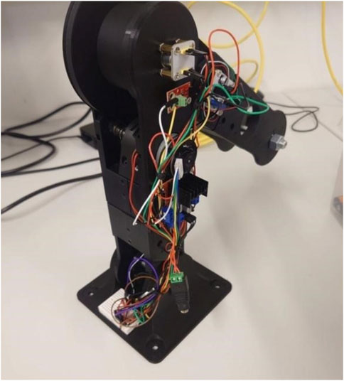
FIGURE 6. Robotic arm prototype realized at University of Agder (Norway).
3.2 Material testing results
3.2.1 FTIR-ATR analysis
As one may notice in Figure 7, the FTIR-ATR spectrum shows specific peaks of PEKK structure with the following absorption bands: peak at 3,063 cm−1 assigned to the stretching vibration of asymmetric C-H bond involved into double bond or aromatic ring; peaks at 2,922/2,852 cm−1 attributed to stretching vibration of asymmetric C-H bond; peak at 1,651 cm−1 corresponding to the stretching vibration of C=O from carbonyl group; peak at 1,584 cm−1 assigned to the stretching vibration of C=C bond; peak at 1,493 cm−1 attributed to the bending vibration of C-H bond; peak at 1,230 cm−1 assigned to the stretching vibration of C-O/O-C-O bond.
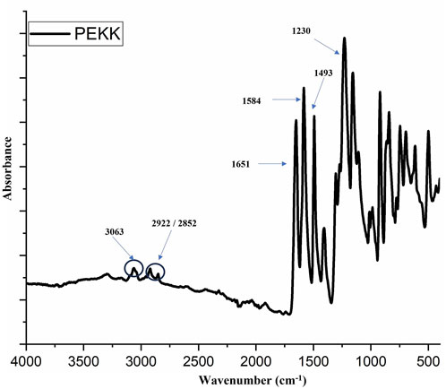
FIGURE 7. FTIR-ATR spectrum of PEKK material.
Comparing the FTIR results of current research with the ones reached by other researchers in case of PEKK material, distinct differences in the FTIR spectra can be noted, confirming the unique material composition of PEKK material. The 1,300–1,050 cm−1 range, usually associated with diphenyl ether group (C-O-C) rotation and stretching, as well as the presence of the ketone group between benzene rings instead of an oxygen bridge contribute to the enhanced material properties of PEKK (Lu et al., 2022). Absorption peaks level is also significant to the structure of the material. Peaks at 3,063 cm−1, 2,922/2,852 cm−1, 1,651 cm−1, 1,584 cm−1, 1,493 cm−1, and 1,230 cm−1 reached within the current research correspond to various functional groups integral to PEKK’s molecular architecture. In comparison, in the literature are highlighted characteristic peak at ∼1,645.0 cm−1 which are associated with carbonyl groups connected between two benzene ring, a significant aspect of the PEKK’s molecular structure (Paszkiewicz et al., 2023).
FTIR spectra of PEKK material in the literature confirms the C–H bonds of the benzene ring, the C=O bond of ketone, C=C bond of the aromatic ring, and the ether bond (C-O). Notably, the peaks at 1,644 cm−1, 1,493 cm−1, and 920 cm−1 are attributed to the diphenyl ketone group, with the peak at 1,584 cm−1 linked to the C=C stretching vibrations in the aromatic ring. Furthermore, asymmetric stretching peaks of carbonyl at 1,401 cm−1 and 1,305 cm−1, along with additional peaks at 1,229 cm−1 and 1,153 cm−1 for C–O–C bond in diaryl groups are observed in the structure of PEKK material. The presence of hydroxyl groups is also indicated by a peak at 3,307 cm−1". This detailed spectral fingerprint underscores the distinct molecular structure of PEKK and its stability in various applications realized by additive manufacturing technologies (Şükür et al., 2023).
In terms of comparing the FTIR of PEKK material with FTIR results of PET-G material, it can be noticed that the presence of peaks associated with carbonyl groups (1,651 cm−1) and double bonds (3,063 cm−1) in PEKK indicates a more complex and varied chemical structure as compared to PET-G, which lacks in having such functional groups (Kulkarni and Narayan, 2023).
FTIR analysis of PEKK is more sensitive to small changes in chemical composition and structure as compared to PET-G and MED 857 (DraftWhite) materials. This increased sensitivity is advantageous in case of PEEK material for detecting impurities, changes in polymerization and variations in material quality (Kozior et al., 2022).
The presence of specific functional groups like carbonyl groups (1,651 cm−1) in PEKK make this material to be chemically more compatible as compared to PET-G and MED 857 (DraftWhite) materials. The carbonyl groups contribute to better resistance against chemical degradation in case of PEKK material. (Paszkiewicz et al., 2023).
The presence of functional groups like C=C bonds (1,584 cm−1) in the structure of PEKK material is important in the adhesion and bonding properties. This is critical mostly in cases in which strong and durable bonds are essential for structural integrity and performance of the realized components. (Chattaraj and Basu, 2022).
PEKK material is often used in high-performance applications such as robotic arms due to its superior thermal and mechanical properties. The detailed information provided by FTIR in case of PEEK confirms that this type of material meets the stringent requirements of such applications.
The FTIR analysis of PEKK reveals a highly ordered and crystalline structure. This crystallinity contributes to its excellent mechanical properties, including high tensile strength and stiffness. These properties make PEKK better suited for robotic arm applications where structural integrity is paramount. PET-G, while being a durable material, typically exhibits a more amorphous structure. This amorphous nature can result in lower tensile strength and stiffness compared to PEKK. In robotic arms, PET-G may be more prone to deformation and fatigue under constant stress. (Kluczyński et al., 2022).
MED 857 (DraftWhite) material may excel in certain robotic applications, but its long-term durability may not be as robust as PEKK, particularly when this material is being exposed to harsh environmental conditions (Patpatiya et al., 2022b).
3.2.2 EDS and SEM investigations
The EDS analyses of the top surface and cross section (see Figure 8A, B, respectively) confirm the chemical composition specific to PEKK (-C6H4-O-C6H4-CO-C6H4-CO-)n. Chlorine was detected in both cases, though the chemical identity of the chlorine-containing compounds was not elucidated by the analyses. Such compounds probably resulted from synthesis catalysts or various additives used in the manufacturing process. The EDS graphs and data analysis were performed with the Origin software.
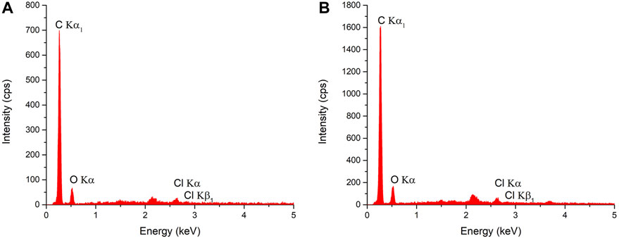
FIGURE 8. EDS analysis of (A) top surface and (B) section of sample made of PEKK material.
The high ratio of carbon content (83.5%) in PEKK material is crucial, particularly when compared to materials like PET-G (having 65% ratio of carbon content) and MED 857 (DraftWhite) (having approximate 30% ratio of carbon content), as it confers a suite of enhanced properties (Baek et al., 2022; Gabalski et al., 2023; Kulkarni and Narayan, 2023). Carbon atoms, that are integral to the polymer matrix, contribute significantly to the overall stability and strength of material. They do so by increasing the intermolecular forces within the polymer chains, leading to a denser structure. This increase in intermolecular forces directly translates to heightened mechanical properties such as tensile strength and stiffness, which represents essential characteristics for applications that demand durability and rigidity, such as in the construction of the robotic grippers (Karthik et al., 2023).
Furthermore, the presence of a higher ratio of carbon in PEKK results in superior thermal stability. The components made from PEKK can withstand higher operating temperatures without losing structural integrity, this being one critical factor in the high-performance and longevity of robotic grippers, which often work in varied and demanding thermal environments (Tadini et al., 2017). Additionally, the robust carbon structure in PEKK provides excellent wear resistance, reducing the rate of material degradation under mechanical stress and repetitive motions, thereby extending the service life of the robotic grippers (Pedroso et al., 2022).
In essence, the higher carbon ratio in PEKK represents a fundamental enhancement to the material’s molecular architecture. This aspect is highly important in the case of applications when a strong and rigid material is required for the precise and demanding operations realized by the robotic grippers (Kotzur et al., 2022).
In Figure 9 there is presented the SEM analysis of PEKK used in Fused Filament Fabrication (FFF), revealing notable structural characteristics when compared with PET-G and MED 857 (DraftWhite) materials.

FIGURE 9. SEM analysis of PEKK surface manufactured by FFF: (A) x100, (B) x500 (C) x5000 SEM analysis of PEKK after breaking in the ambient atmosphere: (D) x100, (E) x500 (F) x5000 SEM analysis of PEKK after the traction test in liquid nitrogen: (G) x100, (H) x500, (I) x5000 SEM analysis of edge PEKK surface manufactured by FFF: (J) x100, (K) x500 (L) x5000.
As one may notice in Figure 9A–C, top surface micrographs of FFF-produced PEKK samples display a finely layered structure with layer thickness precision in the range of 439–442.9 µm. Notably, Figure 9A illustrates this precision, which is on the size to tens of nanometers. The surface topography of the PEKK, as can be seen in Figure 9B is predominantly smooth, marked by small, scale-like protuberances characteristic of the FFF process, with occasional porosities that can be seen on a higher magnification in Figure 9C.
Fractured surfaces of PEKK samples, which have been broken in ambient atmosphere conditions, are examined in Figure 9D–F. The freshly broken surface (Figure 9D) transitions to a fine, layered structure with grooves as can be observed in Figure 9E, leading to the visualization of parallel fibrous structures that can be seen on a higher magnification in Figure 9F. These images highlight the material’s layered integrity and fiber alignment, which are indicative of the material’s mechanical properties.
The brittleness induced by samples broken in cryogenic conditions is showcased in Figure 9G–I, where SEM analysis post-fracture displays distinct structural changes. Spherical porosities ranging from 34.03 to 46.60 µm in diameter are scattered throughout, as they were captured in Figure 9H, and Figure 9I emphasizes on a higher magnification the specific fracture surface defects of the samples due to increased brittleness.
The edge area of PEKK samples exhibits signs of imperfect layer adhesion (Figure 9J–L), with Figure 9J, K is highlighting the presence of small protuberances and Figure 9L revealing spherical voids, further illustrating the influence of the FFF additive technology on material structure.
By comparing the structures of PEKK material with the ones of PET-G and MED 857 (DraftWhite) materials available in the literature it is possible to notice that PEKK material has a significant refined layer distribution, with precision reaching tens of nanometers, superior than the one of PET-G and MED 857 (DraftWhite) materials in terms of layer uniformity and precision (Zohdi and Yang, 2021; Sava et al., 2023). This high level of detail, that is highly crucial for additive manufacturing applications, is not as obvious in the case of PET-G and MED 857 materials, which exhibit rougher and more varied layer structures. The surface of PEKK, characterized by a smooth finish highlighted by distinctive protuberances—characteristic of FFF manufacturing process—is contrasted by the rougher and less consistent surfaces of parts made of PET-G and MED 857 materials, indicating a superior surface quality in case of parts made of PEKK material (Shinde et al., 2022). Furthermore, the fracture surface analysis of PEKK samples reveals intricate patterns of grooves and defects, offering a deeper understanding of its mechanical behavior under stress, unlike the less complex fracture characteristics seen in the case of samples made of PET-G and MED 857 materials (Amza et al., 2021). Overall, the comparison highlights PEKK’s superior structural and surface qualities, which are essential for its performance in high-stress applications, like the ones of robotic grippers.
3.3 Finite element analysis results
The finite element model allowed the determining of the critical values in case of the vertical displacement which has been applied at the free end of the robotic tooltip at which the maximum value of the von Mises equivalent stress becomes equal to the yield stress of each material, respectively at 14 mm in case of PET-G material, 18.8 mm in case of PEKK material and 26.2 mm in case of MED 857 (DraftWhite) material. Figure 10 lists the maximum values of the von Mises equivalent stress σeq, max determined by the SolidWorks Simulation finite element program in case of values of the vertical displacement d enforced at the free end of the robotic tooltip that were mentioned.

FIGURE 10. Distribution of the von Mises equivalent stress at the level of the tooltip components (A) made of PET-G, as obtained by enforcing a vertical displacement of 14 mm; (B) made of PEKK, as obtained by enforcing a vertical displacement of 18.8 mm and (C) made of MED 857 (DraftWhite), as obtained by enforcing a vertical displacement of 26.2 mm.
As one may notice in Figure 10, the maximum von Mises equivalent stress that was reached at the level of the tooltip components was 48.1 MPa in case of PET-G material (Figure 10A, 84,7 MPa in case of PEKK material (Figure 10B and 47.7 MPa in case of MED 857 (DraftWhite) material (Figure 10C.
3.4 Manufacturing results and process economic coefficients
Of the performed manufacturing processes, 100% succeeded, without any major errors, concerning all the aspects (machine, software, code and material). The images presented in Figure 11 show sets of parts manufactured using various materials and technologies. The parts were visually examined to find any major or minor errors of representation of their shape and surface.
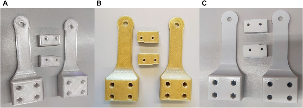
FIGURE 11. Manufactured samples, (A) FFF, PET-G material; (B) FFF, PEKK material; (C) PolyJet, MED 857 (DraftWhite) material.
Regarding the manufacturing processes and their comparison, the following observations can be made:
• The FFF manufacturing process using PET-G material shown in Figure 11A went smoothly without any noticeable errors or problems. The manufactured parts are free of visual and shape errors, with noticeable, expected staircase effect and surface roughness. Also, due to applied infill of 30%, they are considerably lightweight—it does not affect the long part of the tooltip, only the bulk, lower part.
• The FFF manufacturing using PEKK material shown in Figure 11B was also done without any disturbances and the parts do not present any major errors or inconsistencies. However, it is noteworthy that the process took much more time—layer deposition was very long, as well as material preparation (drying in a dedicated furnace).
• The PolyJet process of samples shown in Figure 11C also went smoothly without any disturbances. The obtained parts were very smooth and precisely represent the part geometry, without visible staircase effect, having a partially shiny surface thanks to low layer thickness. They were also considerably heavy and rigid—the standard PolyJet process settings do not allow openwork internal structure, so the parts are monolithic. For all the materials, fitting and assembling the complete tooltip was not a problem. Acceptable accuracy was obtained, although the least visual looseness was noted for parts made of PolyJet technology, which was to be expected due to high machine accuracy and very low layer thickness.
The summary of economic coefficients of the printouts is presented in Table 1.
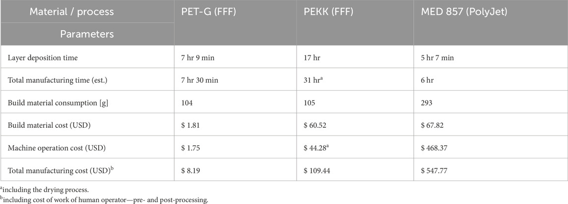
TABLE 1. Time and cost of manufacturing for the three considered materials.
The following observations can be made related to the time and cost indicators of the considered processes in comparison:
• FFF manufacturing out of PEKK material is the longest process of all three tested, both in terms of layer manufacturing (more than 2 times longer than using PET-G material, but also 3 times longer than the MED 857 (DraftWhite) material and preprocessing (13 h of drying). As the material is also costly and requires a special, expensive machine to process, this variant is significantly, 13 times more expensive than standard FFF 3D printing of PET-G material.
• In terms of the PolyJet process—it is in total much shorter than manufacturing of PEKK and even standard FFF process (PET-G material). It is also noteworthy that in the PolyJet technology, horizontal increase in build chamber filling with more parts does not considerably increase build time—for a single set of samples it was approx. 5 h, for two sets—6,5 h, for three—approx. 8 h). Considering a very low layer thickness (18 µm) and high infill (monolithic, non-controllable), efficiency of PolyJet process can be considered as very high.
• The PolyJet machine has an immense purchase cost, by a large margin, which makes the process the most expensive of all with the assumed calculation methodology (5 times more expensive than PEKK and almost 70 times more expensive than standard FFF 3D printing of PET-G material).
• It can be observed that for the MED 857 (DraftWhite) material and the PolyJet process, consumption was much higher than in the case of FFF processes. Of the 293 g consumed by the PolyJet device, however, only 226 g are actually used for building the part, the rest is wasted (machine uses all 6 installed cartridges and purges them during each print). It is still a considerably larger amount than in the case of FFF processes—however, in PolyJet there is no partial internal filling, meaning that the parts are monolithic. This does not influence the beam part of the tooltip, as it has low wall thickness—however the bulk part of the tooltip is affected and the parts of PolyJet are considerably heavier due to that fact.
• All three processes and materials allow achieving acceptable results in terms of process stability, as well as lack of major errors in shape and accuracy, enabling proper fit. As the cost difference between typical, easily accessible FFF process and the two other (high-performance) processes is significant, it seems not advisable to use these for regular production of customized robotic arm parts, unless dedicated properties of high-performance materials (such as chemical or thermal resistance, as well as increased strength) are to be utilized.
3.5 Mechanical test experiments results
In the case of all the samples, the bending test was realized without disturbances. Most samples were broken entirely during the tests, with an exception of all PET-G material samples, which cracked, but did not disjoint. The experiment was always stopped shortly after decrease of loading force was observed, hence lack of full failure of samples of these materials. Also, one sample of MED 857 (DraftWhite) material was not visibly cracking—heavy plastic deformation occurred, but without breaking the continuity of material. All the other samples of the batch failed at comparable loads and the failure was similar in observation to the “brittle fracture” mechanism, with sharp edges and smooth surfaces at the locations of failure.
Figure 12A–C presents juxtaposition of samples made of PET-G, PEKK and MED 857 (DraftWhite) material after the test.

FIGURE 12. Samples made of (A) PET-G, (B) PEKK and (C) MED 857 (DraftWhite) materials after strength testing.
Figure 13A–CB present examples of load-displacement diagrams for all three materials, obtained from the testing machine software.

FIGURE 13. Load-displacement diagram for samples made of (A) PET-G, (B) PEKK and (C) MED 857 (DraftWhite) materials.
Table 2 presents the main numerical results of strength testing, calculated on average for 3 samples—maximal registered forces, forces at break, maximal displacements and maximal stresses calculated using the formula shown in earlier chapters.

TABLE 2. Results of strength tests of robotic arm grippers made of different materials and comparison of the experimental data with the results reached by numerical simulation.
Analyzing the results, the following observations can be made:
• As one may notice by examining Figure 12, the abscissae corresponding to the maxima of the load-displacement curves resulting from experiments are well approximated by the previously mentioned numerical (CAE) results that were presented in Figure 10. It is to be specified that the results presented in Figure 10 depend on the mechanical parameters (elastic constants) of the material for which the numerical simulation has been performed. For example, if the displacement of the tooltip made of PEKK were 14 mm (less than 18.8 mm—case shown in Figure 10B), the maximum value of the von Mises equivalent stress would be smaller than 84.7 MPa (as shown in Figure 10B) but different from that obtained in the case of PET-G for the 14 mm displacement of the tooltip end (see Figure 10A). In general, the mechanical response of materials having different elastic constants is not the same even if the external loads and kinematic restraints are identical.
• Table 2 compares the vertical displacement of the tooltip d [mm] at which SolidWorks Simulation predicts that the maximum value of the von Mises equivalent stress becomes equal to the material yield stress (as predicted by SolidWorks Simulation) with the vertical displacement of the tooltip dexp [mm] at which the maximum testing force occurred inthe bending experiments (Figure 13). As one may notice by analyzing the relative errors ɛr of the numerical predictions 100×(d - dexp)/dexp [%] listed in Table 2, the numerical results are quite close to the experimental data for all materials.
• As expected, performance of PEKK samples is considerably higher than PET-G samples—more than twice a load was achieved before failure of the part.
• Displacements at maximum load are almost the same for both filament materials—and almost 40% higher for the MED 857 (DraftWhite) material. This type of material which is based on resin also was less prone to fracturing.
• The PEKK material samples, as opposed to PET-G samples, broke almost instantaneously and the failure was visible at the whole cross-section (of a single beam). It might be considered more of a brittle fracture than plastic deformation in this case. In the case of PET-G, much more plastic behavior was observed, with no visible breaking of the beam parts, but with heavy plastic deformation instead.
• The MED 857 (DraftWhite) material was the strongest, by a large margin (more than 50% difference when comparing with the PEKK material). Also, the highest displacement was achieved in this case. This may be partially attributed to monolithic infill of the part, making it heavier in total—but also thanks to the low layer thickness and different method of layer deposition, the connections between layers may be stronger than in FFF technology, resulting in higher performance under load.
• Comparison of mechanical characteristics in terms of strength obtained in the experiment and declared by the producer brings interesting observations. For the PET-G, experimental value (31 MPa) was twice lower than the declared value of 64 MPa. For the PEKK material, declared and experimental values were comparable (experiment—slightly less than declared, at 70 MPa versus approx. 80 MPa as declared). However, for the MED 857 (DraftWhite) material, the obtained strength (100 MPa) was considerably higher than the declared value (70–85 MPa). The discrepancy in this case might be a result of simplifications during stress calculations, but only to a certain extent—this does not fully justify almost 30% of difference between material sheet data and experimental data. More experiments on different geometries would be needed to be performed in the future regarding the mechanical characteristics and behavior of this material.
3.6 Discussion
In the experimental studies, it was found that the PEKK material—which is a high-performance material used for additive manufacturing by material extrusion—indeed has much better strength properties than generic materials used in regular 3D printing processes, like PET-G and MED 857 (DraftWhite) materials. The difference is considerable—the material is able to sustain at least twice the load, with the same deformation, as compared to the standard PET-G material. At the same time, the PEKK material processing using material extrusion 3D printing is not troublesome, provided appropriate temperature conditions are used—which is still not common in the case of other high-performance materials (e.g., like in the case of composite filaments with carbon fibers). The manufacturing of this material is a stable and repeatable process, requiring almost no post processing. The obtained parts present acceptable visual quality and shape accuracy, enabling proper assembly of obtained machine parts.
However, costs of production in the case of this material—as well as with other materials of this group are very high. The PEKK material, as of current market availability, is 30 times more expensive than regular FFF filaments (such as PET-G or MED 857 materials). Also, it requires considerably more expensive and less available machines to perform the processing. Totally, cost of producing the robotic gripper parts as presented in this article was 13 times higher for PEKK than of a standard material. Another disadvantage is drying time, which is almost as long as manufacturing (in the case of parts considered in this article) and also much longer than the whole production process using the filaments not needing the drying.
As such, the authors believe it is only advisable (in practical conditions), if typical FFF filaments do not allow to obtain proper loading strength—however, in such case it could be advisable to change part geometry, instead of highly increasing production cost by using a very expensive material. Another scenario of use would be if typical materials do not fulfill special criteria, e.g., of temperature or chemical resistance. Only then would it be practical to use PEKK as a replacement.
The comparison of the FFF technology with the PolyJet technology also brought some interesting insights. The PolyJet machine is a very expensive device and its purchase and operation costs vastly increase the total cost of obtained parts. However, if the machine costs were taken aside, the material itself (which is a generic UV resin supplied by the machine producer) is actually less expensive than PEKK. At the same time, it excels at each criterion taken into account in this article—the parts are very strong (more than 50% stronger than PEKK parts and more than 3 times stronger than PET-G parts, in the conducted experiment), accuracy and surface quality are much better than in FFF (almost no staircase effect visible, with a shiny, smooth surface without additional processing) and the production time is also shortest of all three processes considered in the article. It might be considered practical more than PEKK (or other high-performance polymers) if the PolyJet machine is readily available (thus, taking the purchase cost out of the equation)—in a shorter time, parts of better characteristics can be obtained.
The PolyJet process also has certain disadvantages. Aside from the enormous price, the material waste is quite high—extra material is consumed of all cartridges, regardless of batch size (the material waste is even larger when considering that FFF filaments are fully recyclable, while polymerized UV resin—not as much). Considering also that times of manufacturing do not increase significantly while adding more parts to the batch (provided that maximal vertical dimension, i.e., layer amount, stays the same), it would be advisable in practical conditions to produce as large batches as feasible when dealing with that technology. Also, internal filling cannot be reduced (or otherwise controlled), as such the parts can be bulky—proper geometry would need to be obtained, taking these considerations into account. In terms of the strength—the parts were very durable during the experiment described in this article, however from the author’s experience—this may not be the case with small geometry parts and lower wall thicknesses. Further examinations on various parts and materials would need to be done to further decide if PolyJet can excel over FFF and in which applications, in terms of strength.
Anyhow, the experiment has proven that it is certainly possible to manufacture customized robotic arms using 3D printing technologies. The robotic gripper presented in the article is just an exemplary device—of course in the case of mass production, additive technologies would not be feasible. But in the case of highly customized devices, such as robotic prosthetic hands, legs or exoskeletons and their parts, additive manufacturing may be the way to go. Therefore, it is important to know if the currently available high performance materials and processes allow obtaining parts of considerable strength and accuracy. The experimental and analytical results state that this is the case.
4 Conclusions
In this article, it was presented how the high-performance materials and 3D printing technologies like Fused Filament Fabrication (FFF) or Polyjet technology can be used to produce an exemplary biomechatronic device—part of a robotic gripper.
As it was shown in the article, the advanced chemical structure of PEKK, characterized by distinctive carbonyl groups and double bonds, underscores its enhanced resistance and compatibility as compared to PET-G and MED 857 (DraftWhite) materials. This complexity not only augments its sensitivity in FTIR analysis, crucial for identifying impurities and assessing material quality, but also strengthens its adhesion and bonding properties that are essential for high-performance applications like robotic arms. The crystalline nature of PEKK further amplifies its mechanical robustness, offering superior strength and stiffness, making it an ideal choice for robotic components where enduring structural integrity is paramount. In contrast, the amorphous structures of PET-G and MED 857 materials may exhibit more vulnerability under sustained stress. In essence, PEKK stands out as a preferred material for the fabrication of resilient and reliable robotic systems, substantiated by its exceptional chemical and mechanical characteristics.
As EDS analyzes emphasized, PEKK material, with its enhanced carbon composition, unequivocally surpasses PET-G and MED 857 (DraftWhite) in strength and durability, marking it as a preferred choice for high-demand applications like robotic arms. The material’s exceptional fine layer distribution, evidenced by a microscopic examination, underscores its superior precision and control in additive manufacturing compared to the less uniform layers of PET-G and MED 857 (DraftWhite). The SEM analysis highlights PEKK’s smooth and consistent surface, this aspect being revealed also by the PEKK’s intricate fracture surfaces, offering deeper insights into its superior performance under stress, underscoring its reliability in high-performance applications. In contrast, PET-G and MED 857 (DraftWhite) exhibit rougher textures and less detailed fracture surfaces, highlighting PEKK’s advanced material behavior and stability.
In terms of CAE analysis, the results obtained from finite element simulations, showed that each of the analyzed materials (PET-G, PEKK and MED 857 (DraftWhite) exhibited a consistent, incremental rise in stress, reflecting their escalating response to enhanced loading. This information has been considered crucial as it signifies the distinct mechanical resilience and capabilities of PET-G, PEKK-A, and MED 857 (DraftWhite) materials, thereby aiding in the informed selection of materials for specific load-bearing applications in robotic tooltips. The observed trends underscore the heightened stress tolerance of PEKK-A and MED 857 (DraftWhite) materials as compared to PET-G, influencing their preference in high-performance applications.
Based on results that were reached through mechanical testing experiments which were in close correlation with the ones reached through CAE analyses that were realized, it was possible to determine that PEKK, despite its superior performance compared to PET-G, exhibited brittle fracture characteristics, snapping suddenly under load, contrary to the more plastic deformation that has been observed in case of other tested materials like PET-G. The resilience of MED 857 (DraftWhite) markedly overshadowed others, supporting loads over 50% higher than PEKK and showcasing the least susceptibility to fracturing, attributing to its monolithic infill and stronger inter-layer connections from a distinct layer deposition method.
An interesting divergence between experimental and declared mechanical strengths was noted, particularly in the case of PET-G and MED 857 (DraftWhite) materials. While PEKK’s experimental and declared values aligned closely, PET-G’s experimental strength was half the declared value, and MED 857 (DraftWhite) exceeded its declared strength by almost 30%, signaling possible simplifications in stress calculations or the need for further diversified geometrical testing to ascertain the material’s mechanical characteristics comprehensively.
In terms of 3D printing processes, crucial insights into the practicalities and challenges of each method have been provided. FFF manufacturing with PET-G and PEKK materials went seamlessly; producing parts with acceptable accuracy and no major errors, with a noted staircase effect and surface roughness in case of PET-G material. PEKK, while offering quality outputs was notably time-intensive and costly, making it a less feasible choice for regular production. The process demands prolonged layer deposition and material preparation time, leading to significant production delays in the manufacturing process. In contrast, the PolyJet process offers enhanced efficiency, yielding smooth and highly accurate parts, demonstrating its superiority in achieving detailed geometrical representation and fine layer thickness. This precision, however, comes at a steep cost. Despite its shorter manufacturing time, the high purchase and operational costs of the PolyJet machine make it the most expensive among the tested processes, presenting a barrier for its adoption in regular production of robotic parts. Furthermore, the PolyJet process results in substantial material consumption and wasting materials during the print. This, coupled with the creation of monolithic, heavier parts, underscores the limitations of this technology, despite its evident advantages in precision and finish.
In a cost and time-effective analysis, while all processes deliver satisfactory results in terms of stability and accuracy, the financial and time investment required for PEKK and PolyJet processes does not align with their output benefits for regular production of robotic arm parts. The utilization of these high-performance processes would only be judicious if specific, advanced material properties are imperative for the application, emphasizing the need for a balanced consideration of cost, time, and material performance in selecting the suitable manufacturing processIn the further studies, it would be worth performing other tests on high-performance materials, such as fatigue tests, tests of chemical and temperature resistance, dimensional accuracy studies and others. Also, a second direction of studies should include producing actual biomechatronic devices (such as orthoses or prostheses) and testing their use with real patients, to provide more answers about practical possibilities of using the current generation of 3D printing technologies in current trend with the new types of materials that are expanding and occurring on the market.
Data availability statement
The original contributions presented in the study are included in the article/supplementary material, further inquiries can be directed to the corresponding author.
Author contributions
RP: Writing–original draft, Resources, Supervision, Validation, Visualization. FS: Conceptualization, Funding acquisition, Validation, Writing–review and editing, Resources. MO: Software, Data curation, Writing–review and editing. D-IB: Formal Analysis, Investigation, Project administration, Writing–original draft. ZC: Methodology, Writing–review and editing. NI: Formal Analysis, Methodology, Writing–review and editing. IR: Formal Analysis, Methodology, Writing–review and editing. ST: Formal Analysis, Data curation, Software, Writing–review and editing. FG: Conceptualization, Data curation, Investigation, Project administration, Resources, Supervision, Writing–original draft. WK: Investigation, Methodology, Writing–review and editing. RW: Methodology, Validation, Writing–review and editing. DC: Data curation, Software, Validation, Writing–original draft. MZ: Formal Analysis, Software, Writing–review and editing. PW: Data curation, Software, Writing–review and editing.
Funding
The author(s) declare financial support was received for the research, authorship, and/or publication of this article. This research was financially supported by SEE grants 2014-2021, project no. 21-COP-0019 (contract no. 541/15 February 2022) entitled European Network for 3D Printing of Biomimetic Mechatronic Systems (EMERALD). This research was also supported by the Biomechatronics and Collaborative Robotics research group at the Top Research Center Mechatronics (TRCM), University of Agder (UiA), Norway.
Conflict of interest
MZ was employed by the company Bizzcom s r o. PW was employed by the company B3D s c.
The remaining authors declare that the research was conducted in the absence of any commercial or financial relationships that could be construed as a potential conflict of interest.
Publisher’s note
All claims expressed in this article are solely those of the authors and do not necessarily represent those of their affiliated organizations, or those of the publisher, the editors and the reviewers. Any product that may be evaluated in this article, or claim that may be made by its manufacturer, is not guaranteed or endorsed by the publisher.
References
Amza, C. G., Zapciu, A., Constantin, G., Baciu, F., and Vasile, M. I. (2021). Enhancing mechanical properties of polymer 3D printed parts. Polymers 13, 562. doi:10.3390/polym13040562
Andersson, R., and Björsell, N. (2022). The energy consumption and robust case torque control of a rehabilitation hip exoskeleton. Appl. Sci. 12, 11104. doi:10.3390/app122111104
Arena, P., Bucolo, M., Buscarino, A., Fortuna, L., and Frasca, M. (2021). Reviewing bioinspired technologies for future trends: a complex systems point of view. Front. Phys. 9. doi:10.3389/fphy.2021.750090
Arleo, L., Stano, G., Percoco, G., and Cianchetti, M. (2021). I-support soft arm for assistance tasks: a new manufacturing approach based on 3D printing and characterization. Prog. Addit. Manuf. 6, 243–256. doi:10.1007/s40964-020-00158-y
Aylar, A., Faezeh, H., and Saeed, B. (2021). Robotic home-based rehabilitation systems design: from a literature review to a conceptual framework for community-based remote therapy during COVID-19 pandemic. Front. Robot. AI 8, 8. doi:10.3389/frobt.2021.612331
Baek, I., Lim, C.-M., Park, K. Y., and Ryu, B. K. (2022). Enhanced metal coating adhesion by surface modification of 3D printed PEKKs. Coatings 12, 854. doi:10.3390/coatings12060854
Bai, W., Fang, H., Wang, Y., Zeng, Q., Hu, G., Bao, G., et al. (2021). Academic insights and perspectives in 3D printing: a bibliometric review. Appl. Sci. 2021, 8298. doi:10.3390/app11188298
Barrera, S. A., Blanco, O. A., Martínez, R. E., Gómez, B., Abúndez, P. A., Campos, A. R., et al. (2022). State of the art review of active and passive knee orthoses. Machines 2022. doi:10.3390/machines10100865
Chattaraj, S., and Basu, S. (2022). Coarse-graining strategies for predicting properties of closely related polymer architectures: a case study of PEEK and PEKK. J. Mater. Res. 37, 1–12. doi:10.1557/s43578-021-00332-0
Chaudhry, M. S., and Czekanski, A. (2020). Evaluating FDM process parameter sensitive mechanical performance of elastomers at various strain rates of loading. Materials 13, 3202. doi:10.3390/ma13143202
Chen, J. V., Dang, A. B. C., and Dang, A. (2021). Comparing cost and print time estimates for six commercially-available 3D printers obtained through slicing software for clinically relevant anatomical models. 3D Print Med. 7, 1. doi:10.1186/s41205-020-00091-4
Coyle, S., Majidi, C., Leduc, P., and Hsia, K. (2018). Bio-inspired soft robotics: material selection, actuation, and design. Extreme Mech. Lett. 22, 51–59. doi:10.1016/j.eml.2018.05.003
Ding, Z., Tang, N., Huang, J., Cao, X., and Wu, S. (2023). Global hotspots and emerging trends in 3D bioprinting research. Front. Bioeng. Biotechnol. 11, 1169893. doi:10.3389/fbioe.2023.1169893
Gabalski, M., Smith, K., Hix, J., and Zinn, K. (2023). Comparisons of 3D printed materials for biomedical imaging applications. Sci. Technol. Adv. Mater. 24. doi:10.1080/14686996.2023.2273803
Gawade, V., Galkin, G., Guo, Y. B., and Guo, W. G. (2022). Quantifying and modeling overheating using 3D pyrometry map in powder bed fusion. Manuf. Lett. 33, 880–892. doi:10.1016/j.mfglet.2022.07.107
Gere, J. M., and Goodno, B. J. (2012). Mechanics of materials. Boston, Massachusetts: Cengage learning.
Golhin, A. P., Tonello, R., Frisvad, J. R., Sotirios, G., and Are, S. (2023). Surface roughness of as-printed polymers: a comprehensive review. Int. J. Adv. Manuf. Technol. 127, 987–1043. doi:10.1007/s00170-023-11566-z
Górski, F., Wichniarek, R., Kuczko, W., and Żukowska, M. (2021). Study on properties of automatically designed 3d-printed customized prosthetic sockets. Materials 14 (18), 5240. doi:10.3390/ma14185240
Górski, F., Wichniarek, R., Kuczko, W., Żukowska, M., Lulkiewicz, M., and Zawadzki, P. (2020). Experimental studies on 3D printing of automatically designed customized wrist-hand orthoses. Materials 13 (18), 4091. doi:10.3390/ma13184091
Gülcan, O., Günaydın, K., and Tamer, A. (2021). The state of the art of material jetting—a critical review. Polymers 13, 2829. doi:10.3390/polym13162829
Hornyák, I., Jedlovszky-Hajdú, A., and Kehr, S. (2023). Editorial: biomaterial applications in soft tissue engineering and replacement. Front. Bioeng. Biotechnol. 11, 1227021. doi:10.3389/fbioe.2023.1227021
Iftekar, S. F., Aabid, A., Amir, A., and Baig, M. (2023). Advancements and limitations in 3D printing materials and technologies: a critical review. Polymers 15, 2519. doi:10.3390/polym15112519
Karthik, R., Vedant, M., Pavan, S. R., Pedro, P. M., Conor, T. M., and Ronan, M. O. (2023). An investigation of the influence of matrix properties and fibre–matrix interface behaviour on the mechanical performance of carbon fibre-reinforced PEKK and PEEK composites. Compos. Part A Appl. Sci. Manuf. 165, 107359. doi:10.1016/j.compositesa.2022.107359
Kim, G.-T., Go, H.-B., Yu, J.-H., Yang, S.-Y., Kim, K.-M., Choi, S.-H., et al. (2022). Cytotoxicity, colour stability and dimensional accuracy of 3D printing resin with three different photoinitiators. Polymers 14, 979. doi:10.3390/polym14050979
Kluczyński, J., Szachogluchowicz, I., Torzewski, J., Sniezek, L., GrzelakBudzik, K. G., Przeszłowski, Ł., et al. (2022). Fatigue and fracture of additively manufactured polyethylene terephthalate glycol and acrylonitrile butadiene styrene polymers. Int. J. Fatigue 165, 107212–107310. doi:10.1016/j.ijfatigue.2022.107212
Korkees, F., Allenby, J., and Dorrington, P. (2020). 3D printing of composites: design parameters and flexural performance. Rapid Prototyp. J. 26, 699–706. doi:10.1108/RPJ-07-2019-0188
Kotzur, K., Doll, G., and Hermann, P. (2022). Analysis and development of a brazing method to weld carbon fiber-reinforced poly ether ketone ketone with amorphous PEKK. Polym. Compos. Sci. 8, 145–155. doi:10.1080/20550340.2022.2122119
Kozior, T., Mamun, A., Trabelsi, M., and Sabantina, L. (2022). Comparative analysis of polymer composites produced by FFF and PJM 3D printing and electrospinning technologies for possible filter applications. Coatings 12, 48. doi:10.3390/coatings12010048
Kramberger, A., Gams, A., Nemec, B., Chrysostomou, D., Madsen, O., and Ude, A. (2017). Generalization of orientation trajectories and force-torque profiles for robotic assembly. Robotics Aut. Syst. 98, 333–346. doi:10.1016/j.robot.2017.09.019
Krawczuk, M., and Palacz, M. (2021). Special issue “applications of finite element modeling for mechanical and mechatronic systems”. Appl. Sci. 11, 5170. doi:10.3390/app11115170
Kulkarni, A., and Narayan, R. (2023). Morphology, mechanical properties, and biodegradability of modified thermoplastic starch/PETG blends with in situ generated graft copolymers. Sustainability 15, 2227. doi:10.3390/su15032227
Li, Z., Yang, C., and Burde, E. (2016). An overview of biomedical robotics and bio-mechatronics systems and applications. IEEE Trans. Syst. Man, Cybern. Syst. 46, 1–6. doi:10.1109/TSMC.2016.2571786
Lu, W., Li, C., Wu, J., Ma, Z., Zhang, Y., Xin, T., et al. (2022). Preparation and characterization of a polyetherketoneketone/hydroxyapatite hybrid for dental applications. J. Funct. Biomaterials 13, 220. doi:10.3390/jfb13040220
Luo, X., Cheng, H., and Wu, X. (2023). Nanomaterials reinforced polymer filament for fused deposition modeling: a state-of-the-art review. Polymers 15, 2980. doi:10.3390/polym15142980
Mercado-Colmenero, J. M., La Rubia, M. D., Mata-Garcia, E., Rodriguez-Santiago, M., and Martin-Doñate, C. (2020). Experimental and numerical analysis for the mechanical characterization of PETG polymers manufactured with FDM technology under pure uniaxial compression stress states for architectural applications. Polymers 12, 2202. doi:10.3390/polym12102202
Mick, S., Lapeyre, M., Rouanet, P., Halgand, C., Benois-Pineau, J., Paclet, F., et al. (2019). Reachy, a 3D-printed human-like robotic arm as a testbed for human-robot control strategies. Front. Neurorobot. 13, 65. doi:10.3389/fnbot.2019.00065
Mondal, D., Diederichs, E., and Willett, T. L. (2022). Enhanced mechanical properties of 3D printed nanocomposites composed of functionalized plant-derived biopolymers and calcium-deficient hydroxyapatite nanoparticles. Front. Mater 9. doi:10.3389/fmats.2022.833065
Moosavi, S. K. R., Zafar, M. H., and Sanfilippo, F. (2022). “A review of the state-of-the-art of sensing and actuation technology for robotic grasping and haptic rendering,” in Proceeding of the 5th International Conference on Information and Computer Technologies (ICICT), New York City (virtual), United States, March. 2022. doi:10.1109/ICICT55905.2022.00039
NguyenVuillaume, K. P., Hu, L., López-Beceiro, J., Cousin, P., Elkoun, S., and Robert, M. (2023). Recycled, bio-based, and blended composite materials for 3D printing filament: pros and cons—a review. Mat. Sci. App. 14, 148–185. doi:10.4236/msa.2023.143010
Pang, X., Yue, S., Huang, S., Xie, J., Wang, S., Yue, Y., et al. (2023). Effects of ambient humidity and sintering temperature on the tribological and antistatic properties of PEEK and CF/PEEK. Front. Mater. 10. doi:10.3389/fmats.2023.1197604
Paszkiewicz, S., Lesiak, P., Walkowiak, K., Irska, I., Miądlicki, K., Królikowski, M., et al. (2023). The mechanical, thermal, and biological properties of materials intended for dental implants: a comparison of three types of poly(aryl-ether-ketones) (PEEK and PEKK). Polymers 15, 3706. doi:10.3390/polym15183706
Patpatiya, P., Chaudhary, K., and Kapoor, V. (2022a). Reverse manufacturing and 3D inspection of mechanical fasteners fabricated using photopolymer jetting technology. MAPAN 37, 753–763. doi:10.1007/s12647-022-00561-6
Patpatiya, P., Chaudhary, K., Shastri, A., and Sharma, S. (2022b). A review on polyjet 3D printing of polymers and multi-material structures. Proc. Institution Mech. Eng. Part C J. Mech. Eng. Sci. 236, 7899–7926. doi:10.1177/09544062221079506
Pedroso, J. M., Enger, M., Bandeira, P., and Magalhães, F. D. (2022). Comparative study of friction and wear performance of PEK, PEEK and PEKK binders in tribological coatings. Polymers 14, 4008. doi:10.3390/polym14194008
PEKK-A (2023). PEKK material characteristics datasheet. https://get3d.pl/wp-content/uploads/2020/09/kimya_fiche_PEKK-A_en_GB.pdf (Accessed August 20, 2023).
PET-G (2023). Premium material characteristics datasheet. https://spectrumfilaments.com/wp-content/uploads/2022/05/en_tds_spectrum_petg_premium.pdf (Accessed August 18, 2023).
Salmi, M. (2021). Additive manufacturing processes in medical applications. Materials 14, 191. doi:10.3390/ma14010191
Sanfilippo, F., Hua, T., and Bos, S. (2020). “A comparison between a two feedback control loop and a reinforcement learning algorithm for compliant low-cost series elastic actuators,” in Proceeding of the 53rd Hawaii International Conference on System Sciences (HICSS 2020), Maui, Hawaii, United States of America, January, 2020, 881–890. doi:10.24251/HICSS.2020.110
Sanfilippo, F., and Pettersen, K. Y. (2015b). “OpenMRH: a modular robotic hand generator plugin for OpenRAVE,” in Proceeding of the IEEE Conference on Robotics and Biomimetics (ROBIO), Zhuhai, China, December, 2015, 1–6. doi:10.1109/ROBIO.2015.7407010
Sanfilippo, F., Salvietti, G., Zhang, H., Petter, H. H., and Prattichizzo, D. (2012). “Efficient modular grasping: an iterative approach,” in Proceedings of the 4th IEEE RAS & EMBS International Conference on Biomedical Robotics and Biomechatronics (BioRob), Rome, Italy, June, 2012, 1281–1286. doi:10.1109/BioRob.2012.6290693
Sanfilippo, F., Zhang, H., and Pettersen, K. Y. (2015a). “The new architecture of ModGrasp for mind-controlled low-cost sensorised modular hands,” in Proceeding of the IEEE International Conference on Industrial Technology (ICIT), Seville, Spain, March, 2015, 524–529. doi:10.1109/ICIT.2015.7125152
Sanfilippo, F., Zhang, H., Pettersen, K. Y., Salvietti, G., and Prattichizzo, D. (2014). “ModGrasp: an open-source rapid-prototyping framework for designing low-cost sensorised modular hands,” in Proceeding of the 5th IEEE RAS & EMBS International Conference on Biomedical Robotics and Biomechatronics (BioRob), São Paulo, Brazil, August, 2014, 951–957. doi:10.1109/BIOROB.2014.6913903
Sava, Ș.-D., Lohan, N.-M., Pricop, B., Popa, M., Cimpoeșu, N., Comăneci, R.-I., et al. (2023). On the thermomechanical behavior of 3D-printed specimens of shape memory R-PETG. Polymers 15, 2378. doi:10.3390/polym15102378
Shinde, V. V., Wang, Y., Salek, M. F., Auad, M. L., Beckingham, L. E., and Beckingham, B. S. (2022). Material design for enhancing properties of 3D printed polymer composites for target applications. Technologies 10, 45. doi:10.3390/technologies10020045
Stratasys (2023). MED 857 (DraftWhite) material characteristics datasheet. https://www.stratasys.com/siteassets/materials/materials-catalog/polyjet-materials/draftwhite/draftwhite-med857---en-a4-data-sheet.pdf?v=49d81c (Accessed August 23, 2023).
Şükür, E., Elmas, S., Eskizeybek, V., Sas, H., and Yildiz, M. (2023). An experimental implication of long-term hot-wet-aged carbon fiber/polyether ketone ketone composites: the impact of automated fiber placement process parameters and process-induced defects. J. Appl. Polym. Sci. 140. doi:10.1002/app.54076
Tadini, P., Grange, N., Chetehouna, K., Gascoin, N., Senave, S., and Reynaud, I. (2017). Thermal degradation analysis of innovative PEKK-based carbon composites for high-temperature aeronautical components. Aerosp. Sci. &Technology 65, 106–116. doi:10.1016/j.ast.2017.02.011
Tofail, S. A. M., Koumoulos, E. P., Bandyopadhyay, A., Bose, S., O’Donoghue, L., and Charitidis, C. (2018). Additive manufacturing: scientific and technological challenges, market uptake and opportunities. Mater. Today 21, 22–37. doi:10.1016/j.mattod.2017.07.001
Tuan, H. M., Sanfilippo, F., and Hao, N. V. (2021). Modelling and control of a 2-DOF robot arm with elastic joints for safe human-robot interaction. Front. Robotics AI 8, 679304. doi:10.3389/frobt.2021.679304
Tuan, H. M., Sanfilippo, F., and Hao, N. V. (2022). A novel adaptive sliding mode controller for a 2-DOF elastic robotic arm. Robotics 11, 47. doi:10.3390/robotics11020047
Tuan, H. M., Sanfilippo, F., and Helgerud, E. (2019). “A robust two-feedback loops position control algorithm for compliant low-cost series elastic actuators,” in Proceeding of the IEEE International Conference on Systems, Man, and Cybernetics (SMC), Bari, Italy, October, 2019, 2384–2390. doi:10.1109/SMC.2019.8913845
Wasti, S., and Adhikari, S. (2020). Use of biomaterials for 3D printing by fused deposition modeling technique: a review. Front. Chem. 8, 315. doi:10.3389/fchem.2020.00315
Wayne Rasband National Institute of Health, MD, USA (2016). Wayne Rasband national Institute of Health. https://imagej.nih.gov/ij/download.html (Accessed August 15, 2023).
Winter, K., Wilfert, J., Häupler, B., Erlmann, J., and Altstädt, V. (2022). Large scale 3D printing: influence of fillers on warp deformation and on mechanical properties of printed polypropylene components. Macro Mol. Mat. Eng 307. doi:10.1002/mame.202100528
Witte, H. (2022). The interplay of biomimetics and biomechatronics. Biomimetics 7, 96. doi:10.3390/biomimetics7030096
Xiaohu, G. (2020). Frontiers in biomedical engineering. Adv. Funct. Mater. 30. doi:10.1002/adfm.202005265
Xiaoyu, B., and Runzhou, H. (2022). 3D printing of natural fiber and composites: a state-of-the-art review. Mater. Des., 222. doi:10.1016/j.matdes.2022.111065
Xu, K., and Qin, S. (2023). An interdisciplinary approach and advanced techniques for enhanced 3D-printed upper limb prosthetic socket design: a literature review. Actuators 12, 223. doi:10.3390/act12060223
Yang, C., Tian, X., Cao, Y., Feng, Z., Changquan, S., and Shi, C. (2017). Influence of thermal processing conditions in 3D printing on the crystallinity and mechanical properties of PEEK material. J Mat. Proc. Tech. 248, 1–7. doi:10.1016/j.jmatprotec.2017.04.027
Keywords: robotic grippers, 3D printing, PEKK, fused filament fabrication, polyjet, material characterization, computer aided engineering
Citation: Păcurar RI, Sanfilippo F, Økter MB, Băilă D-I, Zaharia C, Nicoară AI, Radu IC, Savu T, Górski F, Kuczko W, Wichniarek R, Comşa DS, Zelenay M and Woźniak P (2024) Use of high-performance polymeric materials in customized low-cost robotic grippers for biomechatronic applications: experimental and analytical research. Front. Mater. 11:1304339. doi: 10.3389/fmats.2024.1304339
Received: 29 September 2023; Accepted: 08 January 2024;
Published: 22 January 2024.
Edited by:
Faryal Idrees, University of the Punjab, PakistanReviewed by:
Enrique Cuan-Urquizo, Monterrey Institute of Technology and Higher Education (ITESM), MexicoFaheem K. Butt, University of Education Lahore, Pakistan
Copyright © 2024 Păcurar, Sanfilippo, Økter, Băilă, Zaharia, Nicoară, Radu, Savu, Górski, Kuczko, Wichniarek, Comşa, Zelenay and Woźniak. This is an open-access article distributed under the terms of the Creative Commons Attribution License (CC BY). The use, distribution or reproduction in other forums is permitted, provided the original author(s) and the copyright owner(s) are credited and that the original publication in this journal is cited, in accordance with accepted academic practice. No use, distribution or reproduction is permitted which does not comply with these terms.
*Correspondence: Filippo Sanfilippo, ZmlsaXBwby5zYW5maWxpcHBvQHVpYS5ubw==