 Tao Liu1
 Tiantian Du
94% of researchers rate our articles as excellent or good
Learn more about the work of our research integrity team to safeguard the quality of each article we publish.
Find out more
ORIGINAL RESEARCH article
Front. Mater. , 10 January 2024
Sec. Structural Materials
Volume 10 - 2023 | https://doi.org/10.3389/fmats.2023.1342249
This article is part of the Research Topic Recent Advances in Durability Improvement and Low-Carbon Strategy of Engineering Materials and Structures View all 17 articles
To study the fracture failure mechanism of cement soil under tensile-shear stress, mixed mode I-II fracture tests were conducted on cement soil semi-circular bending specimens with different cement proportions (p = 5%, 10%, 15%, 20%, and 25%) and curing ages (T = 1, 3, 5, and 7 days). The test results showed that the cracks were jagged as they propagated, and mode I stress intensity factor (KI) and mode II stress intensity factor (KII)gradually increased with the increase of cement proportion and curing age. In addition, the KII/KIC values were between 0.39 and 0.45 under different cement proportions and between 0.40 and 0.44 under different curing ages. Subsequently, the limitations of using traditional fracture criteria (MTS, S, G, and circular criteria) to describe cement soil fracture damage were identified. In contrast, the generalized maximum tangential stress (GMTS) criterion fitted the test results well, with the KII/KIC value and the crack initiation angle near the critical size rc = 1 mm curve. Based on the generalized maximum tangential stress (GMTS) criterion, the rc of the cement soil crack tip micro-fracture zone was calculated as 0.3 mm–1.9 mm.
Adding cement to clay with poor engineering properties can greatly improve its strength and reduce its permeability and plasticity (Sukontasukkul and Jamsawang, 2012; Voottipruex and Jamsawang, 2014). This method has the advantages of low cost, fast construction speed, and remarkable effect. Cement soil has been widely used in engineering, such as foundation reinforcement, retaining walls, and seepage prevention of Earth dams. However, defects in the form of impurities, voids, and cracks are inevitable in such structures (Zhang et al., 2019; Yang et al., 2023; Zhang et al., 2023; Zou et al., 2023). Under the actions of environmental conditions or external loads, crack propagation may be triggered in cement soil, which may even cause structural instability, causing major economic, environmental, and human life losses (Rizvi et al., 2022; Xu et al., 2022). To provide reference for safety evaluation and parameter optimization of such projects, it is necessary to study the crack resistance of soil-cement.
In practical applications, cement soils are subjected to different loads, resulting in different modes of fracture, such as openings (I) and mixed mode (I-II) fractures. The failure mechanism of the latter is more complex. Therefore, studying the mixed mode I-II fracture behavior of cement soil is of great significance to engineering applications. In this regard, researchers have proposed different types of test methods and specimen structures, e.g., single-edge notched beam (SENB) specimens (Wagoner et al., 2005; Kim et al., 2008), double-edged notched beam (DENB) specimens (Campbell et al., 2018; Sun et al., 2020), incline notched semi-circular bending (SCB) specimens (Chong, 2012; Ajdani et al., 2021), edge cracked semi-cylinder disc (ECSD) specimens (Zhou et al., 2021), and asymmetric SCB (ASCB) specimens (Aliha and Ayatollahi, 2010; Aliha et al., 2014).
At present, fracture criteria are yet to be established specifically for cement soil, and their fracture failures are described with the fracture criteria of rock materials. Scholars worldwide have established three typical failure criteria for mixed mode I-II fractures: the maximum energy release rate criterion (G criterion) (Hussain et al., 1973), the minimum strain energy density criterion (S criterion) (Liu et al., 2015), and the maximum tangential stress criterion (MTS criterion) (Erdoga and Sih, 1963). Most of the existing research has adopted the three fracture criteria above to describe fracture failures. Subsequently, scholars found large errors in the test results when using the classic criteria for fracture failure description and made corresponding improvements. Based on the MTS criterion, Smith et al. (Smith et al., 2010) considered the effect of the non-singular term T-stress and proposed the generalized MTS criterion (GMTS criterion). Aliha et al. (Aliha et al., 2012) conducted mixed mode I-II fracture tests on SCB specimens of marble, concluding that the traditional fracture criteria could not predict the test results, while the GMTS criterion could accurately predict the fracture results. Yin et al. (Yin et al., 2020) conducted Mixed mode I-II fracture tests on the Brazilian disc specimens of heated granite and found that the GMTS criterion could predict the fracture failure curve. Based on the ratio of the stress intensity factor to the fracture toughness of any plane, Sun et al. (Sun et al., 2021) established a rock mixed mode fracture criterion considering the effect of anisotropy.
In summary, there are few researches on the cracking resistance of soil-cement, and its cracking initiation mechanism has not been investigated clearly. Therefore, this study conducted mixed mode I-II fracture tests on the SCB specimens of cement soil, and investigated the effects of cement proportion and curing age on the fracture failure mechanism. Finally, the classical fracture criteria and GMTS criterion were comparatively analyzed.
The test soil was collected from a construction site in Chongqing. The maximum soil particle diameter was 0.075 mm, and Figure 1 showed the grading curve of soil. The soil particle specific gravity Gs was 2.72, the plasticity index was 20, the liquid limit was 50%, and the plasticity limit was 30%. Through compaction tests, the optimum moisture content of the clay was determined to be 17.58%, and the maximum dry density was 1.72 g cm-3. The cement used was the P.O 42.5 ordinary Portland cement. Its insoluble content is 1.30%, the firing loss is 4.2%, the magnesium oxide content is 3.1%, the sulfur trioxide content is 1.8%, the specific surface area is greater than 300 square meters/kg, and the fineness of 80 μm square hole sieve is 8.7%.

FIGURE 1. The curve for the clay particle size distribution.
The “dry specimen preparation' method was adopted, as shown in Figure 2 with the following specific preparation steps: 1) The qualities of soil, cement and water were calculated based on the sample size, moisture content and dry density. 2) After adding water to the clay powder and stirring, the mixed clay was sealed in a bag and allowed 24 h for full moisture diffusion before mixing with the cement powder to obtain cement soil. 3) The steel mould was installed, with a layer of petrolatum and a layer of cling film applied on its inner wall, and the cement soil was compacted layer by layer (Figure 2A). 4) The specimen was slowly pushed out of the mould using an ingot. 5) The demoulded specimen was wrapped in cling film and placed in a shade for curing (Figure 2B). 6) The inclination angle and length of the precast crack were marked on the cured specimen, and a crack with a width of 1 mm was formed with a cutting machine (Figure 2C).
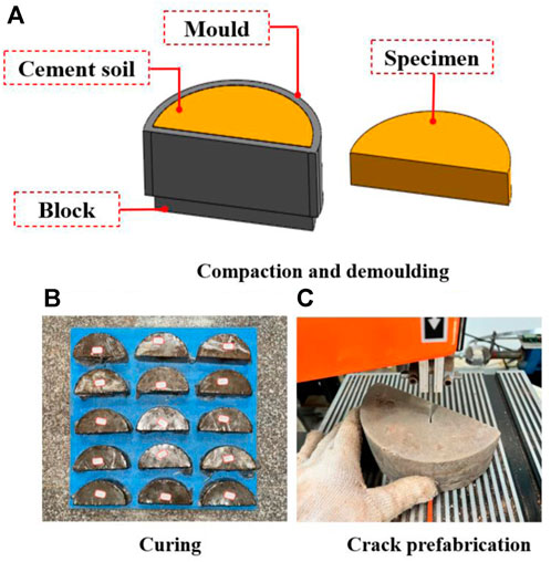
FIGURE 2. Schematic diagram of specimen preparation. (A) Mold diagram. (B) Sample curing.
To study the fracture failure mechanism of cement soil, different cement proportions and curing ages were considered in this experimental research. Specifically, the cement proportions were 5%, 10%, 15%, 20%, and 25%, and the curing ages were 1, 3, 5, and 7 days.
Table 1 shows the specific test schemes. Using the control variable method, Scheme 1 was designed to consider the effect of curing age, and Scheme 2 was designed to consider the effect of cement proportion. The crack angles of 0°, 10°, 20°, 30°, 40°, and 50° were selected, and the calculations were conducted based on the average peak load of 3 specimens. A total of 132 specimens were used.
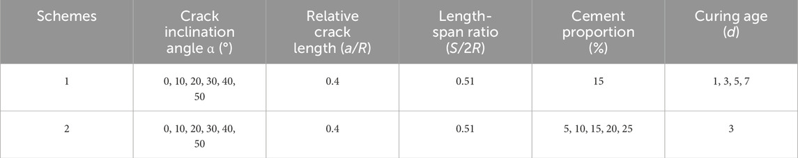
TABLE 1. Test schemes.
The tests were performed using chevron-notched SCB (CNSCB) specimens, and the loads were applied through three-point bending (Figure 3). According to the ISRM recommendation (Kuruppu et al., 2014), the length-span ratio S/2R was 0.51, and the relative length of the crack a/R was 0.4. The specimens in this study had a radius R of 75 mm and a thickness B of 50 mm. The loading rate was 0.6 mm/min.

FIGURE 3. Loading method for the CNSCB cement soil specimen.
The KI and KII values of the CNSCB specimens can be calculated with Eqs. 1, 2 (Ayatollahi and Aliha, 2007).
where KI is the mode I stress intensity factor, KII is the mode II stress intensity factor, F is the load, B is the specimen thickness, R is the specimen radius, a is the initial crack length, α is the initial crack angle, and YI and YII are dimensionless mode I and mode II stress intensity factors, respectively, which are related to the crack length-radius ratio, the initial crack inclination angle, and the span-radius ratio. The YI and YII values are shown in Figure 4.
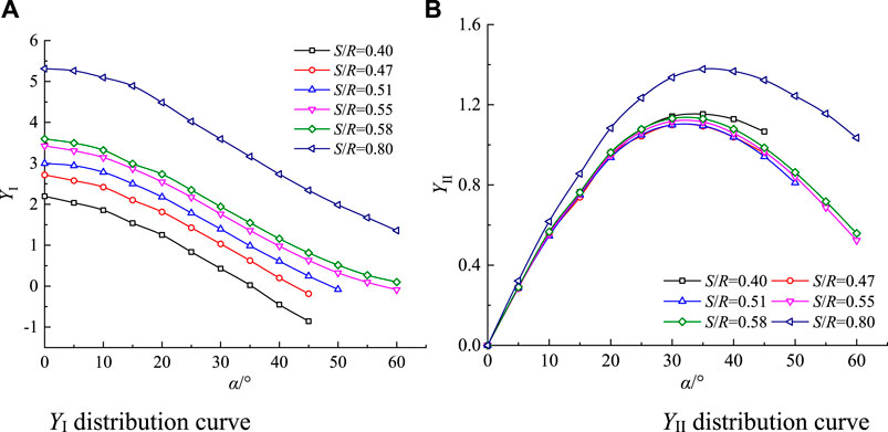
FIGURE 4. YI and YII distributions (Aliha et al., 2012).
Regarding the mixed mode I-II fractures in this study, KI > 0 and KII > 0 indicate the tensile shear stress state, and the combination relationship between KI and KII is generally expressed as Me.
Using specimens with a cement proportion of 15% and a curing age of 3 days as an example, the typical cement soil failure modes in the mixed mode I-II fracture tests are shown in Figure 5. As can be observed, the propagations begin at the tips of the initial cracks. The specimen with the initial crack inclination angle α of 0° shows a mode I fracture, and the propagation is along the initial crack direction. Specimens with α = 10°–40° show mixed mode I-II fractures. The specimen with α = 50° shows a mode II fracture. The crack propagation deviates from the direction of the initial crack. The greater the inclination angle of the initial crack, the more significant the deviation of the propagation direction. According to the sketch, the crack growth is not along a uniform, straight line but a jagged-like line. This is due to the inhomogeneity of the manually prepared specimens, manifested as many particle granules of varying strength that are bypassed by the propagating cracks. Meanwhile, the original propagation path is restored under the action of stress, and this back-and-forth process leads to jagged cracks.

FIGURE 5. Crack propagation patterns.
Figure 6A shows the variation patterns of the crack initiation angle, i.e., the angle between the initial crack and the extended crack, under different cement proportions. With the cement proportion being 5%–25%, the value of θ0 varies between 23.5° and 20.5° at the α of 10°. The value of θ0 varies between 42° and 39° at the α of 20°. The value of θ0 varies between 56.75° and 55° at the α of 30°. The value of θ0 varies between 71° and 67° at the α of 40°; the value of θ0 varies between 82.75° and 80.25° at the α of 50°. Overall, the variations of θ0 are within 4°, not exceeding the margin of error. Thus, it can be considered that the cement proportion has basically no effect on θ0. Therefore, the average values of θ0 were selected for the subsequent analysis, namely, 0°, 22.15°, 40.55°, 55.90°, 69.55°, and 81.05°, respectively.
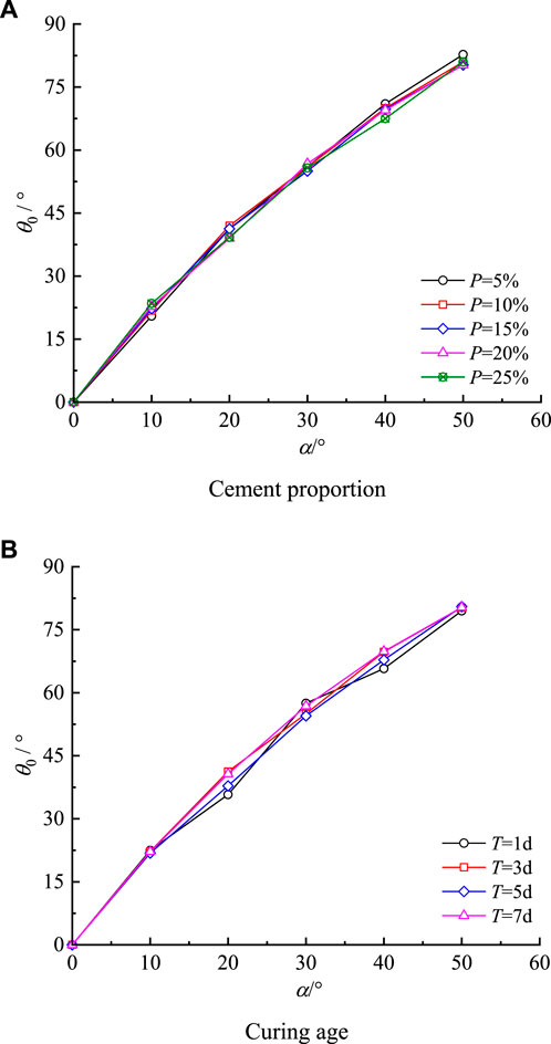
FIGURE 6. Crack initiation angle variation patterns.
Figure 6B shows the variation patterns of crack initiation angle under different curing ages. With the curing age being 1 day–7 days, the value of θ0 varies between 22.5° and 21.83° at the α of 10°; the value of θ0 varies between 41.25° and 35.75° at the α of 20°; the value of θ0 varies between 57.5° and 54.5° at the α of 30°; the value of θ0 varies between 69.83° and 65.75° at the α of 40°; the value of θ0 varies between 80.5° and 79.5° at the α of 50°. Overall, the variations of θ0 are within 5.5°, not exceeding the margin of error. Therefore, the curing age has basically no effect on θ0. Under different curing ages, the average values of θ0 are 0°, 22.19°, 38.88°, 55.96°, 69.83°, and 80.33°.
In summary, the effects of cement proportion and curing age. The mathematical relationship between its average values and Me is modeled as Eq. 4, and the curve is plotted as shown in Figure 7.
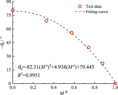
FIGURE 7. Curve of the relationship between θ0 and Me.
Figure 8 shows the relationship between the critical stress intensity factors K If and K IIf with the initial crack inclination angle α. With the gradual increase of the initial crack inclination angle, the critical stress intensity factor KIf gradually decreases while KIIf gradually increases, and KIf and KIIf also increase with the increase of cement proportion (Figure 8A) and curing age (Figure 8B). It can be observed that KIIf = 0 corresponds to mode I fracture, at which time KIf is the fracture toughness KIC of mode I fracture; KIf = 0 corresponds to pure mode II fracture, at which time KIIf is the fracture toughness KIIC of pure mode II fracture.
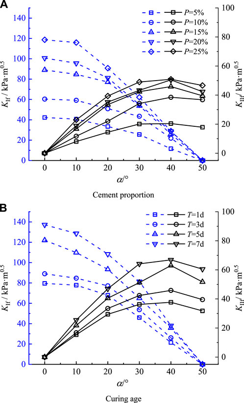
FIGURE 8. Variation patterns of KIf and KIIf.AB
Figure 9 shows the KIIf and KIf test value envelopes. Under different cement proportions, KIf and KIIf gradually increase with the increase of cement proportion, and the envelopes are more inward at lower cement proportions (Figure 9A). Under different curing ages, KIf and KIIf exhibit the same variation patterns as described above (Figure 9B).
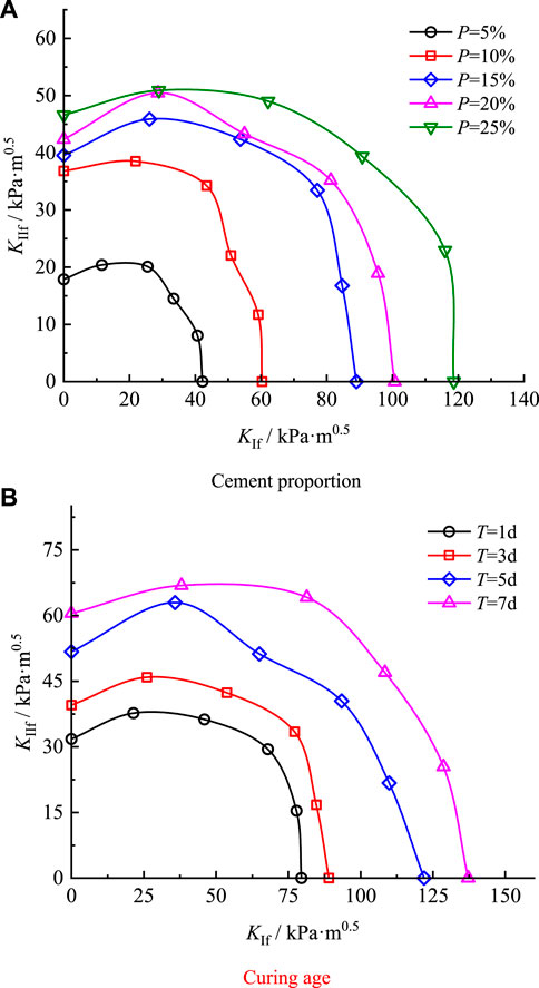
FIGURE 9. KIIf and KIf test value envelopes.
Figure 10 shows the KII/KIC and KI/KIC test value envelopes. It can be observed that the envelopes under different cement proportions intersect, and the KI/KIC and KII/KIC envelopes are close to basically stable within certain intervals. With KI/KIC = 0, the KII/KIC value varies between 0.61 and 0.39. Other than the obvious deviated points in the figure, the rest are between 0.39 and 0.45 (Figure 10A). The envelopes under different curing ages also intersect, and the KI/KIC and KII/KIC envelopes are close to basically stable within certain intervals. With KI/KIC = 0, the KII/KIC value varies between 0.44 and 0.40, which is within the 0.40 to 0.44 range (Figure 10B). The reason for the above phenomenon is that the soil-cement heterogeneity is more significant under the influence of factors such as material mixing degree, curing temperature and test conditions.
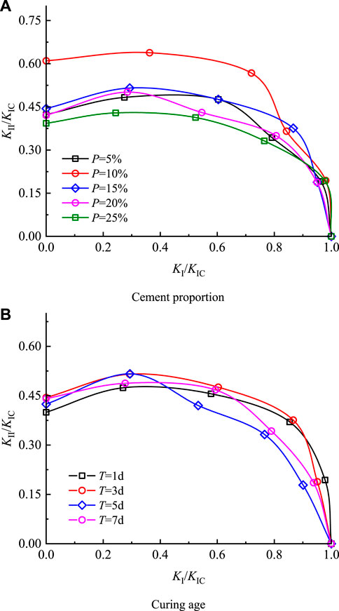
FIGURE 10. KII/KIC and KI/KIC test value envelopes.
Figure 11 shows the variation ranges of KII/KIC, KI/KIC, and crack initiation angle upon cement soil fracture failure obtained based on the test data. Based on the envelope variation intervals in Figure 11A, the upper and lower boundary functions of the KII/KIC value are fitted, i.e., the KII/KIC variation range of the cement soil with the cement proportion of 5%–25% and the curing age of 1 day–7 days. The variation range of θ0 under the KII/KIC and KI/KIC mixed stress states can be obtained based on Eq. 4, as shown in Figure 11B.
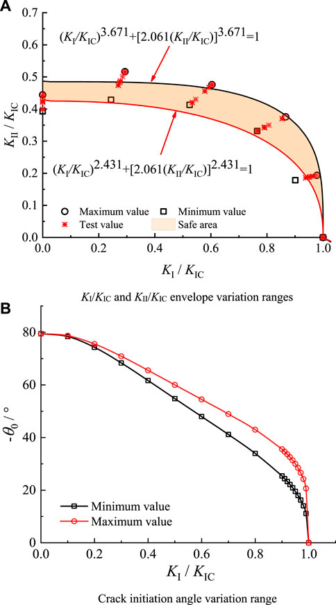
FIGURE 11. Parameter variation intervals upon cement soil failure.
Soil fracture analyses are often based on rock fracture criteria, such as the MTS criterion, G criterion, and S criterion mentioned above. Additionally, Wang et al. (Suits et al., 2006) adopted a circular fracture criterion in their analysis of Nuozhadu clay. Their equation is as follows:
As shown in Figure 12, the crack initiation angle upon pure mode II fracture is 70.53° according to the MTS criterion, which is significantly different from the θ0 in this study. In contrast, the KII/KIC obtained in this study is between 0.39 and 0.45, and those according to the MTS criterion are between 0 and 0.87, which is significantly not consistent. With the S criterion, both the crack initiation angle and the envelope are related to μ, which is set to 0.3 in this study. At this time, the crack initiation angle is 82.34°, and the KII/KIC value is between 0 and 0.96. According to Figure 12, the envelope is still above that of the MTS criterion. Compared with the two criteria above, the KII/KIC value based on the circular fracture criterion is above that of the S criterion, and the theoretical and test results are significantly different. Therefore, describing the cement soil fracture failure mechanism with classical fracture criteria has certain limitations.

FIGURE 12. Comparison between the test results and classical fracture criteria.
Considering the unsatisfactory results of the above classical fracture criteria, further analysis is conducted with the GMTS criterion. The stress field at the crack tip is as follows:
Compared to the MTS criterion, the T-stress is included, and the critical size rc of the crack tip micro-fracture zone is also taken into account. According to the GMTS criterion, the crack is initiated when the maximum tangential stress is reached. Then, we have:
Equation 8 can be normalized as:
As shown in Figure 13, the envelope of the MTS criterion is the outermost, while the envelope with a larger rc is more inward under the GMTS criterion. Under different cement proportions and curing ages, the test data envelopes are all far smaller than those under the MTS criterion, indicating the insufficiency of the MTS criterion in explaining the cement soil fracture mechanism. In contrast, the GMTS criterion is basically consistent with the test results. Other than the discrete points with large deviations, the test points are basically near the rc = 1 mm envelope.
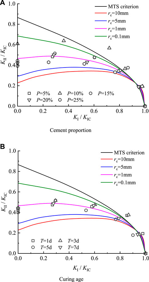
FIGURE 13. GMTS criterion and test values (KII/KIC and KI/KIC).
As shown in Figure 14, the test values of θ0 under different cement proportions and curing ages are in the ranges of theoretical curves rc = 1 mm to rc = 0.1 mm, indicating that the rc of the cement soil at this time is 0.1–1 mm. Considering the theoretical curves of KII/KIC and KI/KIC in Figure 13, the test values also fall near the rc = 1 mm curve. In summary, the KII/KIC and KI/KIC values and θ0 values of cement soil under the GMTS criterion are near the rc = 1 mm theoretical curve, indicating that the GMTS criterion can better describe the cement soil fracture failure mechanism.
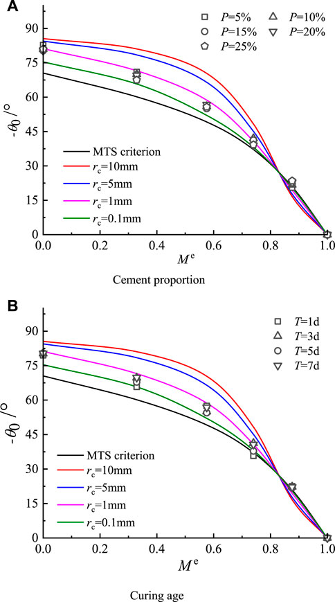
FIGURE 14. GMTS criterion and test values (θ 0).
Through inversion based on the θ0 test values, the theoretical value of rc is 0.3 mm–1.9 mm. In essence, adding cement and changing the curing age alter the brittleness of the material, and the rc corresponding to different cement proportions and curing ages should be different. Therefore, the rc value of cement soil should not be a fixed value but within a recommended range.
The following conclusions are reached through the mixed mode fracture tests on cement soil CNSCB specimens under different cement proportions (p = 5%, 10%, 15%, 20%, and 25%) and curing ages (T = 1, 3, 5, and 7 days):
1) Under different cement proportions and curing ages, the crack propagation in the CNSCB specimens is not a uniform, straight line but a jagged line.
2) KI and KII increase with the increase of cement proportion and curing age, and the area between the envelope and the axes also increases. The KII/KIC value is between 0.39 and 0.45 under different cement proportions and between 0.40 and 0.44 under different curing ages.
3) According to the test results, the traditional MTS criterion, S criterion, and G criterion have limitations in describing cement soil fracture failures, while the GMTS criterion can better describe cement soil fracture failures, with the test data consistent with the rc = 1 mm theoretical curve. The recommended range of rc for cement soil is 0.3 mm–1.9 mm.
The original contributions presented in the study are included in the article/Supplementary material, further inquiries can be directed to the corresponding author.
TL: Writing–review and editing. TD: Writing–original draft. HL: Investigation, Supervision, Writing–review and editing. BH: Conceptualization, Writing–review and editing. XY: Investigation, Visualization, Writing–review and editing. GL: Writing–review and editing.
The author(s) declare that no financial support was received for the research, authorship, and/or publication of this article.
Authors TL, HL, BH, and XY were employed by Guiyang Engineering Corporation Limited. Author GL was employed by China Construction Sixth Engineering Bureau Corp Ltd.
The remaining author declares that the research was conducted in the absence of any commercial or financial relationships that could be construed as a potential conflict of interest.
All claims expressed in this article are solely those of the authors and do not necessarily represent those of their affiliated organizations, or those of the publisher, the editors and the reviewers. Any product that may be evaluated in this article, or claim that may be made by its manufacturer, is not guaranteed or endorsed by the publisher.
Ajdani, A., Ayatollahi, M. R., and Silva, L. F. M. D. (2021). Mixed mode fracture analysis in a ductile adhesive using semi-circular bend (SCB) specimen. Theor. Appl. Fract. Mech. 112 (8), 102927. doi:10.1016/j.tafmec.2021.102927
Aliha, M. R. M., and Ayatollahi, M. R. (2010). Brittle fracture evaluation of a fine grain cement mortar in combined tensile-shear deformation. Fatigue and Fract. Eng. Mater. Struct. 32 (12), 987–994. doi:10.1111/j.1460-2695.2009.01402.x
Aliha, M. R. M., Ayatollahi, M. R., and Akbardoost, J. (2012). Typical upper bound-lower bound mixed mode fracture resistance envelopes for rock material. Rock Mech. Rock Eng. 45, 65–74. doi:10.1007/s00603-011-0167-0
Aliha, M. R. M., Behbahani, H., Fazaeli, H., and Rezaifar, M. (2014). Study of characteristic specification on mixed mode fracture toughness of asphalt mixtures. Constr. Build. Mater. 54, 623–635. doi:10.1016/j.conbuildmat.2013.12.097
Ayatollahi, M. R., and Aliha, M. R. M. (2007). Wide range data for crack tip parameters in two disc-type specimens under mixed mode loading. Comput. Mater. Sci. 38 (4), 660–670. doi:10.1016/j.commatsci.2006.04.008
Campbell, S., Ding, H., and Hesp, S. A. M. (2018). Double-edge-notched tension testing of asphalt mastics. Constr. Build. Mater. 166, 87–95. doi:10.1016/j.conbuildmat.2018.01.094
Chong, K. K. P. (2012). Fracture toughness testing of brittle materials using semi-circular bend (SCB) specimen. Eng. Fract. Mech. 91, 133–150. doi:10.1016/j.engfracmech.2012.01.013
Erdoga, F., and Sih, G. C. (1963). On the crack extension in plates under plane loading and transverse shear. J. Basic Eng. 85 (4), 519–525. doi:10.1115/1.3656897
Hussain, M. A., Pu, S. L., and Underwood, J. H. (1973). Strain energy release rate for a crack under combined mode I and mode II. Strain Energy Release Rate A Crack Under Comb. Mode I Mode II.
Kim, H., Wagoner, M. P., and Buttlar, W. G. (2008). Micromechanical fracture modeling of asphalt concrete using a single-edge notched beam test. Mater. Struct. 42 (5), 677–689. doi:10.1617/s11527-008-9412-8
Kuruppu, M. D., Obara, Y., Ayatollahi, M. R., Chong, K. P., and Funatsu, T. (2014). ISRM-suggested method for determining the mode I static fracture toughness using semi-circular bend specimen. Rock Mech. Rock Eng. 47 (1), 267–274. doi:10.1007/s00603-013-0422-7
Liu, X. M., Bian, Y. M., and Liang, Y. C. (2015). The volume strain energy density factor criterion for sharp V-notches under mixed-mode I and II. Appl. Mech. Mater. 782, 170–176. doi:10.4028/www.scientific.net/AMM.782.170
Rizvi, Z., Amin, A., Arp, J. C. C., and Wuttke, F. (2022). Fracture toughness mode I of glass fibers improved soil. Mater. Today Proc. 62, 3276–3281. doi:10.1016/j.matpr.2022.04.230
Smith, D. J., Ayatollahi, M. R., and Pavier, M. J. (2010). The role of T-stress in brittle fracture for linear elastic materials under mixed-mode loading. Fatigue and Fract. Eng. Mater. Struct. 24 (2), 137–150. doi:10.1046/j.1460-2695.2001.00377.x
Suits, L. D., Sheahan, T. C., Wang, J. J., Zhu, J. G., Chiu, C. F., and Chai, H. J. (2006). Experimental study on fracture behavior of a silty clay. Geotechnical Test. J. 30 (4), 100715–100719. doi:10.1520/GTJ100715
Sukontasukkul, P., and Jamsawang, P. (2012). Use of steel and polypropylene fibers to improve flexural performance of deep soil–cement column. Constr. Build. Mater. 29, 201–205. doi:10.1016/j.conbuildmat.2011.10.040
Sun, B., Zheng, Y., and Li, Z. (2020). Random beam lattice modeling method for catastrophic crack growth simulation of brittle-like materials. Constr. Build. Mater. 244, 118396. doi:10.1016/j.conbuildmat.2020.118396
Sun, D. L., Rao, Q. H., Wang, S. Y., Yi, W., and Shen, Q. q. (2021). A new mixed-mode fracture criterion of anisotropic rock. Eng. Fract. Mech. 2021 (4), 107730. doi:10.1016/j.engfracmech.2021.107730
Voottipruex, P., and Jamsawang, P. (2014). Characteristics of expansive soils improved with cement and fly ash in Northern Thailand. Geomechanics Eng. 6 (5), 437–453. doi:10.12989/gae.2014.6.5.437
Wagoner, M. P., Buttlar, W. G., and Paulino, G. H. (2005). Development of a single-edge notched beam test for asphalt concrete mixtures. J. Test. Eval. 33 (6), 1–13.
Xu, J. J., Zhang, H., Tang, C. S., Cheng, Q., Tian, B. g., Liu, B., et al. (2022). Automatic soil crack recognition under uneven illumination condition with the application of artificial intelligence. Eng. Geol. 296, 106495. doi:10.1016/j.enggeo.2021.106495
Yang, J., Chen, R., Zhang, Z., Zou, Y., Zhou, J., and Xia, J. (2023). Experimental study on the ultimate bearing capacity of damaged RC arches strengthened with ultra-high performance concrete. Eng. Struct. 279, 115611. doi:10.1016/j.engstruct.2023.115611
Yin, T., Wu, Y., Wang, C., Zhuang, D., and Wu, B. (2020). Mixed-mode I+II tensile fracture analysis of thermally treated granite using straight-through notch Brazilian disc specimens. Eng. Fract. Mech. 234, 107111. doi:10.1016/j.engfracmech.2020.107111
Zhang, Z., Jin, X., and Luo, W. (2019). Long-term behaviors of concrete under low-concentration sulfate attack subjected to natural variation of environmental climate conditions. Cem. Concr. Res. 116, 217–230. doi:10.1016/j.cemconres.2018.11.017
Zhang, Z., Pang, K., Xu, L., Zou, Y., Yang, J., and Wang, C. (2023). The bond properties between UHPC and stone under different interface treatment methods. Constr. Build. Mater. 365, 130092. doi:10.1016/j.conbuildmat.2022.130092
Zhou, L., Sarfarazi, V., Haeri, H., Ebneabbasi, P., Fatehi Marji, M., and Hassannezhad Vayani, M. (2021). A new approach for measurement of the fracture toughness using the edge cracked semi-cylinder disk (ECSD) concrete specimens. Mech. Based Des. Struct. Mach. 51 (5), 2896–2917. doi:10.1080/15397734.2021.1911667
Keywords: mixed mode I-II fracture, GMTS criteria, cement soil, cement proportion, curing age
Citation: Liu T, Du T, Lu H, Hu B, Yang X and Liu G (2024) The influence of cement proportion and curing age on the mixed mode I-II fracture characteristics of cement soil. Front. Mater. 10:1342249. doi: 10.3389/fmats.2023.1342249
Received: 21 November 2023; Accepted: 26 December 2023;
Published: 10 January 2024.
Edited by:
Zhongya Zhang, Chongqing Jiaotong University, ChinaReviewed by:
Wanli Guo, Nanjing Hydraulic Research Institute, ChinaCopyright © 2024 Liu, Du, Lu, Hu, Yang and Liu. This is an open-access article distributed under the terms of the Creative Commons Attribution License (CC BY). The use, distribution or reproduction in other forums is permitted, provided the original author(s) and the copyright owner(s) are credited and that the original publication in this journal is cited, in accordance with accepted academic practice. No use, distribution or reproduction is permitted which does not comply with these terms.
*Correspondence: Tiantian Du, MTg4NDU3OTI0OTdAMTYzLmNvbQ==
Disclaimer: All claims expressed in this article are solely those of the authors and do not necessarily represent those of their affiliated organizations, or those of the publisher, the editors and the reviewers. Any product that may be evaluated in this article or claim that may be made by its manufacturer is not guaranteed or endorsed by the publisher.
Research integrity at Frontiers
Learn more about the work of our research integrity team to safeguard the quality of each article we publish.