 Qin Yu-xin1
 Xiong Xin-meng
- 1Department of Intelligent Engineering, Zhengzhou University of Aeronautics, Zhengzhou, China
- 2Department of Materials, Zhengzhou University of Aeronautics, Zhengzhou, China
Introduction: Current research has mostly simplified CFRP components as isotropic media or homogenized them as anisotropic media, which fails to present the actual acoustic propagation behavior inside the CFRP components and restricts the accuracy of decoupling sound line tracking results and defect feature information.
Method: Based on clarifying the influence of fiber direction on the spatial distribution of CFRP elastic properties, this paper proposes an acoustic modeling method for CFRP multi-directional plates considering the coupling effect of multi-layer structure and elastic anisotropy.
Results: There are two main innovations: 1. The model is optimized using the Voigt representation method, which can quantitatively characterize the elastic anisotropy of any homogeneous material with a 6 × 6 elastic stiffness matrix containing 21 independent elastic constants. In this paper, the elastic stiffness matrix only includes five independent elastic constants; 2. Finite element simulation is used to analyze the propagation rules of ultrasonic waves inside CFRP and compare the detection methods with or without sound coupling layer.
Discussion: The acoustic characteristics of the sound coupling layer are changed to find the optimal coupling method, reduce the refraction of ultrasonic waves in the specimen layer, and make the sound line path more accurate.
1 Introduction
Carbon Fiber Reinforced Plastics (CFRP) is a structural material composed of high-strength carbon fibers as the reinforcing phase and resin as the matrix. Carbon fibers, as the main load-bearing part of CFRP, are continuous filaments with a diameter of approximately 5–10 μm, made from polyacrylonitrile and asphalt filaments through a carbonization process. Carbon fibers possess characteristics such as lightweight, high strength, high modulus, and stable chemical properties. CFRP, with its high specific strength, high specific stiffness, good fatigue and corrosion resistance, as well as ease of large-scale molding, has gained attention in the aerospace field. It is gradually replacing traditional metal materials as load-bearing components in aircraft structures, playing a vital role in achieving lightweight, high-performance, and cost-effective aircraft structures. Due to factors such as manufacturing technology and cost control, the application of composite materials in civil aircraft has been limited to around 10% (HUANG et al., 2023). er, with the continuous improvement of advanced composite manufacturing technolHowevogy, their application scope in civil aircraft has gradually expanded from fairings, elevators, rudders, spoilers, and secondary load-bearing components to primary load-bearing components such as central-wing box and fuselage (LIU et al., 2023). Defects in CFRP components are inevitable during manufacturing and service stages, mainly due to the diversity of material compositions, complexity of structures, and instability of manufacturing processes.
Nondestructive Testing (NDT) is based on the premise of not compromising the functional performance of the object being tested. It applies various physical principles and chemical phenomena to effectively inspect and test various engineering materials, components, and structures, in order to assess their continuity, integrity, safety, reliability, and certain physical properties. This includes detecting the presence of defects in the material or component, and assessing the shape, size, orientation, distribution, and internal contents of these defects. Furthermore, when there are no significant defects that impact usage within the object being tested, NDT can also provide information on the organization and distribution of materials, as well as stress states (CAI et al., 2023).
To simulate the acoustics of CFRP (Carbon Fiber Reinforced Polymer) components, it is necessary to understand their internal microstructure. The acoustic characteristics of CFRP components are complex and mainly influenced by the coupling effects of three factors: complex geometric shape, multilayer structure, and elastic anisotropy. Therefore, the key to acoustic modeling of CFRP components lies in clarifying the individual effects of these three factors and their coupling mechanisms. However, existing research work often simplifies CFRP components as either isotropic media or homogenizes them as anisotropic media. For instance, Willmann et al. conducted health monitoring of CFRP laminates under cyclic loading by assuming isotropic specimen parameters based on vibration-acoustic modulation measurements (Erik et al.). Morokov et al. combined high-frequency ultrasound with a long-focal-length transducer beam acoustic microscope and mechanical testing machine to visualize the evolution of damage inside isotropic CFRP laminates (Egor et al., 2022). Qin et al. characterized impact fatigue damage in CFRP composites using nonlinear acoustic resonance methods, assuming CFRP materials as isotropic media (Wei et al., 2020). Zhang et al. performed finite element analysis by homogenizing CFRP as an anisotropic medium to simulate fatigue phenomena in specimens (Zhang et al., 2020). These studies share a common limitation, as they fail to accurately simulate the actual sound wave propagation behavior inside CFRP components, which restricts the accuracy of guided wave results and defect characterization information.
In this paper, a novel acoustic modeling method is proposed that takes into account the microstructural characteristics of typical CFRP components, as well as the coupling effects of factors such as multilayer structure and elastic anisotropy. By utilizing this finite element acoustic simulation, it is possible to reveal the influence of the acoustic characteristics of CFRP components on the behavior of ultrasonic wave propagation, analyze the causes of interference signals, and provide theoretical support and a model foundation for subsequent research.
2 Acoustic modeling of CFRP plates
2.1 CFRP plate specimens
To investigate the properties of aerospace CFRP components, CFRP multidirec-tional plate specimens were prepared, as shown in Figure 1. These specimens were made by stacking carbon fiber/epoxy resin prepregs and then solidifying them through hot pressing. Detailed information about the specimens can be found in Table 1.
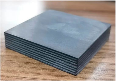
FIGURE 1. CFRP plate sample.
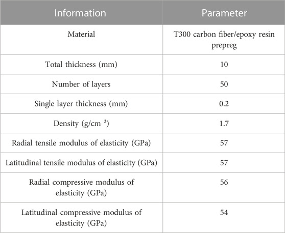
TABLE 1. CFRP sample information.
2.2 Principles of CFRP plate acoustic modeling
The acoustic model established in this article needs to accurately describe the spatial distribution of the acoustic characteristics of CFRP components, in which elastic characteristics are the most critical factor. It can be determined that the local elastic characteristics of CFRP components are directly related to their fiber direction. Taking into account the variation of fiber orientation with the ply in CFRP multidirectional plates, this paper establishes an acoustic model using Bond transformation theory. This model is based on the layer information obtained from metallographic observations (layer quantity, layer order, and single layer thickness), as well as the measured elastic stiffness matrix values of CFRP unidirectional fiber layers. By considering the coupling effect between multi-layer structures and elastic anisotropy, this acoustic model can accurately describe the acoustic characteristics of CFRP components.
2.2.1 Anisotropic elastic waves
CFRP material has the directional arrangement characteristics of high-strength carbon fibers in the resin matrix, which determines that it is essentially an elastic anisotropic medium. For this elastic anisotropic medium, the theory of sound propagation still applies. This article assumes that sound waves propagate in an infinite elastic anisotropic medium, following the Christophel equation:
Where:
Where:
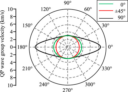
FIGURE 2. Spatial distribution of quasi longitudinal wave (qP wave) group velocity at different angles of carbon fiber layer.
2.2.2 Multidirectional plate acoustic modeling method and optimization
According to the theory of sound propagation, it is known that the distribution of the speed of sound in a material is closely related to its elastic properties (Yang et al., 2023). By using the Voigt representation method, the elastic stiffness matrix can be used to quantitatively describe the elastic anisotropy of any homogeneous material, and this elastic stiffness matrix is a symmetric matrix that contains up to 21 independent elastic constants:
A schematic diagram of the microstructure metallography image of the cross-section of CFRP layups based on the unidirectional fiber orientation is presented in Figure 3, which is the focus of this study. Observations reveal that within the
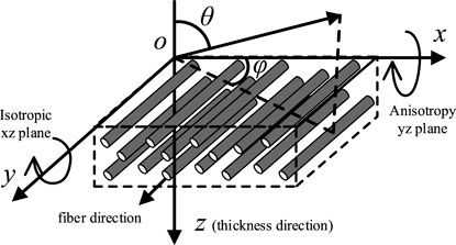
FIGURE 3. Schematic diagram of metallographic photos of the cross-sectional microstructure of CFRP layer.
For a CFRP plate, there are a total of
In the current 0-xyz coordinate system, the elastic stiffness matrix for the 0° layer can be determined using Eq. 5. Other layers with different fiber orientation angles can be considered as obtained by rotating the 0° layer around an axis by the corresponding angle. Therefore, we can calculate the local elastic stiffness matrix at any point
Where
3 Ultrasonic finite element simulation
In this paper, the popular and widely used finite element analysis software COMSOL was employed, which can effectively solve coupling problems among physical fields and has high accuracy and powerful post-processing capabilities (Li, 2022). Therefore, in this study, the transient problem of ultrasonic propagation in different media was simulated using the COMSOL finite element software. This approach ensures the reliability and accuracy of the research results.
This experiment focused on the CFRP flat plate specimen shown in Figure 1, with particular emphasis on the following issues.
(1) Under the experimental conditions corresponding to Figure 1, the excitation probe directly contacted the surface of the CFRP multidirectional plate, allowing the ultrasonic wave to directly enter the interior of the CFRP. At this time, the main factors affecting the behavior of ultrasonic wave propagation are the anisotropic acoustic velocity distribution of CFRP and the acoustic mismatch of the interlayer interfaces. By studying the coupling effect between these two factors and their impact on the propagation behavior of incident ultrasonic waves, a foundation can be provided for the subsequent analysis of acoustic propagation behavior under more complex experimental conditions.
(2) In order to ensure effective acoustic energy transmission, direct contact method is rarely used for ultrasonic testing in engineering practice. Typically, an acoustic coupling medium is filled between the transducer and the CFRP component. This testing method not only protects the transducer from wear during sliding scanning but also avoids the blind zone caused by the pulse width of the transducer’s initial pulse. Choosing different acoustic coupling media will change the acoustic matching at the “coupling layer/CFRP" interface, thereby affecting the reflection and refraction behavior of ultrasonic waves at the interface, and consequently influencing the propagation behavior of ultrasonic waves inside the CFRP. In this paper, a comparative analysis was conducted using the two most commonly used acoustic coupling methods in engineering practice, namely, immersion in water and coupling using an organic glass wedge. The influence of introducing an acoustic coupling layer and the changes in its acoustic characteristics on acoustic propagation behavior were studied, providing guidance for the selection of acoustic coupling materials.
The simulation software used in this study is COMSOL Multiphysics 6.0. In the model, the axis is parallel to the 0° fiber direction and the axis is parallel to the thickness direction of the specimen. The solid part (including the CFRP specimen and the organic glass coupling wedge) is modeled using the Structural Mechanics module, while the liquid part (water coupling layer) requires the use of the Acoustic Pressure module. To ensure continuous propagation of the ultrasonic wave between the solid and liquid, a “Multiphysics Coupling Boundary" is defined as the interface between the solid and liquid. The transducer is placed horizontally at the upper boundary of the model. To simulate the excitation of the ultrasonic wave in the time domain, the time-dependent change in stress is described by applying a transient stress boundary condition in a specific direction.
In the equation,
Here, c represents the minimum sound velocity in the acoustic propagation medium of the model, and Δs is the maximum mesh size in the model. In this study, we set ΔT = 1/(25
In order to maintain consistency with the ultrasonic wave excitation time-domain signal used in practical applications, the following parameter values were chosen in this study:
The model mainly includes three types of materials, namely, CFRP, water, and organic glass, with their minimum longitudinal sound velocities being 2,968.5 m/s, 1483.4 m/s, and 2,675.8 m/s, respectively. Based on the finite element calculation parameter selection principle mentioned above, the maximum mesh size and calculation time step of each model at the current ultrasonic detection frequency can be calculated. Figure 4 shows the finite element model of the CFRP specimen studied in this article.
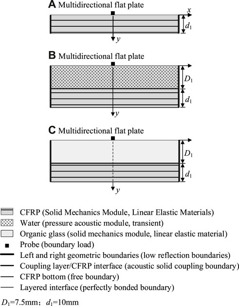
FIGURE 4. Finite element models of CFRP specimens: (A) direct contact; (B) immersed in water; (C) coupled with organic glass.
4 Simulation and analysis of the sound propagation behavior of CFRP multidirectional plate
In this section, a pulsed probe with a frequency of 10 MHz was used to inspect the specimen, with the x-axis and y-axis aligned parallel to the 0° fiber direction and the thickness direction of the sample, respectively. The solid part of the model, including the CFRP specimen and the organic glass coupling wedge, was simulated using the structural mechanics module. The liquid part, on the other hand, required the use of the acoustic pressure module to simulate the water coupling layer. To ensure the continuity of ultrasonic wave propagation between the solid and liquid, the interface between the two was defined as a “multi-physics coupling boundary". Additionally, the probe was horizontally placed along the upper boundary of the model.
Figure 5A shows the simulated snapshots of the wavefield when performing direct contact inspection on a CFRP multidirectional plate. Figure 6 displays the ultrasonic wavefront of the CFRP multidirectional plate test sample model. It can be observed from Figure 5 and Figure 6 that the incident wave exhibits multiple modes on the wavefront, with the front-most qP wavefront being approximately elliptical. This indicates that although the multidirectional plate is composed of fibers laid in different directions, it exhibits a relatively strong elastic anisotropy overall. This anisotropy is manifested by the minimum sound velocity in the thickness direction of the multi-directional CFRP plate, which rapidly increases as the deviation angle from the propagation direction to the thickness direction increases. As the wavefront passes through the region, noise echoes become evident. The noise level in the local region is lower, while the noise amplitude in the left and right directions near the probe significantly increases. This is because the fiber layers in different directions in the multi-directional CFRP plate have the same acoustic characteristics in the thickness direction, thus no reflection and refraction occur at the layer interface, avoiding energy loss and noise generation. However, as the angle of deviation from the propagation direction to the thickness direction increases, the mismatch of acoustic characteristics at the layer interface intensifies, leading to higher noise generated by the ultrasound waves propagating along that direction due to interface reflections.
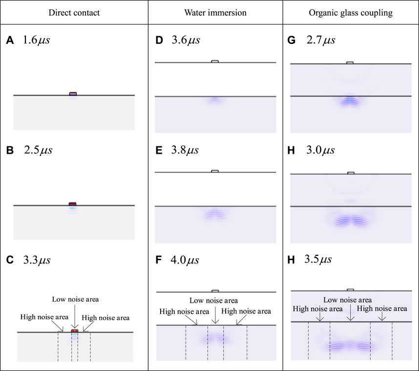
FIGURE 5. Wavefield snapshot of CFRP multi-directional flat plate specimen model (probe is a small rectangle above): (A–C) Direct contact (D–F) Water immersion (G–I) Organic glass coupling.
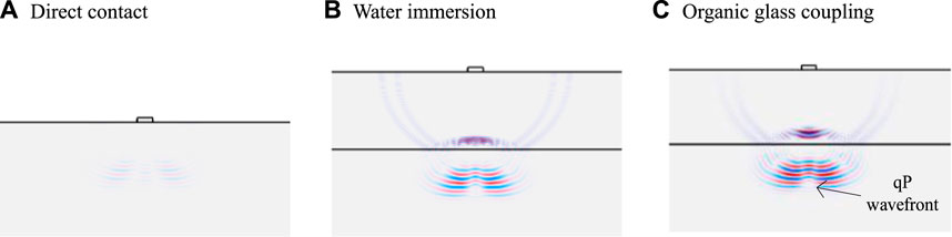
FIGURE 6. Ultrasonic Wave Front of CFRP Multidirectional Plate Sample Model (Probe is a Small Rectangle Above).
From the observations in Figure 5 (c), (f), (i) and Figure 6, it can be seen that with the addition of the coupling layer, the lateral range of the low-noise region between the probe and the multi-directional CFRP plate increases, no longer limited to the local area directly under the probe. Additionally, under direct contact conditions, as the lateral distance from the probe increases, the amplitude of the wavefront energy decreases rapidly. However, in the presence of the coupling layer, the decreasing trend of the energy amplitude slows down when the wavefront can cover a wider lateral range. This is because although the shapes of the wavefronts are similar in both conditions, approximating an elliptical shape, there are differences in the direction of sound propagation. Under direct contact conditions, the incident point of the ultrasonic wave is located at the position of the probe, so the ultrasound wave can only reach further lateral positions when the propagation direction deviates significantly from the thickness direction. In the presence of the coupling layer, the ultrasound waves emitted from the probe at a smaller angle deviation from the thickness direction can reach further lateral positions inside the coupling layer and enter the “coupling layer/CFRP" interface at a smaller angle. This means that the degree of reflection and refraction at the layer interface is weakened, resulting in a reduction in the amplitude of the layer interface echo noise and the degree of refracted sound energy loss. Considering that the elastic anisotropy of CFRP weakens as it approaches the thickness direction, the speed difference of the wavefront propagating in different directions also decreases under the presence of the coupling layer.
Figure 5 (e) and (h) respectively show that when the ultrasound wave propagates to approximately the same depth inside the CFRP with the same thickness of the coupling layer, the difference in lateral propagation distance of the wavefront is more significant under water immersion conditions. This indicates that at the “water/CFRP" interface, the deflection of the ultrasound wave is more pronounced compared to the “organic glass/CFRP" interface. This is because the sound velocity of organic glass (2,675.8 m/s) is closer to that of CFRP (
In order to illustrate the impact mechanism of the acoustic coupling layer on the phased array ultrasonic imaging quality of CFRP multi-directional plate specimens and to verify the optimal choice of coupling with organic glass, three experimental conditions were conducted: direct contact, water immersion, and coupling with organic glass, corresponding to Figure 5. Using the ray tracing method, the ray paths between the probe at the starting point and the target point located at coordinates (7, 5.9) inside the CFRP were calculated, as shown in Figure 7. It should be noted that the segmented ray paths inside the isotropic acoustic coupling layer are straight lines connecting the probe and the incident point on the sample surface. Only the segmented ray paths inside the sample are shown here for clarity. It can be observed that compared to the direct contact condition (Figure 7A), both water immersion (Figure 7B) and the use of the organic glass coupling layer (Figure 7C) can cause the incident point to move to the right, with the latter resulting in a larger displacement. There are two main reasons for this result: Firstly, the introduction of the coupling layer allows the ultrasound to propagate within the layer and reach a position closer to the target point along the horizontal direction. When the ultrasound is incident at the “coupling layer/CFRP" interface, it can continue to propagate towards the target point without requiring a large angle of refraction. Additionally, organic glass has acoustic properties closer to CFRP compared to water, which can effectively reduce the refraction of ultrasound at the sample surface. This change in sound propagation behavior at the “coupling layer/CFRP" interface results in a decrease in the angle deviation of the incident ultrasound with respect to the normal direction of the sample surface as it passes through each layer, thereby reducing the influence of CFRP anisotropy and decreasing the level of structural noise generated by the layer interfaces.

FIGURE 7. Illustrates the ray path of the probe from the starting point to the target (7, 5.9).
5 Conclusion
Based on the investigation of the spatial distribution of elastic properties in CFRP influenced by fiber orientation, this paper proposes an acoustic modeling method for laminated CFRP plates considering multi-layer structure and elastic anisotropy coupling. The method improves upon conventional approaches to reduce computational complexity and improve accuracy. Based on finite element simulation, the propagation characteristics of ultrasound waves inside CFRP are analyzed, and a comparison is made between the detection methods with and without a coupling layer, as well as the variations in the acoustic properties of the coupling layer.
In addition to transmitting sound energy, variations in the coupling layer can also alter the acoustic matching at the “coupling layer/CFRP" interface. Due to this effect, the incidence angle distribution of ultrasound waves at the “coupling layer/CFRP" interface changes, directly influencing the degree of tilt of the incident ultrasound wave when passing through the acoustically mismatched ply interface. Compared to direct contact conditions, the use of a coupling layer, especially when selecting a material with acoustic properties similar to CFRP as the coupling layer, can mitigate the adverse effects of CFRP’s complex acoustic properties on sound propagation, reduce the amplitude level of structure noise caused by layer interface reflections, and thereby obtain higher-quality incident wavefronts.
Data availability statement
The original contributions presented in the study are included in the article/supplementary material, further inquiries can be directed to the corresponding author.
Author contributions
QY-x: Writing–original draft. XX-m: Writing–review and editing. ZW-l: Writing–review and editing.
Funding
This work was supported in part by the Scientific Research Team Plan of Zhengzhou University of Aeronautics (No. 23ZHTD01005), in part by the Scientific and Technological Key Project of Henan Province (No 232102210151), in part by the Scientific and Technological Key Project of Henan Province (No 222102320191), in part by the Scientific and Technological Key Project of Henan Province (No 212102210514), in part by the Training Program for Young Scholar of Henan Province for Colleges and Universities (No. 2020GGJS172), in part by the Program for Science & Technology Innovation Talents in Universities of Henan Province (No. 22HASTIT020), in part by Henan Center for Outstanding Overseas Scientists (No. GZS2022011), in part by Henan Province Collaborative Innovation Center of Aeronautics and Astronautics Electronic Information Technology, in part by Henan Province Special and Urgent Subject Group of Aeronautical and Astronautical Intelligent Engineering, in part by Henan Key Laboratory of General Aviation Technology.
Conflict of interest
The authors declare that the research was conducted in the absence of any commercial or financial relationships that could be construed as a potential conflict of interest.
Publisher’s note
All claims expressed in this article are solely those of the authors and do not necessarily represent those of their affiliated organizations, or those of the publisher, the editors and the reviewers. Any product that may be evaluated in this article, or claim that may be made by its manufacturer, is not guaranteed or endorsed by the publisher.
References
Cai, S., Song, J., Wang, Y., Chen, D., Deng, K., Tang, Y., et al. (2023). Optimization of pulsed laser ablation of CFRP materials. Laser Technol. 1-9. [2023-10-17].
Egor, M., Sergey, T., and Vadim, L. (2022). In situ high-resolution ultrasonic visualization of damage evolution in the volume of quasi-isotropic CFRP laminates under tension. Compos. Part B, 247. doi:10.1016/J.COMPOSITESB.2022.110360
Erik, W., Benjamin, B., Moritz, S., Horst, R. M., and Bodo, F. (2023). Health monitoring of CFRP laminates under cyclic loading via vibro-acoustic modulation based measurements. Compos. Struct., 308. doi:10.1016/J.COMPSTRUCT.2023.116696
Guo, X. (2022). Research on ultrasonic detection and full matrix imaging of multilayer discontinuous impedance structures. Taiyuan, China: North University of China.
He, X., Jin, S., and Lin, Li (2018). Recursive quantitative analysis of ultrasonic backscatter signals for non-destructive characterization of CFRP pore distribution simulation . J. Compos. Mater. 35 (10), 2753–2759. doi:10.13801/j.cnki.fhclxb.20180105.001
He, X. (2018). Nondestructive characterization of CFRP porosity by recursive quantitative analysis of ultrasonic backscattered signals. Dalian: Dalian University of Technology.
Huang, B. (2022). Study on 6061Al/CFRP welding, rivet and glue composite connection technology. Dalian: Dalian University of Technology.
Huang, C., Jiang, H., Wang, X., Xu, Q., and Han, W. (2023). Improvement of anisotropic guided filtering for clear field microscopic image [J/OL. Progress in Laser and Optoelectron. 1-19. [2023-10-17].
Li, B. (2022). Research on Anisotropic Media decoupling approximate acoustic forward modeling and Inverse time migration. Changchun, China: Jilin University.
Li, X., and Yan, J. (2021). Simulation and analysis of wave field azimuthing characteristics in fractured media based on Bond transform. Prog. Geophys. 36 (05), 2034–2044. doi:10.6038/pg2021EE0401
Liu, Z., Zheng, L., Liu, X., and Tang, L. (2023). Nonlinear ultrasonic simulation analysis of micro-crack detection and location. Cem. Carbide 40 (03), 209–2017. doi:10.3969/j.issn.1003-7292.2023.03.006
Wei, Q., Zhu, L., Zhu, J., Zhuo, L., Hao, W., and Xie, W. (2020). Characterization of impact fatigue damage in CFRP composites using nonlinear acoustic resonance method. Compos. Struct. 253, 112804. (prepublish). doi:10.1016/j.compstruct.2020.112804
Xu, S. (2014). Research on numerical simulation method of acoustic anisotropic medium. Changchun, China: Jilin University.
Xu, L., Pan, Q., Wang, C., Gu, J., Wu, J., and Liu, J. (2015). Ultrasonic testing of the bonding quality of carbon fiber-aluminum multilayer structures. Meas. Technol. 35 (03), 33–35+69. doi:10.11823/j.issn.1674-5795.2015.03.08
Yang, H., Yang, Z., Yang, L., Single, M., Lin, K., and Wu, Z. (2023). Research progress of ultrasonic damage detection and imaging methods for carbon fiber Composites materials [J]. Chin. J. Compos. 40 (08), 4295–4317. (in Chinese). doi:10.13801/j.cnki.fhclxb.20230318.001
Yang, H. (2017). Study on interface debonding defects of multi-layer bonding structures based on ultrasonic detection. Sichuan, China: Southwest Jiaotong University.
Zhang, Q. (2020). Characteristics of seismic wave propagation in transversely isotropic media and numerical simulation of wave equations [D]. Beijing: China University of Mining and Technology. doi:10.27624/d.cnki.gzkbu.2020.000130
Zhang, R. H., Shi, K. Y., He, J. J., Gao, P. J., et al. (2020). Modeling and eddy current non-destructive testing of homogenized plain weave carbon fiber reinforced composites. J. Tianjin Univ. Technol. 39 (05), 61–66. doi:10.3969/j.issn.1671-024x.2020.05.010
Zheng, S., Lu, M., Wang, J., Luo, Y., and Dong, J. (2019). Ultrasonic detection method of disadhesion defects in multilayer structures. J. Appl. Acoust. 38 (01), 134–141. (in Chinese). doi:10.11684/j.issn.1000-310X.2019.01.018
Keywords: acoustic modeling, acoustic propagation behavior, CFRP components, multi-layer structures, elastic anisotropy
Citation: Yu-xin Q, Xin-meng X and Wen-li Z (2023) Optimization study of finite element simulation based on multi-layer structure and anisotropic CFRP. Front. Mater. 10:1288846. doi: 10.3389/fmats.2023.1288846
Received: 05 September 2023; Accepted: 11 October 2023;
Published: 07 November 2023.
Edited by:
Veerappan Mani, King Abdullah University of Science and Technology, Saudi ArabiaReviewed by:
Kailu Xiao, Texas A and M University, United StatesLin Wei, Lam Research, United States
Copyright © 2023 Yu-xin, Xin-meng and Wen-li. This is an open-access article distributed under the terms of the Creative Commons Attribution License (CC BY). The use, distribution or reproduction in other forums is permitted, provided the original author(s) and the copyright owner(s) are credited and that the original publication in this journal is cited, in accordance with accepted academic practice. No use, distribution or reproduction is permitted which does not comply with these terms.
*Correspondence: Xiong Xin-meng, MTgwNTk2NTUyOEBxcS5jb20=