 Wang Jun1,2
 Zhu Chuangen
94% of researchers rate our articles as excellent or good
Learn more about the work of our research integrity team to safeguard the quality of each article we publish.
Find out more
ORIGINAL RESEARCH article
Front. Mater., 05 December 2023
Sec. Structural Materials
Volume 10 - 2023 | https://doi.org/10.3389/fmats.2023.1285551
This article is part of the Research TopicStructural Applications of Concrete with Recycled Solid Wastes and Alternatives for CementView all 9 articles
The bearing property and deformation failure law of the CFST circular arch were investigated in order to provide direction for the optimization of the concrete-filled steel tube (CFST) support. The flexural bearing capacity test of the 194 mm × 10 mm CFST was performed initially in this study. It was primarily explored how bearing capacity and deformation of circular arches were affected by the slip of the arch foot and anti-bending strengthening, and the neutral layer migration rule and anti-bending strengthening mechanism of circular arches were examined. The bearing performance of the circular arch under the condition of the concentrated load of the vault and the usual uniform load of the entire span is then simulated in an orthogonal test by numerical simulation in order to extend the experimental investigation. The effect of variables including the steel tube’s outer diameter, thickness, slip of the arch foot, and the ratio of the arch rise to span on the bearing capacity of the circular arch is examined. The study demonstrates that under focused stress on the arch top or full-span normal uniform loading, the arch foot slip is the most important element impacting the CFST support’s bearing capacity. In steel tubes with the same outer diameter and wall thickness, the vector span ratio has a bigger influence than anti-bending strengthening. When the span ratio is the same, the influence of the outer diameter and wall thickness are equal and outweigh the influence of bending strengthening. The circular arch with an outside diameter of 168 mm, a wall thickness of 10 mm, and a rise-span ratio of 0.207 has the best performance characteristics under the influence of concentrated load, and the ultimate failure mechanism is local waist drum deformation failure. Based on the aforementioned study findings, the circular CFST support’s buckling deformation and drum deformation are examined, and a composite support consisting of “anchor net spray + CFST support” is directed for the north three deep track downhill of Yangcheng Coal Mine. Two failure types expose the failure mechanism and provide a technique for optimization. The support had contributed to the circular CFST arc arch’s best bearing performance in the event of waist drum deformation and failure.
The concrete-filled steel tube’s (CFST) circular arch may convert an external load into an axial force acting on the arch, maximizing the benefits of the material’s high axial bearing capacity and enabling CFST support with a circular arch. High carrying capacity is a benefit of the support (Gao et al., 2010; Li et al., 2017). It is being used frequently in deep roadway support and has produced positive supportive results (Li et al., 2013; He et al., 2015; Liu et al., 2018; Wang et al., 2020). However, there are still some issues with drum deformation failure or buckling deformation failure of steel tube supports that are filled with concrete in real-world engineering applications. Studying the causes of failure can help to direct and improve the support design of steel tube supports that are filled with concrete.
Relevant academics both domestically and internationally have conducted in-depth research on concrete filled steel tubular circular arches. Mark Andrew Bradfor and Yonglin Pi et al. (Bradford et al., 2011; Pi et al., 2011) studied the in-plane time-varying performance, buckling behavior, and various factors caused by shrinkage and creep of core concrete under radial uniform load through theoretical analysis and numerical simulation. Wang et al. (2011a,b) investigated the in-plane nonlinear stability carrying capacity of CFST circular arch under uniform load and the impact of core concrete shrinkage and creep, rise-span ratio, and arch stability outside of plane. The mechanical characteristics and stability of the CFST circular arch structure under concentrated load were examined and assessed by Luo et al. (2015). Through numerical simulation, Han et al. (2020) investigated the bearing behavior of the CFST circular arch’s structural performance during an in-plane instability failure. They also looked at the effects of concrete strength, rise-span ratio, and other variables. Through theoretical research, laboratory testing, and numerical simulation, Lu and Sun. (2020) established the stress model of CFST circular arch, which offers a theoretical foundation for the design of subterranean engineering support. Shan et al. (2018) studied the effects of the arc arch under six-point equivalent loading, such as the vector span ratio and steel fiber content, on the mechanical properties of the specimen and discovered the reasons for the local instability failure of the component through laboratory tests, numerical simulation, and theoretical analysis. Through laboratory testing and theoretical research, Zhang et al. (2017) identified the circular arch’s failure mode and came to the essential requirement for the circular arch’s overall instability. Through laboratory testing and numerical simulations, Liu et al. (2018) investigated the impact of rise-span ratio on the failure characteristics and ultimate bearing capacity of CFST circular arches and revealed the compression failure mechanism of steel tubes and core concrete. Yan et al. (2018) examined the creep and bearing capacity of a circular fly ash-filled CFST arch and the mechanism by which internal structural forces affect the height of the neutral layer. Through laboratory tests, Hu et al. (2020) investigated the in-plane stability of circular CFST arches with various rise-span ratios under a concentrated five-point symmetric load.
The bearing capabilities and stability of the circular arch of CFST were primarily examined in the aforementioned literature. However, there are few studies on the deformation and failure analysis of the circular arch waist, and the study on the compression-bending performance of the CFST circular arch under the circumstances of anti-bending strengthening or sliding of the arch foot is not sufficiently thorough. Based on the experimental study on the bearing capacity of circular arches, the experimental study is enlarged by numerical simulation with the goal of addressing the yield failure problem of CFST circular arches. Different loading forms, steel tube wall thickness, rise-span ratio, anti-bending strengthening of the arch, and slip of the arch foot were evaluated as effect variables. The bending failure mechanism of the CFST circular arch was discovered, and this information was used to direct the structural optimization of the CFST circular support in the deep highway support.
The CFST tube support, which is often split into four circular arch sections, is a frequent supporting structure in deep roadways (Figure 1). In order to conduct experimental study, the 1/4 circular arch was removed. The bearing performance of the structure under centralized loading and full-span uniform loading of the arch was then examined.
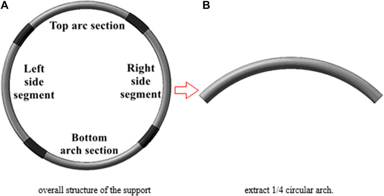
FIGURE 1. Extraction diagram of circular concrete-filled steel tube support test members.
Made of seamless steel tubing of grade 20# measuring 194 mm by 10 mm, the circular arch is constructed. The two ends are flattened and treated perpendicular to the arch’s axis. Concrete that hardens quickly, type C40, is poured within the steel tube. According to the diameter of the anti-bending round steel, six specimens were created. Steel rounds with diameters between 40 and 60 were used to weld the circular arch. The dimensions are depicted in Figure 2, and the parameters are presented in Supplementary Table S1. As indicated in Figure 3, the arch foot slip is initially 0 mm at the start of the test and is adjusted to 30 mm as the test progresses. The slip of arch foot is divided according to the distance between supporting structure and surrounding rock in actual field.
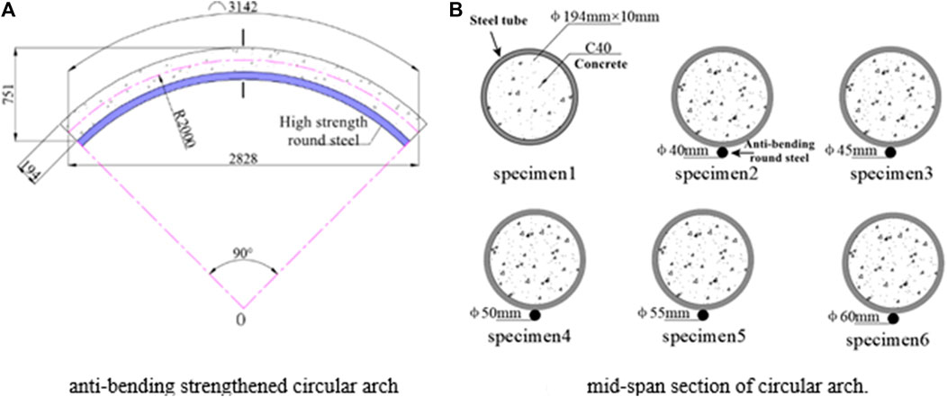
FIGURE 2. Size diagram and section feature diagram of circular arch structure strengthened by anti-bending.
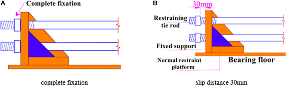
FIGURE 3. Design of slip quantity of support.
The structural laboratory of the School of Civil Engineering at Shandong Jianzhu University is where the test was conducted using a big reaction frame test bench. As seen in Figure 4A, B, the 200t hydraulic jack (both sides) and 500t hydraulic jack (vault) were employed. The three jacks are operated by the same hydraulic control system to produce synchronous equal pressure output for the loading form, which then allows for the realization of top centralized loading (vault 3 point loading) and full span uniform loading (full span 11 point loading) via the primary and secondary distribution beams. At the same time, the paired support plates are employed to create lateral restraints to prevent the circular arch from becoming out-of-plane.
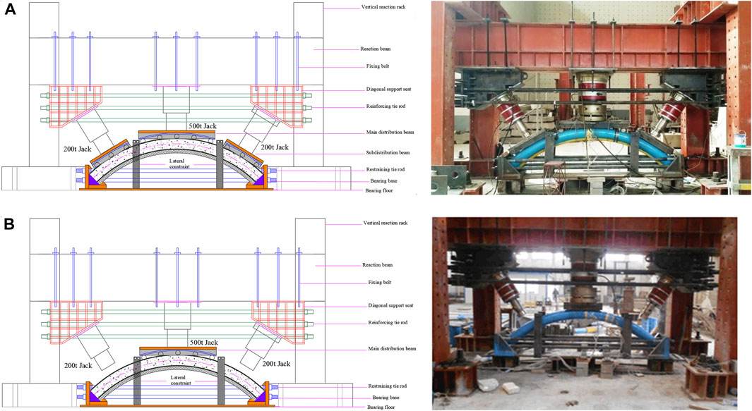
FIGURE 4. Design structure and picture of test bench.
The effect of support slip and anti-bending strengthening on the bearing performance of a circular arc arch was investigated, and the compression-bending deformation mechanism of a circular arc arch, which mostly contains neutral layer migration and anti-bending strengthening law, was developed.
(1) Test results under the constraint of full-span uniform distribution point loading + fixation
The CFST circular arch was tested, with the arch web welded with 45 mm bending round steel. There was no slide in the arch foot, and the full-span typical uniform point load was applied. When the jack load is 2000 kN, the vertical displacement of the specimen is approximately 10 mm; when the load is 3,000 kN, the vertical displacement of the specimen is approximately 18 mm. Continue to load until the hydraulic system’s pressure reaches the limit, at which point the test is terminated. The vertical residual distortion in the middle span after unloading is 8 mm, and the deformation is nearly imperceptible.
(2) Test results under concentrated loading + fixed constraints on vault
There is no slide at the arch foot and concentrated loading at the arch top in the case of the circular CFST arch that was welded with 45 mm bending round steel on the soffit. Test methodology: When the vault jack force reaches 2000 kN, the specimen’s mid-span displacement is 15 mm; when the jack load is increased to 3000 kN, the specimen’s mid-span displacement is 30 mm, but the structural deformation is still not immediately apparent. The hydraulic system is now overrun once more, and the test is terminated. The specimen is somewhat distorted after unloading with a 20 mm vertical residual distortion.
(3) Test results of arch crown concentrated loading + arch foot sliding
As shown in Figure 5A, the CFST circular arch with 45 mm bending round steel is chosen to carry out concentrated loading on the vault because the results of the previous two tests are not statistically significant. Additionally, the slip of the arch foot is reserved on both sides of the support for 30 mm.
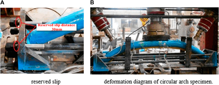
FIGURE 5. Test results of circular arch under top concentrated loading + arch foot slide.
The supports at both ends progressively slide during the first loading stage, and the displacement in the middle of the span steadily grows. When the support’s slip is complete, the strain on the arch jack is 600 kN, and the specimen’s mid-span displacement is around 60 mm—almost equal to the total of the slip amounts of the two arch feet. The top of the arc arch plainly lowers and tends to be straight when the jack is loaded to 1950 kN. The specimen deforms visibly and displays waist drum deformation features on both sides of the mid-span when the jack is loaded to 2,390 kN (114 mm of mid-span displacement). In Figure 5B, the specimen’s total deformation is depicted. Other arc arch research made use of the same experimental setup. As shown in Figure 6, relationship curves between the top load and the circular arch’s mid-span displacement are created based on three testing conditions. When the support is fixed, the circular arch works well regardless of whether the load is uniformly distributed throughout the whole span or concentrated in the vault. When the support has arch foot slip, the carrying capacity of a circular arch increases gradually and linearly, which is compatible with the characteristics of a curved beam (Wang, 2014). After the support slips, the circular arch receives a horizontal push from the fixed end support, the curved beam effect is diminished, the circular arch’s axial compression effect is intensified, and the circular arch’s bearing capacity grows quickly until the component is destroyed.
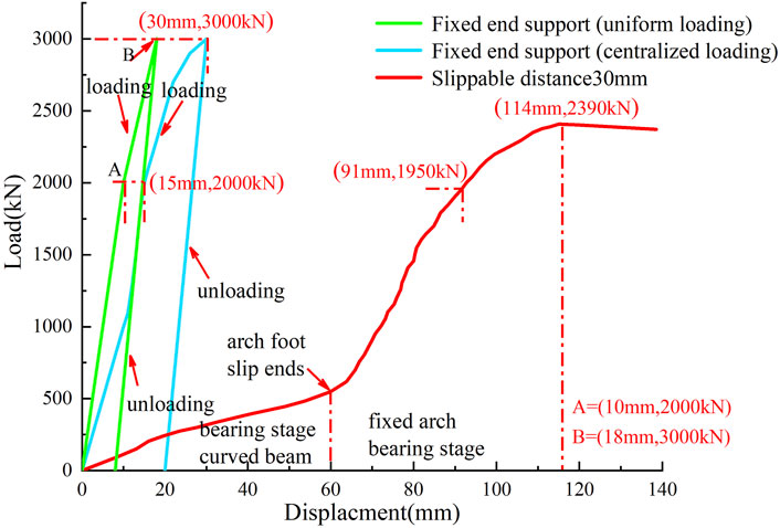
FIGURE 6. Relation curve between top load and mid-span displacement of circular arch.
As illustrated in Figure 7, the relationship curve between vault load and mid-span displacement is drawn after the test results of the bending-reinforced circular arch are combined. The diagram shows that by welding the anti-bending round steel to the arch belly, the circular arch’s ultimate bearing capacity is significantly increased due to the increased tensile strength of the arch belly. Early on in the arch force, the difference gradually becomes noticeable, and by the time the arch foot slip has ended, it is extremely clear. Last but not least, the CFST circular arch with anti-bending round steel outperforms the circular arch without anti-bending round steel significantly in terms of bearing capacity, improving the ultimate bearing capacity by 430 kN and lowering the mid-span displacement by 37 mm. The diameter of the anti-bending round steel is closely associated with the bearing capacity of the circular arch. The ultimate bearing capacity of a circular arch increases with the diameter of the round steel under the same load, while the mid-span displacement decreases as the anti-bending strengthening increases. However, the anti-bending strengthening power rapidly declines as the diameter of the round steel grows.
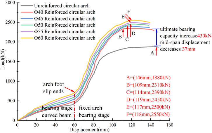
FIGURE 7. Load-displacement curves of circular arch strengthened by anti-bending.
It is discovered that the deformation of the six circular arch specimens is essentially the same under concentrated load: the vault flattens and the entire structure becomes a “flat bow,” as seen in Figure 8. When the steel tube in the mid-span straight section of the arc arch without anti-bending reinforcement was opened, it was discovered that the concrete in the soffit section was clearly cracked, with the cracks primarily concentrated in the straight section of the arch and developing from the tension side to the compression side. After cutting the steel tube of the anti-bending reinforced circular arch, it was discovered that the concrete’s cracking mechanism is comparable. However, when the diameter of the anti-bending round steel increases, the fracture range and depth steadily diminish, demonstrating that the anti-bending round steel successfully resists concrete cracking by bearing a significant amount of tensile force and reducing the load applied to the concrete. The concrete at the waist drum of the unreinforced circular arch is crushed without developing cracks, which is compressive failure. Additionally, there is a wavy waist drum deformation from the arch shoulder to the inner arc side of the arch foot.
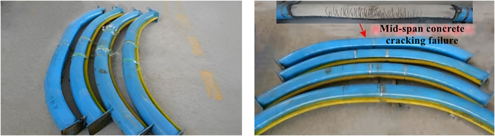
FIGURE 8. Concrete filled steel tubular circular arch compression and bending deformation diagram.
On the circular arch’s mid-span portion, strain gauges have been glued. To track the variations in strain in the mid-span portion, a total of 28–30 strain gauges are glued at equal angles. The neutral layer was the surface on which the zero line of strain value was found. The mid-span displacement and the neutral layer offset relationship curve are produced using the horizontal plane, where the center of the steel tube is positioned as the zero point. According to Figure 9, the neutral layer of the circular arch rises higher during the arch foot slip stage, suggesting that the area of the tension zone of the section expands and the compression zone contracts. The circular arch creates the appearance of a curved beam, and the arch’s bending moment is large. When the arch foot no longer slipped, the neutral layer of the circular arch migrated lower, the area of the section compression zone expanded, the tension zone dropped, and the arc arch progressively manifested an axial compression effect while also strengthening its axial force effect.
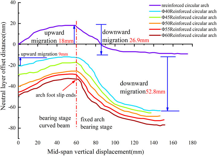
FIGURE 9. Mid-span displacement-neutral layer offset distance curves of circular arch.
The neutral layer of the unbendingly strengthened circular arch is first positioned in the middle of the steel tube section, whereas the neutral layer of the antibendingly strengthened circular arch is initially positioned lower. The starting location of the neutral layer is lower the greater the diameter of the anti-bending round steel is on the ventral side of the circular arch. The tension zone of the circular arch is always smaller than the compression zone, which significantly increases the circular arch’s anti-bending resistance. All of the anti-bending, strengthened circular arch neutral layers are always located below the center of the steel tube section. The offset value of the neutral layer decreases by 52.8 mm at the ultimate bearing point of the circular arch and by 26.9 mm at the end of the arch foot slip as the diameter of the bending round steel increases from 0 to 40 mm, which is similar to the proportional antisymmetry of the increase in ultimate bearing capacity.
In order to find an appropriate method of CFST support optimization, other factors affecting the bearing capacity of circular arches should also be thoroughly studied during the test. Numerical simulation is used to supplement the analysis. The test primarily examines the influence of arch foot slip and anti-bending strengthening.
Based on the test results, ABAQUS finite element software was used to model and analyze, and the orthogonal test analysis was carried out through numerical simulation to further study the compression-bending load-bearing characteristics of the CFST circular arch under the influence of other factors. The influence of various factors on the load-bearing performance of the circular arch was determined.
The effect parameters of the circular arch were preliminary optimized based on references (Wang. 2014) and typical support types in deep highway support, and a multi-factor orthogonal test table was created. As indicated in Supplementary Table S2, certain sample sites from the comprehensive test are chosen in accordance with the orthogonality to conduct the test, and the full-span normal uniform load and the vault focused load are applied accordingly. According to the actual stress area of the concrete-filled steel tube support in the surrounding rock, the actual stress state of the surrounding rock is realized through the pressure in the Load module of ABAQUS. In order to prevent out-of-plane instability, the arch foot adopts fixed limitations, and the entire construction cannot be offset. By specifying tangential friction and radial compression contact-adhesive sliding friction, the interaction between the steel tube and the core concrete contact surface is simulated.
For the steel tube, the isotropic elastic-plastic model (Xie et al., 2015) is used, which complies with the relevant flow criteria and the Von Mises yield criterion. The concrete constitutive parameters are displayed in Supplementary Table S3 for the C40 core concrete, which is constructed using a Concrete Damaged Plasticity model that is subject to the non-correlated flow criteria.
The Analyzed is the circular arch model made of CFST measuring 194 mm by 10 mm without anti-bending strengthening. The circular arch fails in flat bow failure mode when there is concentrated weight on the vault and no arch foot slip, and waist drum failure mode manifests on both sides of the vault. The ‘waist drum’ characteristic on both sides of the vault eventually disappears as the arch foot slips more, and as illustrated in Figure 10, the stress concentration and ‘waist drum’ phenomena occur there instead. Under the condition of full-span normal uniform loading, with the increase of slip, the failure mode of circular arch gradually evolves from vault protrusion to ‘M' shape, and the arch foot also appears stress concentration and ' waist drum ' phenomenon, as shown in Figure 11.
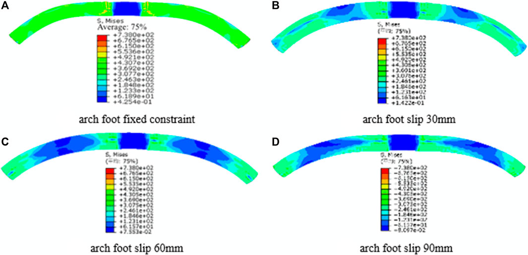
FIGURE 10. Stress nephogram of concrete-filled steel tube circular arch with different arch foot slip (concentrated load on vault).
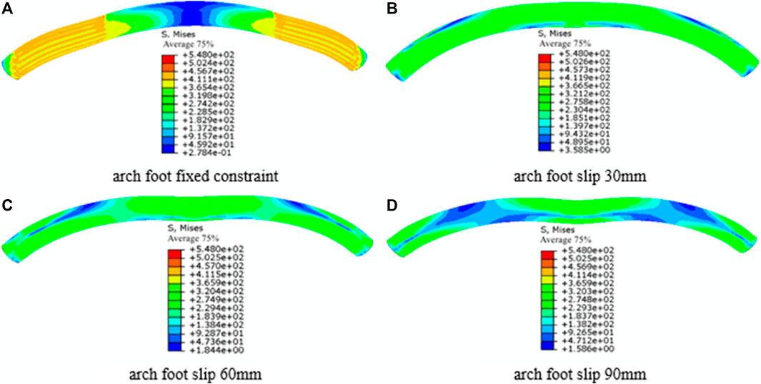
FIGURE 11. Stress nephogram of concrete filled steel tube circular arch with different arch foot slip (full span normal uniform load).
The mid-span load and mid-span displacement correlation curves are depicted. As shown in Figure 12A, the ultimate bearing capacity of the CFST circular arch is lowered by 40.8% cliff-like under the situation of concentrated stress on the vault when the fixed constraint of the arch foot is changed to the arch foot slip of 30 mm. The final bearing capacity is decreased by 25.9% and 48.1%, respectively, as the arch foot slip rises from 30 mm to 60 mm and 90 mm. The carrying capacity of the circular arch with a slip of 90 mm is reduced by 88.9% when compared to the circular arch with fixed limitations at the arch foot.
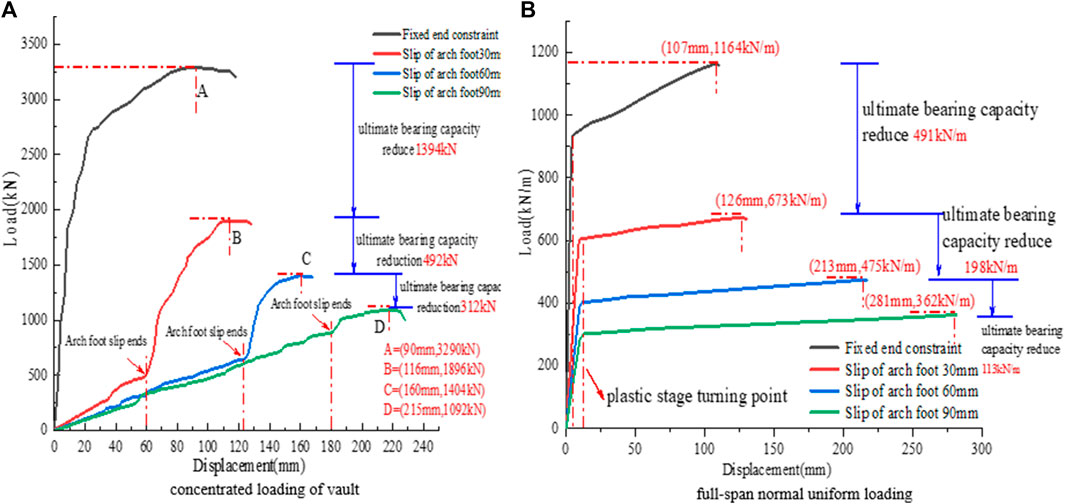
FIGURE 12. Mid-span load-displacement curves of concrete filled steel tube circular arch with different arch foot slip.
As can be observed from Figure 12B, when the arch foot slips, there is no correlation between the vertical displacement of the mid-span and the arch foot slip under the condition of full-span normal uniform loading. The ultimate carrying capacity of the CFST circular arch is lowered by 35% in a cliff-like manner when the fixed restriction of the arch foot is adjusted to 30 mm. The ultimate bearing capacity decreases by 29.4%, 53.2%, and 88.2%, respectively, when the arch foot slip is raised from 30 mm to 60 mm and 90 mm, respectively. The bearing capacity of the circular arch with 90 mm of slip decreases by 88.2%. The circular arch’s stability and safety are thus greatly endangered by the arch’s foot slip.
The research mentioned above demonstrates that when the slip of the arch foot increases, the bearing capacity of the circular arch quickly diminishes. When the arch foot slip reaches 90 mm under focused loads, the circular arch even loses its noticeable arch effect after the slip has ended, degrading immediately into a curved beam, and the structural benefits of CFST all but vanish. As the arch foot slip grows under the full-span normal uniform load, the plastic deformation section progressively rotates clockwise, suggesting that the plastic strengthening capacity gradually declines as a result of the arch foot slip.
The stress nephograph of the circular arch is extracted after simulating the arch with various outer diameters, a wall thickness of 10 mm, and no slide at the arch foot. This is depicted in Figure 13: Stress concentration occurs on both sides of the vault and arch foot under concentrated loading on the vault, and the more apparent the waist drum phenomenon on both sides of the vault, the more likely the “flat bow” failure mode of the specimen as a whole. The specimen was convex overall under the full-span uniform normal load, and the “waist drum” characteristic appeared close to the arch foot. The more pronounced the “waist drum” feature, the larger the outside diameter.
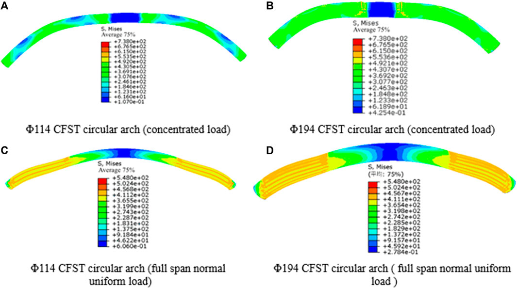
FIGURE 13. Stress nephogram of concrete filled steel tube circular arch with different outer diameters.
It is concluded that there is a correlation between mid-span load and mid-span displacement. According to Figure 14A, when the outer diameter of the steel tube filled with concrete is increased from 114 mm to 140, 168, and 194 mm progressively under concentrated loading of the vault, the cross-sectional area increases by 50.8%, 44.0%, and 33.3%. The CFST circular arch now has an enhanced ultimate bearing capacity of 53.6%, 50.2%, and 29.6%, respectively. The contribution degree of the new section is measured as the ratio between the growth rates of bearing capacity and CFST cross-sectional area, and the values are 1.05, 1.14, and 0.887, respectively. This ratio illustrates a trend of initially increasing and then dropping.
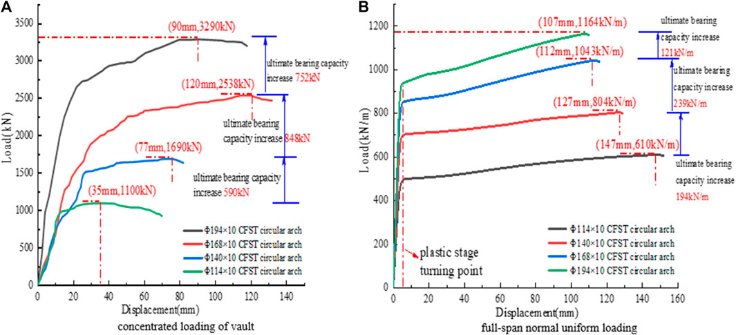
FIGURE 14. Mid-span load - displacement curves of concrete filled steel tube circular arch with different outer diameters.
The ultimate bearing capacity of CFST circular arches increases by 31.8%, 29.7%, and 11.6%, respectively, as the outer diameter is gradually raised from 114 mm to 194 mm under full-span normal uniform loads, as shown in Figure 14B. The contributions of the new section are 0.626, 0.675, and 0.348, respectively, which also exhibit a tendency of increase followed by decline, but the increase is modest and the decline is substantial.
The stress nephograph of circular arches is retrieved by performing numerical simulations on circular arches with various wall thicknesses, an outer diameter of 194 mm, and a non-slip arch foot. The circular arch’s failure mode and stress concentration phenomenon are consistent with the explanation in Section 4.2.2, which is no longer repeated, as illustrated in Figure 15.
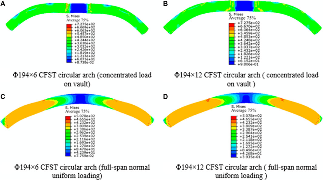
FIGURE 15. Stress nephogram of concrete filled steel tube circular arch with different wall thickness.
According to Figure 16A, when the wall thickness of the steel tube is gradually increased from 6 to 12 mm, the cross-sectional area of the pure steel tube increases by 31.9%, 23.6%, and 18.7%, respectively, and the ultimate bearing capacity of the CFST circular arch increases by 20.3%, 21%, and 13.2%, respectively. This is because the correlation curve is drawn using the mid-span load and the mid-span displacement. The contribution of new steel tubes is measured as the ratio of the growth rate of bearing capacity to the growth rate of steel tube area. The contribution rates, which show a tendency to grow initially and then fall, are 0.636, 0.887, and 0.706, respectively.
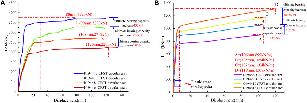
FIGURE 16. Mid-span load-displacement curves of concrete filled steel tube circular arch with different wall thicknesses.
Figure 16B illustrates how, under the influence of full-span normal uniform loads, the ultimate bearing capacity of a CFST circular arch improves by 17.2%, 10.4%, and 12.3%, respectively, as the wall thickness of steel tube increases from 6mm to 12 mm. The relative contribution rates were 0.539, 0.440, and 0.658, with a pattern of first falling and then increasing.
In conjunction with the study in Section 4.2.2, the growth rate of the CFST circular arch’s bearing capacity gradually slows down as the outer diameter and wall thickness of the steel tube rise. In addition, there should be an ideal contribution for the concentrated loading condition of the vault, meaning that the outer diameter should be between 114 and 194 mm, or roughly 168 mm, and the wall thickness should be between 6 and 12 mm, or roughly 10 mm. However, the ideal combination of wall thickness and outer diameter has not been discovered under the full-span normal uniform stress situation.
With no slip at the arch foot and no anti-bending strengthening, a simulation study of various rise-span ratios of 194 mm 10 mm CFST circular arches is conducted. As seen in Figure 17, the stress nephogram is extracted. The overall failure mechanism of the vault under concentrated loading conditions is “flat bow,” and there is a clear “waist drum” occurrence on both sides of the vault. According to Figure 18, when full-span normal uniform loading is applied, the specimen’s vault is slightly convex, the arch foot is positioned in a way that resembles a “waist drum” and the stress concentration occurs on the arch foot’s bottom side.
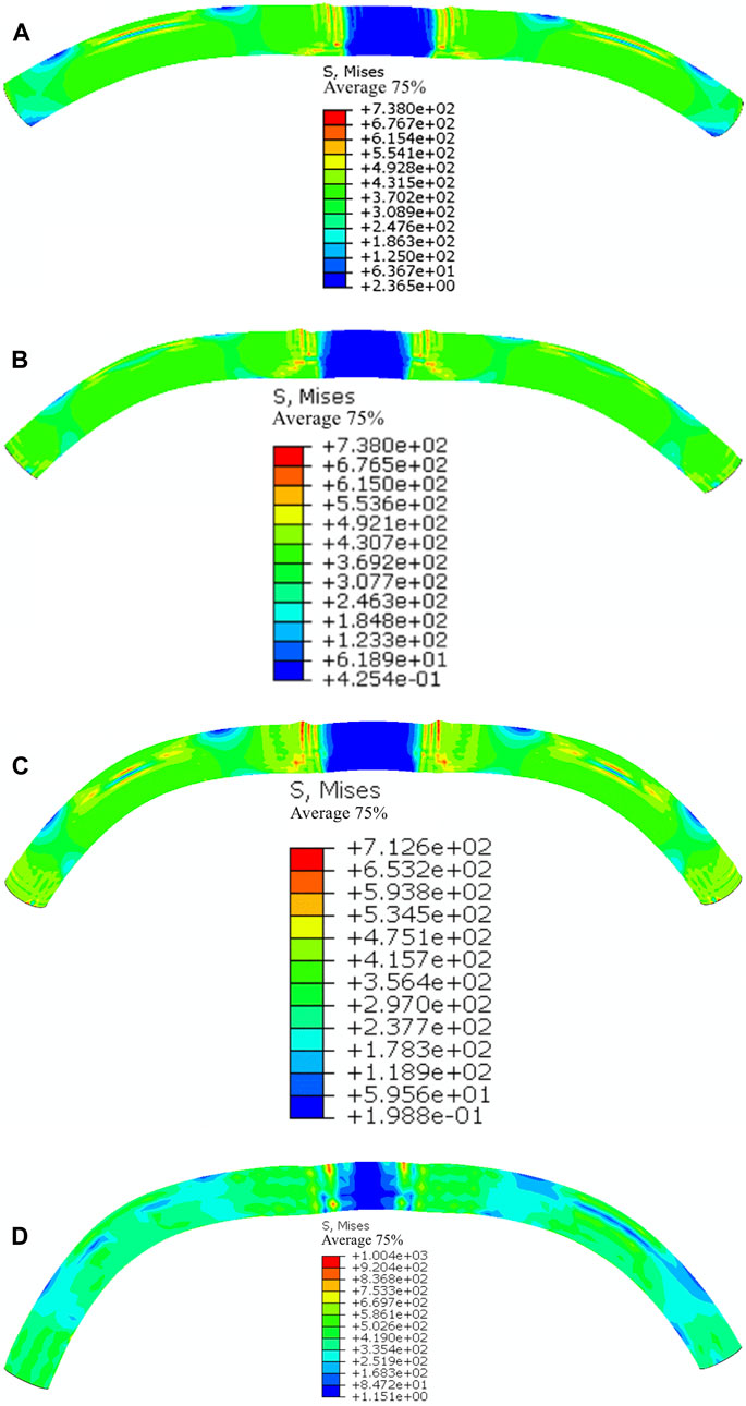
FIGURE 17. Different rise-span ratio of concrete filled steel tube circular arch stress nephogram (concentrated load on vault).
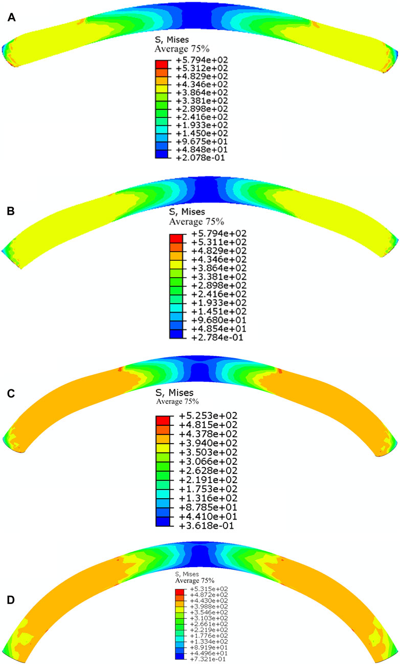
FIGURE 18. Different rise-span ratios of concrete filled steel tube circular arch stress nephogram (full span normal uniform load).
By adding the mid-span load and the mid-span displacement, the correlation curve is created. As observed in Figure 19A, the rise-span ratio increasing from 0.154 to 0.30 enhances the ultimate bearing capacity of CFST circular arches by 21.2%, 7%, and 2%, respectively, under the situation of concentrated load on the vault. As observed in Figure 19B, the ultimate bearing capacity of the CFST circular arch improves by 35%, 9.9%, and 4.99%, respectively, when the rise-span ratio rises from 0.154 to 0.260 under the condition of a full-span uniform load. The contribution of the new rise-span ratio is measured as the ratio of the growth rate of ultimate bearing capacity to the growth rate of the rise-span ratio. The contributions are 0.616, 0.273, and 0.11 in the scenario of focused loading on the vault, respectively. The contributions under the full-span normal uniform load are 1.017, 0.387, and 0.201, respectively. As the rise-span ratio rises, it is evident that the contribution falls.
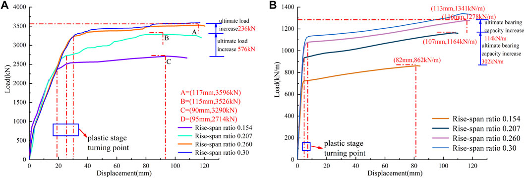
FIGURE 19. Mid-span load -displacement curves of circular concrete filled steel tube circular arch with different rise-span ratios.
The orthogonal test is designed, computed, and sorted out by Design-Expert software as indicated in Supplementary Table S4 and the aforementioned simulation results are sorted out. It is evident that as tube diameter, wall thickness, and rise-span ratio increase, so does the circular arch’s bearing capability. The circular arch’s bearing capacity declines as arch foot slip increases, and the arch effect progressively disappears.
According to statistical analysis, the slip of the arch foot is the most important component impacting the bearing performance of the circular arch of CFST under centralized arch loading or full-span normal uniform loading. The carrying capacity of a circular arch gradually declines and weakens into a curved beam as arch foot slip increases. The bearing capacity of a circular arch improves as steel tube diameter, wall thickness, rise-span ratio, and anti-bending strengthening increase. However, the rise-span ratio has a bigger impact than anti-bending strengthening when the outer diameter and wall thickness of a steel tube are the same. Under the same rise-span ratio, the influence of the steel tube’s outside diameter is marginally stronger than its wall thickness and stronger than its anti-bending strengthening. The outside diameter of the steel tube is 168 mm, the wall thickness is 10 mm, the rise-span ratio is 0.207, and the ultimate failure mechanism is local waist drum deformation failure. These specifications provide the circular arch’s bearing capacity under concentrated loads.
When there is no arch foot slip, the mid-span load and mid-span displacement curves of circular arches in supine are essentially the same. The circular arch failure is essentially the deformation and failure of the arch foot or spandle brought on by axial compression exceeding the limit, meaning that the CFST structure locally experiences the ultimate compression failure. The compression-bending failure mode of the circular arch and the load shape have weak correlations when there is an arch foot slide. It is mostly impacted by the arch of the foot sliding, and noticeable buckling deformation features gradually arise. As a result, the CFST’s bending moment exceeds the limit, which is consistent with the results of the orthogonal test.
When the arch foot slip reaches a particular point, the circular arch loses its arch effect forever. Therefore, it is impossible to avoid using the planned deformation space or construction gap between the support and the surrounding rock in the actual support. The displacement of the support from the filling space caused by an uncompacted filling is analogous to the circular arch experiment’s arch foot slip. The void behind the support wall or the excessive pressure space, as well as the construction gap, must be avoided in order to guarantee that the arch axial compression effect of the circular CFST support is considerable.
The integrated support of the roadway is created once many circular supports have been built, as shown in Supplementary Figure S1. The circular CFST support is made up of four circular arches. Studying the use of circular CFST supports in the Yangcheng Coal Mine’s North Third Deep Track, operated by Jining Mining Group.
The Yangcheng Coal Mine of the Jining Mining Group has several rock faults, a deep mining depth, and complex geological circumstances. The average downhill buried depth of the third deep track is close to 1000 m. Medium sandstone, siltstone, and mudstone make up the roadway’s excavation layer. Because of the surrounding rock’s high vertical stress, poor strength, and severely inadequate self-bearing capability, the side wall of the road may flex significantly, and there may be significant floor heave. The surrounding rock is in a high ground stress state before the opening of the roadway, and the tectonic stress field is complex. These are the features of the stress field of the roadway in the ultra-deep well. After the opening of the roadway, high concentrated stress and deviatoric stress appear in the surrounding rock, which results in a significant change in the surrounding rock’s deformation characteristics: the deformation of the surrounding rock shifts from brittleness to plasticity, and the rheology and dilatancy of the surrounding rock are prominent. The mine repeatedly tried to stabilize the roadway by using support techniques like “full-section hollow grouting anchor cable + bolt + floor pouring C40 concrete” and “anchor net spray + U29 steel,” but these efforts were unsuccessful. With the analysis of the deep support mechanics principle combined (Kong et al., 2015; Xie et al., 2015), the deep track downhill support adopts the composite support scheme of “anchor net spray + circular CFST support,” the roadway section is optimized to be circular, and the reserved space between the support and surrounding rock is filled with gangue bags. Supplementary Figure S2 displays the support layout.
The modeling and analysis were done using ABAQUS finite element software to confirm the viability of circular CFST support. The references (Shan et al., 2015; Xie et al., 2015) and the surrounding rock geology of the track downhill confirm the preliminary estimate of 1.15–1.45 MPa for the surrounding rock load acting on the support. A 3.0 MPa uniform load is applied to the support model in order to intuitively examine the support’s performance. In Supplementary Figure S3, the simulation results are displayed. The support has a strong overall bearing performance. The track downhill highway at Yangcheng Coal Mine can be made safe and stable by having a maximum side displacement of about 7 mm and a maximum vault displacement of about 4 mm.
The downward slope of the Beisan deep track has maintained long-term stability since the support plan was established in 2020. Real-scene images of the on-site support obtained at the end of 2022 show that the roof, floor, and two sides are all well regulated, with just 1%–2% of the support deforming (Supplementary Figure S4A). Under this support scheme, the roof and the upper part get a good control effect, and they are basically stable after 25d. The displacement change curve is shown in Figure 13. The roof displacement is 109 mm, the roof subsidence is small, the maximum subsidence is 50 mm, and the maximum floor heave is about 70 mm. As shown in Supplementary Figure S4B.
The two primary kinds of CFST support deformation are the support’s overall buckling deformation failure and the failure of the support’s waist drum.
1. The overall buckling deformation failure and optimization analysis of the support
The top arc section or side section of the CFST support typically exhibits this type of damage, and as can be seen in Supplementary Figure S5, there is a clear distinction between the upper and bottom portions of the joint casing. These are the primary causes: 1) Installation clearance room (about 10 mm) is often reserved in the joint casing (e.g., Φ223 mm × 10 mm) to guarantee the primary steel tube of the support (e.g., Φ194 mm × 10 mm) is installed without difficulty. As a result, after applying restricting pressure at the joints of each segment (i.e., the arch foot), the support will slide and the CFST at the joints will progressively split, as illustrated in Supplementary Figure S6. 2) It is difficult to place gangue bags above the shoulder joint sleeve in engineering, and the filling behind the wall is frequently not dense. Gangue bags are filled behind the support wall below the shoulder joint sleeve. The joint casing will be shifted or deflected as the support is squeezed, which is analogous to “arch foot slip” and reduces the arch effect while improving the curved beam effect. The circular arch is vulnerable to yielding under bending moments.
Therefore, the arch effect of the support should be increased and the anti-flexural bearing capacity should be improved in order to assure the stability of the concrete-filled steel tube support. You can utilize the three optimization techniques listed below: 1) To stop the end face of the main steel tube from separating, reduce the slip in the joint casing, raise the limit steel bar in the casing, and create reinforced concrete at the junction after pouring concrete; 2) Develop filling equipment, lower labor intensity, and ensure filling quality; 3) Weld the anti-bending round steel on the inside and outside of the circular arch to increase the support’s bearing capacity for resistance to bending. This is done by optimizing the backfill of the support wall and filling the backfill of the full broken face with tightness.
2. Deformation failure and deformation analysis of support waist drum
The distortion of the CFST waist drum, as seen in Supplementary Figure S7, is the primary manifestation of this type of deformation and failure, which mostly manifests in the upper and lower regions of the joint casing or the side section. The general form of the support is currently steady and does not alter appreciably. The steel tube at the waist drum will crack and further break as the pressure from the surrounding rock increases, as shown in Figure 20, but it can still transmit axial pressure at this point, though the anti-bending resistance is almost completely lost. The primary cause is that the side wall portion of the support, which carries the weight of the roof and floor and has a tendency to bend when subjected to the surrounding rock, cannot be deformed by passive restraint from the rock, and there is high axial pressure in the arc arch. The axial compression effect gradually gets stronger, and the waist drum deforms under the impact of adjacent mining disturbances or the buildup of surrounding rock pressure. Steel tube breaking will result from increased waist drum deformation, which is brought on by the circular arch’s axial compression’s insufficient bearing capacity.
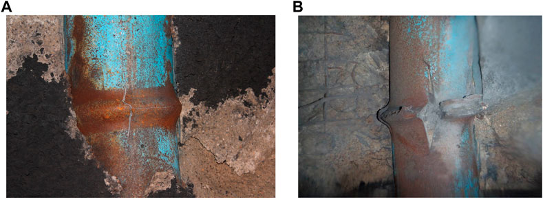
FIGURE 20. Circular concrete-filled steel tube support.
As a result, the absence of axial compression bearing capacity is the primary cause of waist drum deformation. However, at this point, the concrete-filled steel tube support has achieved its maximum bearing capacity, which makes it an optimal mode of failure. On the basis of addressing the filling behind the support wall, the support’s ability to withstand axial compression should be increased. There are three types of optimization: 1) raise the steel tube’s outer diameter, wall thickness, or concrete’s strength and enhance the circular arch’s axial compression bearing capacity, particularly the side portion of the support; 2) Under mining disturbance conditions, pressure relief behind the support wall should be performed on time to properly buffer the surrounding rock load of the circular arch of the side section; 3) Adopt high-strength active support technology or surrounding rock grouting modification technology to differentiate the surrounding rock load acting on the CFST support and achieve composite support stability.
The following results are established from the bearing test, numerical simulation, and engineering application study of the CFST circular arch:
1. In spite of centralized loading or full-span normal uniform loading, the circular arch of the CFST demonstrates greater bearing capacity when constrained by fixed arch feet. Under the situation of a full-span normal uniform load, the bearing capacity of a circular arc arch is superior to that of a concentrated load. The impact of the CFST’s circular arch curved beam is improved, the neutral layer is transmitted to the compression zone, and the arch’s bearing capacity gradually rises throughout the arch foot slip process. After the arch foot slips, the circular arch effect is reestablished, and the bearing capacity quickly increases. However, the circular arch immediately degrades into a curved beam without an arch effect when the slip of the arch foot exceeds 90 mm. When there is a concentrated load, the circular arch span’s vertical displacement is approximately equal to the total slip of the two arch feet.
2. The numerical simulation research demonstrates that, for steel tubes with the same outer diameter and wall thickness, the impact of the rise-span ratio is larger than that of anti-bending strengthening. The impact of the steel tube’s outer diameter is slightly greater than that of its wall thickness under the same rise-span ratio. The circular arch is defined by the distortion of the arch side or the vault’s “waist drum” when there is no or only a slight slip at the arch foot. The circular arch exhibits general buckling deformation failure characteristics when the arch foot has a significant slip or the rise-span ratio is too short; The optimal bearing performance parameters for a circular arch with an outside diameter of 168 mm, a wall thickness of 10, and a rise-span ratio of 0.207 are found under concentrated load, and local waist drum deformation is the failure mode.
3. The composite support scheme of “anchor net spraying + CFST support” is suggested for the real project, and it essentially resolves the support issue. Analysis was done on the support’s waist drum deformation and buckling deformation. It should be fair to minimize the installation clearance space of the joint casing or to reinforce the support wall since the buckling deformation of the support was brought on by insufficient anti-flexural capability. The CFST support’s inadequate axial compressive capability is shown by the waist drum’s deformation. The ultimate bearing condition of the material is reached at this point in the deformation. Improvements should be made to the steel tube’s outer diameter, wall thickness, or concrete strength, and the side pressure relief should be completed promptly.
The investigation for this project is ongoing and does not just focus on the mechanical characteristics of the passive support system. Further optimization of the control strategy and rock factors surrounding the road is required. It is vital to thoroughly examine the influencing variables of surrounding rock deformation and identify the deeper control mechanism in order to address the issue of surrounding rock deformation and failure in soft rock, high-stress roadways, or junctions in a kilometer-deep well. The next stage is to research the CFST support (passive support + active support + grouting modification + backfill pressure relief) combined support technique for surrounding rock control in order to achieve space-time synergy.
The original contributions presented in the study are included in the article/Supplementary Material, further inquiries can be directed to the corresponding author.
WJ: Funding acquisition, Investigation, Supervision, Writing–original draft, Writing–review and editing. ZC: Formal Analysis, Software, Writing–original draft, Writing–review and editing. BF: Investigation, Project administration, Writing–original draft. XG: Investigation, Writing–original draft. LY: Investigation, Writing–original draft. WB: Funding acquisition, Writing–original draft. DG: Investigation, Writing–original draft. TZ: Investigation, Writing–original draft.
The author(s) declare financial support was received for the research, authorship, and/or publication of this article. This work is Supported by the National Natural Science Foundation of China (Grant No. (52274121), the National Natural Science Foundation of Shandong Province (Grant No. (ZR2022ME162), the National Natural Science Foundation of Hebei Province (Grant No. (E2022508023) and Research leader Studio of “20 New Universities” funded project in Jinan City (Grant No. (202228106).
Authors BF, XG, LY, DG, and TZ were employed by Shandong Jikuang Luneng Coal Power Co Ltd.Yangcheng Coal Mine.
The remaining authors declare that the research was conducted in the absence of any commercial or financial relationships that could be construed as a potential conflict of interest.
All claims expressed in this article are solely those of the authors and do not necessarily represent those of their affiliated organizations, or those of the publisher, the editors and the reviewers. Any product that may be evaluated in this article, or claim that may be made by its manufacturer, is not guaranteed or endorsed by the publisher.
The Supplementary Material for this article can be found online at: https://www.frontiersin.org/articles/10.3389/fmats.2023.1285551/full#supplementary-material
Bradford, M. A., Pi, Y.-L., and Qu, W. (2011). Time-dependent in-plane behaviour and buckling of concrete-filled steel tubular arches. Eng. Struct. 33 (5), 1781–1795. doi:10.1016/j.engstruct.2011.02.018
Gao, Z., and Yan, F. (2020). Probability theory and mathematical statistics. Nanjing, China: Nanjing University Pres.
Gao, Y., Wang, Bo, Wang, J., et al. (2010). Test on structural property and application of concrete - filled steel tube support of deep mine and soft rock roadway. Chin. J. Rock Mech. Eng. 29 (S1), 2604–2609. (in Chinese).
Han, Xu, Fernando, D., and Han, B. (2020). Numerical modelling of the in-plane behaviour of concrete-filled circular steel tubular arches. Constr. Build. Mater., 264. doi:10.1016/j.conbuildmat.2020.120693
He, X., Liu, K., Zhang, L., et al. (2015). Structuraldesign and application of concrete-filled steel tube support at extremely soft rock roadway intersection. J. China Coal Soc. 40 (9), 2040–2048. (in Chinese). doi:10.13225/j.cnki.jccs.2014.1704
Hu, Q., Chang, Y., Yuan, C., Wang, Y., and Zhang, S. (2018). Experimental investigation into in-plane stability of concrete-filled steel tubular parabolic arches under five-point concentrated loads. Int. J. Steel Struct. 20, 2038–2050. doi:10.1007/s13296-020-00429-y
Kang, H., Fan, M., Gao, F., et al. (2015). Deformation and support of rock roadway at depth more than 1000 meters. Chin. J. Rock Mech. Eng. 34 (11), 2227–2241. (in Chinese). doi:10.13722/j.cnki.jrme.2015.0859
Li, S., Wang, Qi, Jiang, B., He, M., Sun, H., Shao, X., et al. (2017). Modeling and Experimental study of mechanical properties of confined concrete arch in complicated deep underground engineering. Int. J. Geomechanics 17 (6), 1–14. doi:10.1061/(asce)gm.1943-5622.0000827
Li, X., Yang, R., Gao, Y., et al. (2013). High-strength steel tubular confined concrete supports support technology for large section soft rock inclinedshaft. J. China Coal Soc. 38 (10), 1742–1748. (in Chinese). doi:10.13225/j.cnki.jccs.2013.10.018
Liu, D., Zuo, J., Guo, S., et al. (2018). Research on load-bearing ability of steel tube confined concrete sup-ports for deep roadway: state of the art. J. China Univ. Min. Technol. 47 (6), 1193–1211. doi:10.13247/j.cnki.jcumt.000942
Lu, W., and Sun, H. (2020). Study on support characteristic curve of concrete-filled steel tubular arch in underground support. Structures 27, 1809–1819. doi:10.1016/j.istruc.2020.07.066
Luo, K., Pi, Y.-L., Gao, W., Bradford, M. A., and Hui, D. (2015). Investigation into long-term behaviour and stability of concrete-filled steel tubular arches. J. Constr. Steel Res. 104, 127–136. doi:10.1016/j.jcsr.2014.10.014
Pi, Y.-L., Bradford, M. A., and Qu, W. (2011). Long-term non-linear behaviour and buckling of shallow concrete-filled steel tubular arches. Int. J. Non-Linear Mech. 46 (9), 1155–1166. doi:10.1016/j.ijnonlinmec.2011.05.003
Shan, R., Xiao, Y., Liu, K., et al. (2018). Failure mechanism of the arch of concrete filled steel tube supports component. J. China Coal Soc. 43 (07), 1918–1929. (in Chinese). doi:10.13225/j.cnki.jccs.2018.0004
Wang, J. (2014). Research on mechanical properties of anti-bending for Concrete filled Steel circular arch and its application. Ph.D. Thesis. Beijing, China: China University of Mining and Technology Beijing. (in Chinese).
Wang, Qi, Xu, S., Jiang, B., et al. (2020). Research progress of confined concrete support theory and technology for underground engineering. J. China Coal Soc. 45 (8), 2760–2776. doi:10.1016/j.enpol.2013.02.011
Wang, Y., Liu, C., Yonglin, P. I., et al. (2011a). In-plane nonlinearity stability strength of circular concrete-filled steel tubular arches. J. Huazhong Univ. Sci. Technol. Sci. Ed. 39 (05), 34–38. (in Chinese). doi:10.13245/j.hust.2011.05.027
Wang, Y., Wu, X., Geng, Y., et al. (2011b). Analysis on creep stability of concrete-filled steel tubular arches under uniform load. Prog. Steel Build. Struct. 13 (06), 31–35+43. (in Chinese)). doi:10.13225/j.cnki.jccs.2019.0920
Xie, H., Gao, F., Yang, J. U., et al. (2015). Quantitative definition and investigation of deep mining. J. China Coal Soc. 40 (1), 1–10. (in Chinese). doi:10.13225/j.cnki.jccs.2014.1690
Yan, W., Han, B., Zhang, J., et al. (2018). Experimental study on creep behavior of fly ash concrete filled steel tube circular arches. Steel Compos. Struct. 27, 185–192. doi:10.12989/scs.2018.27.2.185
Keywords: concrete filled steel tube circular arch, arch foot slip, anti-bending strengthening, waist drum deformation, backwall filling
Citation: Jun W, Chuangen Z, Fuli B, Guangming X, Yan L, Bo W, Guifeng D and Zhaolong T (2023) Experimental research and engineering application on bearing capacity of concrete-filled steel tube circular arch. Front. Mater. 10:1285551. doi: 10.3389/fmats.2023.1285551
Received: 30 August 2023; Accepted: 20 November 2023;
Published: 05 December 2023.
Edited by:
Pengjiao Jia, Soochow University, ChinaCopyright © 2023 Jun, Chuangen, Fuli, Guangming, Yan, Bo, Guifeng and Zhaolong. This is an open-access article distributed under the terms of the Creative Commons Attribution License (CC BY). The use, distribution or reproduction in other forums is permitted, provided the original author(s) and the copyright owner(s) are credited and that the original publication in this journal is cited, in accordance with accepted academic practice. No use, distribution or reproduction is permitted which does not comply with these terms.
*Correspondence: Zhu Chuangen, NTc0OTQ3MTQ5QHFxLmNvbQ==
Disclaimer: All claims expressed in this article are solely those of the authors and do not necessarily represent those of their affiliated organizations, or those of the publisher, the editors and the reviewers. Any product that may be evaluated in this article or claim that may be made by its manufacturer is not guaranteed or endorsed by the publisher.
Research integrity at Frontiers
Learn more about the work of our research integrity team to safeguard the quality of each article we publish.