 Yun Luo
 Xuqian Chen
 Rongjun Liu
 Wenchun Jiang
95% of researchers rate our articles as excellent or good
Learn more about the work of our research integrity team to safeguard the quality of each article we publish.
Find out more
ORIGINAL RESEARCH article
Front. Mater. , 02 August 2023
Sec. Energy Materials
Volume 10 - 2023 | https://doi.org/10.3389/fmats.2023.1238559
This article is part of the Research Topic Damage and Mechanical Behavior of Hydrogen Equipment and Fuel Cell Materials View all 5 articles
A solid oxide fuel cell (SOFC) is an all-solid-state chemical power generation device that converts chemical energy into electrical energy in an efficient and environmentally friendly way in medium- and high-temperature environments. However, the thermal stresses and creep damage are inevitably generated at high temperatures, which easily leads to mechanical failure or failure of the whole SOFC stack. Reducing the thermal stress generated by the uneven temperature distribution inside the SOFC stack has become a key problem to be solved urgently. In this paper, the thermal stress, creep damage, and failure behavior under their working conditions were analyzed by the finite element method. Then, the cooling channel was proposed to reduce the thermal stress and creep damage. The results show that adding the cooling channel to SOFC stack can reduce the creep damage and failure probability. The lower the cooling temperature, the better the cooling effect, and the lower the creep damage and failure probability.
A solid oxide fuel cell (SOFC) is the representative device of the third-generation fuel cell. It is a completely permanent chemical power generation device that can directly convert the chemical energy stored in the fuel and oxidant into electrical energy at medium and high temperatures (Yang et al., 2022). This has the highest theoretical energy density among several fuel cells. However, the reliability and durability at high temperatures are still a big challenge for longtime service (Golkhatmi et al., 2022). On the one hand, high thermal stresses are generated due to different coefficients of thermal expansions (CTEs) between SOFC components. The internal temperature of the SOFC stack is not uniform because the electrochemical reaction is exothermic (Kim et al., 2020). If the stack temperature is improperly controlled, the internal temperature will exceed the operating temperature range, leading to mechanical failure. On the other hand, the SOFC material inevitably generates creep damage under high thermal stress and high temperature for a long time (Wang et al., 2017). The micro-cavities form, grow, and then coalesce into macrocracks during creep. Large creep deformations can lead to contact failure between SOFC components and electrochemical performance degradation. Once the big cracks are generated in SOFC, the stack cannot run properly (Peksen, 2013). Therefore, reducing the thermal stress and creep damage caused by the uneven temperature distribution inside the SOFC stack has become the key problem to be solved urgently for the longtime service of SOFC.
Until now, many researchers have studied the thermal and creep behavior of SOFC. Tu et al. (Gong et al., 2023) proposed a novel L-type flow field and found that the operating temperature and temperature gradient are all reduced. Chen et al. (Wang et al., 2022) performed a thermal stress analysis on the planar anode-supported SOFC stack and found that the joint between the glass–ceramic and PEN would suffer from high stress risk. Shim et al. (Kim et al., 2020) inferred that controlling metallic conduction between repeating units may change the key heat transfer pathways and internal thermal conditions. Peksen (2011) presented a coupled 3D thermofluid/thermomechanical analysis of a 36-layer planar-type SOFC stack, considering the cell, wire mesh, frame, interconnector plate, and glass–ceramic sealant, but no damage and failure analyses were performed. Wu et al. (Wei et al., 2014) proposed a new design of a flow channel and easier seal by simulation and found that the power density and electrical efficiency were all increased. Wang and Liu et al. (Zhang et al., 2022; Chen et al., 2023; Zhang et al., 2023) conducted many interesting investigations on the novel electrode material of SOFC and found their proposed Ruddlesden–Popper structure anode material and high-entropy perovskite-type symmetrical electrode exhibited good electrochemical performance and stability during the operation.
Yu et al. (2014), Zhang et al. (2014), and Zhang et al. (2019) conducted several investigations on the thermal stress, creep damage, and failure probability of SOFC. The bonded compliant seal can decrease thermal deformation using the creep effect (Jiang et al., 2013). The creep crack growth behavior of the interconnected steel was studied (Yu et al., 2017). The temperature effect of creep behavior is more evident than that of the stress effect. The creep damage is increased with the increase in temperature. When the temperature is lower than 600°C, nearly no crack occurs (Yu et al., 2018). The cathode thickness and electrolyte thickness have little effect on the TDFP of SOFC components. Decreasing the anode thickness, the frame thickness can reduce the TDFP of the sealant. The sealant thickness and frame thickness can greatly affect the life of the SOFC stack. Previously, we (Jiang et al., 2015; Luo et al., 2016; Zhang et al., 2021) also conducted many investigations on the thermal stress, creep damage, and failure probability of planar SOFCs. Although the material parameters and geometry size were optimized, a solution to reduce thermal stress and creep damage was not proposed.
Because the electrochemical reaction in SOFC is exothermic, the temperature inside the reactor will continue to rise as the electrochemical reaction proceeds. If the heat inside the reactor is not eliminated in time, the reactor temperature will exceed the normal operating temperature, which can easily cause reactor failure at a high temperature. During the service process at high temperatures, the stable operation temperature should be maintained. Therefore, in this study, a cooling channel was proposed to stabilize the internal temperature of the SOFC stack. According to the internal temperature of the SOFC stack, the temperature of the cooling channel was determined. First, the effects of the cooling channel on the thermal stress and failure probability of the SOFC stack were investigated. The effect of cooling temperature was also discussed.
The planar SOFC with a reverse channel was used. The basic unit is composed of a positive electrolyte negative (PEN), seal layer, and collector plate. PEN is a single cell with an anode, electrolyte, and cathode. The PEN is connected to the collector plate by bonding with glass–ceramic. The geometric model of the basic repetitive unit is shown in Figure 1. The length and width of SOFCs are 10 and 10 cm, respectively. The materials of the cathode, electrolyte, anode, seal, and collector plate are LSCF, YSZ, NiO-YSZ, GC-9, and 430 stainless steel, respectively. The thickness of the cathode, electrolyte, anode, and seal is 40, 10, 600, and 100, respectively. Both the height and width of the air/fuel channel in the collector plate are 500 μm. The total height of the collector plate is 2000 μm. The cooling channel with a height of 200 μm is located in the center of the collector plate.
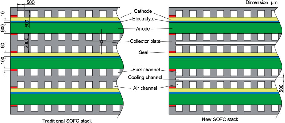
FIGURE 1. Geometric model size of SOFC.
The SOFC stack is heated to 650°C at a heating rate of 1°C/min. Then, the stack is operated at 650°C for 50,000 h. The assembly pressure is 0.1 MPa. During the operation, the creep effect at high temperatures is considered. In addition, the SOFC stack is assumed to be stress-free at the bonding temperature due to the stress relaxation at high temperatures. The residual stresses generated from bonding temperature to room temperature are also considered. The variations in thermal stresses, creep damage, and failure probability with time of the SOFC are calculated during the operation. Temperature-dependent thermophysical and mechanical properties are used, which are obtained from Wang et al. (2019).
Because the SOFC stack is a periodic repeating structure, the finite element model is simplified as a two-dimensional (2D) plain-strain model to save computing time. The finite element meshing for the conventional and new SOFC stacks is shown in Figure 2. The element width is 100 μm, and the element height is changed from 5 μm to 100 μm for different component thicknesses. The element type is a four-node plane reduction integrating element (CPS4R). During the stress analysis, in order to limit the model displacement and have freedom, the displacements of points A and C were restrained along the X-direction, and the displacements of points B and D were restrained along the Y-direction, as shown in Figure 2.
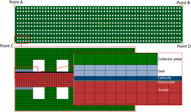
FIGURE 2. Finite element meshes of the SOFC stack.
The thermal stress is calculated by thermoelastoplastic analysis. For the operation stage of the SOFC stack, the total strain rate can be decomposed into four components as follows:
where
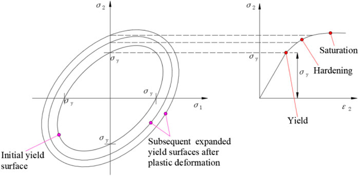
FIGURE 3. Isotropic hardening model.
Creep strain should be calculated accurately to predict the creep damage under a high-temperature state. The creep strain during the operation stage is calculated based on the Wen–Tu creep damage constitutive model (Wen et al., 2013):
where
The creep damage is calculated by the ductility exhaustion approach (Wen and Tu, 2014). In this approach, when the local creep strain accumulation reaches the creep ductility (creep fracture strain) value, the damage reaches the critical value. The ductility exhaustion approach is expressed in Eq. 5. In addition, the multiaxial creep fracture strain is calculated using the modified microscopic cavity growth model, as shown in Eq. 6
where
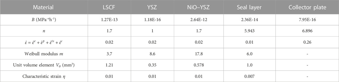
TABLE 1. Creep parameters of SOFC at 600°C.
Currently, the failure calculation of SOFC is mainly based on the Weibull statistical method. Weibull (1939) proposed a more flexible mathematical distribution model to fit the spread of brittle material failure strength. The traditional generalized form of the Weibull distribution model is usually expressed as (Anandakumar et al., 2010):
where P is the survival probability, σ0 is the characteristic strength that represents a scale parameter for the distribution, and m is the Weibull modulus. V0 is a reference volume linked to the characteristic strength. Vj is the volume of the material. The Weibull method shows that the failure probability is controlled by volume and applied stress. However, since the applied stresses in a SOFC are relaxed gradually during creep, it can also cause the growth of the pre-existing flaws and nucleation of new cavities and cracks by the creep damage. In this study, the failure probability is calculated based on the time-dependent failure probability model proposed by Zhang et al. (2018):
where η is the scale parameter that expresses the characteristic strain. The corresponding failure probability is obtained at each increment by importing the equivalent creep strain. Here, we assume that the Weibull parameters are the same before and after creep. The Weibull parameters of every part of the SOFC at 600°C are shown in Table 1 (Wang Y. et al., 2022).
The thermal stresses are generated because of temperature variation from room temperature to operation temperature. Figure 4 shows the contour distribution of CEEQ, creep damage, and failure probability after 50,000 h of operation. The maximum CEEQ and creep damage are all located at the sealing layer. The failure probability is located at the sealing layer between the anode and bipolar plate. The CEEQ, creep damage, and failure probability at other positions are very small. The distribution of creep damage is similar to CEEQ. The maximum creep damage and failure probability are 0.68 and 6.81E-4, respectively. The marginal area of the SOFC stack, especially in the sealing layer, is the key focus area.
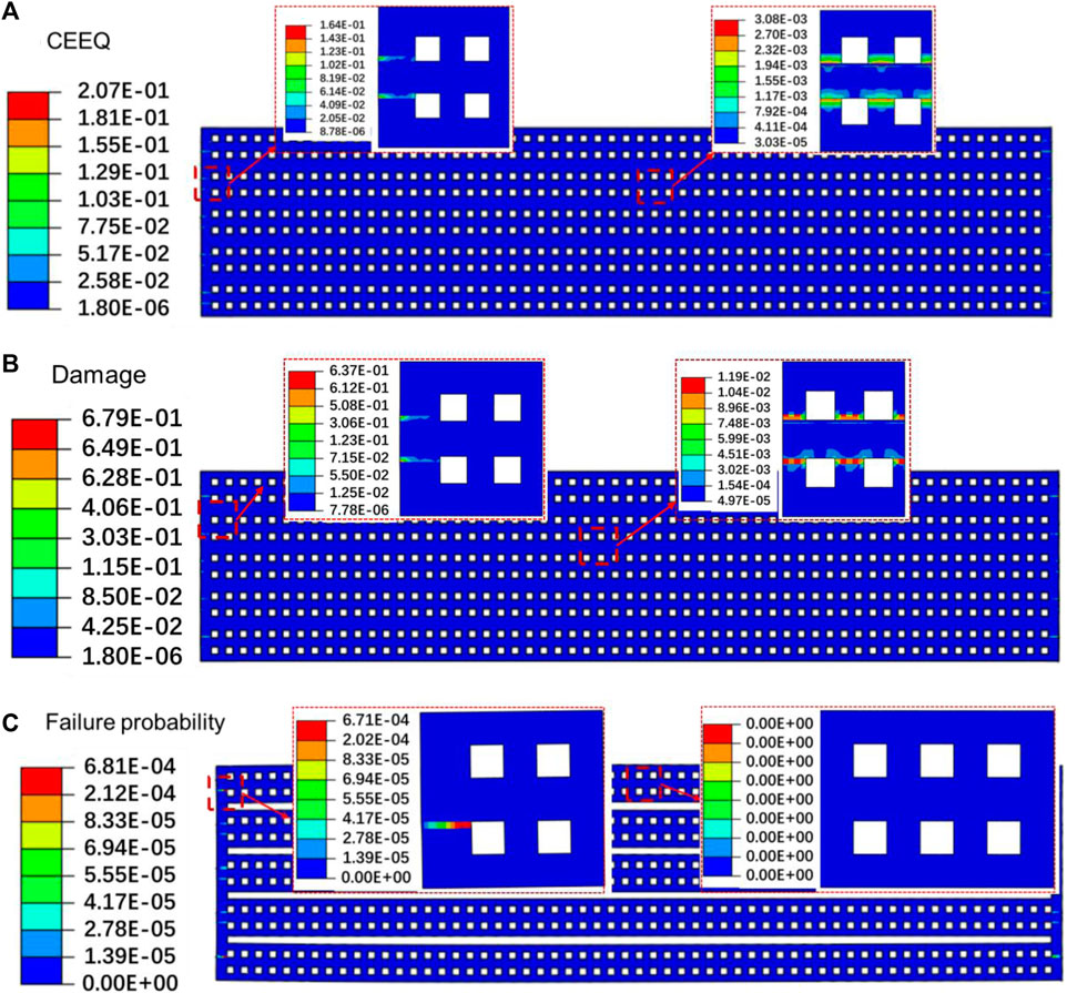
FIGURE 4. Contour distribution of CEEQ (A), creep damage (B), and failure probability (C) after 50,000 h of operation for the conventional SOFC stack.
In order to analyze the stress and damage in the marginal area clearly, Figure 5 shows the CEEQ, creep damage, and failure probability along path P1 after 50,000 h of operation. Here, path P1 is the distance from a collector plate→sealing layer→PEN→another collector plate. The maximum CEEQ and creep damage are all located in the sealing layer, while the maximum von Mises stress is located in the cell. The variation law of creep damage is the same as that of the CEEQ. The von Mises stress in the sealing layer is very small, so it indicates that the creep damage and failure probability are determined by the CEEQ rather than the von Mises stress.
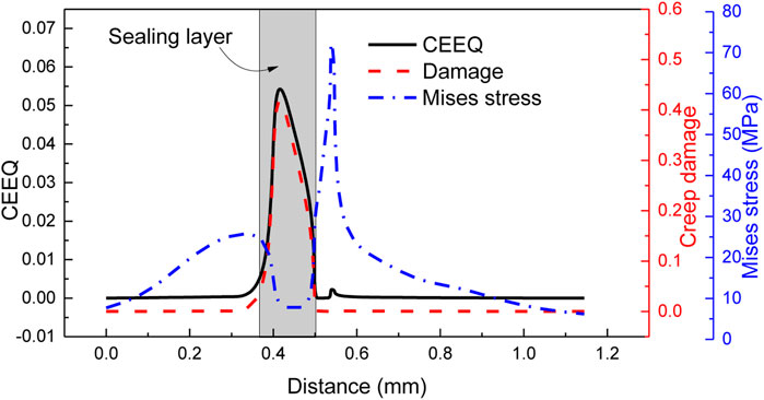
FIGURE 5. CEEQ, creep damage, and failure probability after 50,000 h of operation for the conventional SOFC stack.
Because the maximum creep damage and failure probability are all located in the sealing layer, variations occur in CEEQ, creep damage, von Mises stress, and failure probability during the operation with time of a node in the sealing layer, as shown in Figure 6. It obviously shows that the variation curves are divided into three stages. At stage I, the CEEQ, creep damage, and failure probability are greatly increased, while the von Mises stress is greatly decreased. At stage II, the CEEQ, creep damage, and failure probability are increased gradually, while the von Mises stress is decreased gradually. At stage III, the CEEQ, creep damage, and failure probability continue to increase at a smaller rate, while the von Mises stress decreases slightly. More attention should be paid to the thermal stress and creep damage of the SOFC stack in the early service period, especially within 10,000 h.
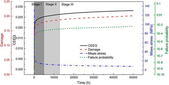
FIGURE 6. Variation in CEEQ, creep damage, von Mises stress, and failure probability of a node in the sealing layer during operation with time for the conventional SOFC stack.
The cooling channel was employed in the SOFC stack. Figure 7 shows the contour distribution of CEEQ, creep damage, and failure probability after 50,000 h of operation for the optimized SOFC stack with a cooling channel at 600°C. Compared with Figure 4, the CEEQ, creep damage, and failure probability were all decreased. The CEEQ and creep damage were decreased by 65% and 72%, respectively. The failure probability was decreased by 10 times. It is proved that the cooling channel can reduce creep damage and failure probability, thus increasing the service life at high temperatures.
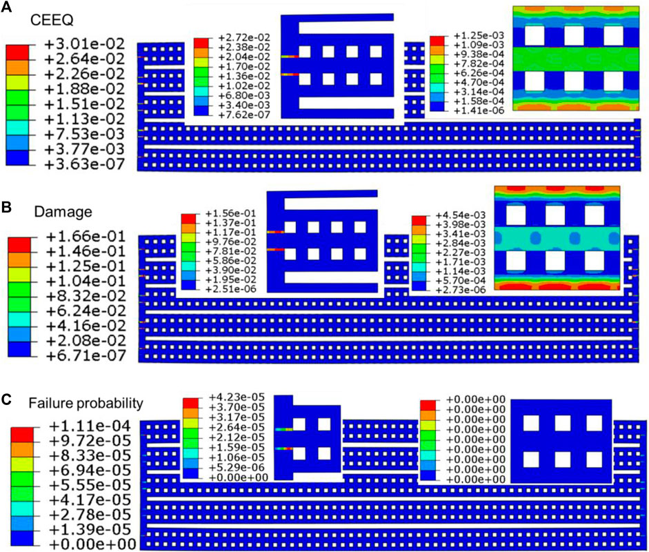
FIGURE 7. Contour distribution of CEEQ (A), creep damage (B), and failure probability (C) after 50,000 h of operation for the optimized SOFC stack.
The marginal area is the potential area for failure to occur, and the CEEQ, creep damage, and von Mises stress along path P1 in the marginal area after 50,000 h of operation for the optimized SOFC stack are shown in Figure 8. Similar to the conventional SOFC stack, the maximum CEEQ and creep damage are located in the sealing layer, where the von Mises stress is the minimum. Furthermore, the CEEQ and creep damage are the same for the two types of sealing layers (anode/bipolar plate and cathode/bipolar plate). The maximum CEEQ and creep damage are 0.021 and 0.135, respectively. The maximum von Mises stress is 69 MPa, which is located in the bipolar plate adjacent to the cathode side. The maximum von Mises stress is transferred from the cathode side to the bipolar plate side.
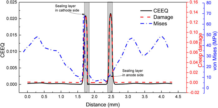
FIGURE 8. CEEQ, creep damage, and von Mises stress after 50,000 h of operation for the optimized SOFC stack.
Figure 9 shows the variation in CEEQ, creep damage, von Mises stress, and failure probability of a node in the sealing layer during operation with time for the optimized SOFC stack. The variation curves are also divided into three stages, which are similar to the curves of the conventional SOFC stack. The difference is that the CEEQ, creep damage, and failure probability have almost no changes at stages II and III. After 50,000 h of service, the creep damage and failure probability for the optimized SOFC stack are still smaller than those for the conventional SOFC stack. It indicates that the creep damage and failure probability mainly accumulate at the first stage within 6,000 h for the optimized SOFC stack. The attenuation of the SOFC stack due to creep damage is mainly concentrated in the early stage, and it is negligible in the late stage.
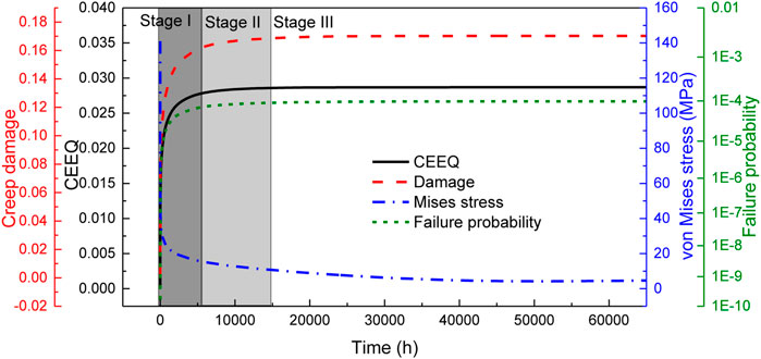
FIGURE 9. Variation in CEEQ, creep damage, von Mises stress, and failure probability of a node in the sealing layer during operation with time for the optimized SOFC stack.
Based on the aforementioned analysis, the cooling channel can reduce creep damage and failure probability of the SOFC stack. The temperature of the cooling channel is set at 600°C. In order to analyze the cooling channel temperature on the controlling effect, the CEEQ, creep damage, and failure probability of the optimized SOFC stack with a low cooling temperature (450°C) were also discussed. Figure 10 shows the CEEQ, creep damage, and failure probability after 50,000 h of operation for the optimized SOFC stack at a cooling temperature of 450°C. The distributions of CEEQ, creep damage, and von Mises stress are similar to those for the higher temperature (600°C). Compared to 600°C, the CEEQ and creep damage at 450°C decreased from 0.23 to 0.17 and from 0.14 to 0.11, respectively. The maximum von Mises stress is transferred from the bipolar plate side to the cathode side, and its value in the bipolar plate is increased.
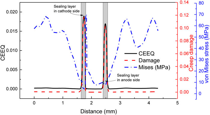
FIGURE 10. CEEQ, creep damage, and von Mises stress after 50,000 h of operation for the optimized SOFC stack at a low cooling temperature.
Figure 11 shows the variation in CEEQ, creep damage, von Mises stress, and failure probability of a node in the sealing layer during the operation with time for the optimized SOFC stack at a low cooling temperature. It can be seen that the variation curves are similar to those of the higher cooling temperature. The creep damage and failure probability have no changes in stage III. The creep damage and failure probability are also decreased with the increase in the cooling temperature.
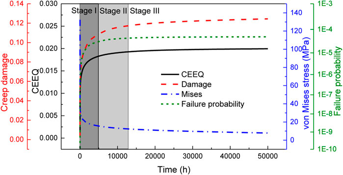
FIGURE 11. Variation in CEEQ, creep damage, von Mises stress, and failure probability of a node in the sealing layer during operation with time for the optimized SOFC stack at a low cooling temperature.
Table 2 lists the comparisons of maximum CEEQ, creep damage, and failure probability for the conventional and optimized SOFC stack. The maximum CEEQ, creep damage, and failure probability are all decreased by setting the cooling channel. Decreasing the cooling channel temperature is beneficial to further reducing the creep damage and failure probability. The cooling channel temperature can be realized by internal reforming or passing the cooling medium.
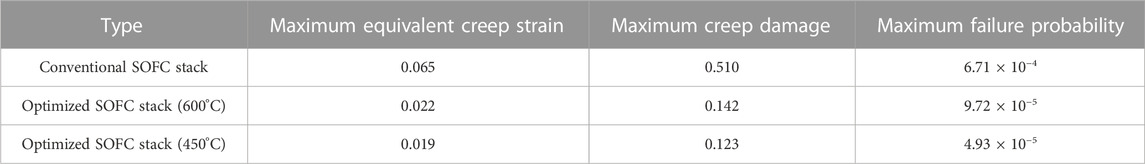
TABLE 2. Comparisons of maximum CEEQ, creep damage, and failure probability.
In this study, the thermal stress, creep damage, and failure probability of the SOFC stack were studied by simulation. The cooling channel was proposed to reduce the failure risk of the SOFC. The effects of cooling temperature were also discussed. The following conclusions can be obtained:
(1) The maximum creep damage and failure probability are located in the sealing layer. Larger CEEQ leads to a greater damage and failure risk after longtime service.
(2) Adding the cooling channel to the SOFC stack can reduce the creep damage and the failure probability because the internal temperature becomes more uniform.
(3) The attenuation of the optimized SOFC stack is mainly concentrated in the early stage, and the maximum von Mises stress is transferred from the cathode side to the bipolar plate side.
(4) The lower the cooling temperature, the better the cooling effect, and the lower the creep damage and failure probability.
The raw data supporting the conclusion of this article will be made available by the authors, without undue reservation.
YL: data curation, investigation, and writing–original draft preparation. XC and RL: methodology, logical structure, software, and validation. WJ: writing–reviewing and editing. All authors contributed to the article and approved the submitted version.
The authors gratefully acknowledge the support provided by the National Key R&D Program of China (2021YFB4001503).
The authors declare that the research was conducted in the absence of any commercial or financial relationships that could be construed as a potential conflict of interest.
All claims expressed in this article are solely those of the authors and do not necessarily represent those of their affiliated organizations, or those of the publisher, the editors, and the reviewers. Any product that may be evaluated in this article, or claim that may be made by its manufacturer, is not guaranteed or endorsed by the publisher.
Ananda kumar, G., Li, N., Verma, A., Singh, P., and Kim, J. H. (2010). Thermal stress and probability of failure analyses of functionally graded solid oxide fuel cells. J. Power Sources 195 (19), 6659–6670. doi:10.1016/j.jpowsour.2010.04.017
Chen, X., Wang, J., Yu, N., Wang, Y., Zhang, D., Ni, M., et al. (2023). A robust direct-propane solid oxide fuel cell with hierarchically oriented full ceramic anode consisting with in-situ exsolved metallic nano-catalysts. J. Membr. Sci. 677, 121637. doi:10.1016/j.memsci.2023.121637
Golkhatmi, S. Z., Imran Asghar, M., and Lund, P. D. (2022). A review on solid oxide fuel cell durability: Latest progress, mechanisms, and study tools. Renew. Sustain. Energy Rev. 161, 112339. doi:10.1016/j.rser.2022.112339
Gong, C., Tu, Z., and Chan, S. H. (2023). A novel flow field design with flow re-distribution for advanced thermal management in Solid oxide fuel cell. Appl. Energy 331, 120364. doi:10.1016/j.apenergy.2022.120364
Jiang, W., Luo, Y., Zhang, W., Woo, W., and Tu, S. T. (2015). Effect of temperature fluctuation on creep and failure probability for planar solid oxide fuel cell. J. Fuel Cell Sci. Technol. 12 (5), 051004. doi:10.1115/1.4031697
Jiang, W., Zhang, Y., Luo, Y., Gong, J., and Tu, S. (2013). Creep analysis of solid oxide fuel cell with bonded compliant seal design. J. Power Sources 243, 913–918. doi:10.1016/j.jpowsour.2013.06.096
Kim, D. H., Bae, Y., Lee, S., Son, J. W., Shim, J. H., and Hong, J. (2020). Thermal analysis of a 1-kW hydrogen-fueled solid oxide fuel cell stack by three-dimensional numerical simulation. Energy Convers. Manag. 222, 113213. doi:10.1016/j.enconman.2020.113213
Luo, Y., Jiang, W., Zhang, Q., and Hao, M. (2016). Effects of anode porosity on thermal stress and failure probability of planar solid oxide fuel cell with bonded compliant seal. Int. J. Hydrogen Energy 41 (18), 7464–7474. doi:10.1016/j.ijhydene.2016.03.117
Peksen, M. (2013). 3D thermomechanical behaviour of solid oxide fuel cells operating in different environments. Int. J. hydrogen energy 38, 13408–13418. doi:10.1016/j.ijhydene.2013.07.112
Peksen, M. (2011). A coupled 3D thermofluid–thermomechanical analysis of a planar type production scale SOFC stack. Int. J. hydrogen energy 36, 11914–11928. doi:10.1016/j.ijhydene.2011.06.045
Wang, W., Liu, J., Serbin, S., Chen, D., and Zhou, Hong (2022a). Thermal stress analysis for a typical planar anode-supported fuel cell stack. Sustain. Energy Technol. Assessments 54, 102891. doi:10.1016/j.seta.2022.102891
Wang, Y., Jiang, W., Luo, Y., Song, M., and Tu, S. T. (2022b). High temperature creep strength design and optimization of solid oxide fuel cell. Int. J. Hydrogen Energy 47 (2022), 21450–21461. doi:10.1016/j.ijhydene.2022.04.261
Wang, Y., Jiang, W., Luo, Y., Zhang, Y., and Tu, S. T. (2017). Evolution of thermal stress and failure probability during reduction and reoxidation of solid oxide fuel cell. J. Power Sources 371, 65–76. doi:10.1016/j.jpowsour.2017.10.034
Wang, Y., Jiang, W., Song, M., Zhang, Y., and Tu, S. T. (2019). Effect of frame material on the creep of solid oxide fuel cell. Int. J. Hydrogen Energy 44 (36), 20323–20335. doi:10.1016/j.ijhydene.2019.05.220
Wei, S. S., Wang, T. H., and Wu, J. S. (2014). Numerical modeling of interconnect flow channel design and thermal stress analysis of a planar anode-supported solid oxide fuel cell stack. Energy 69, 553–561. doi:10.1016/j.energy.2014.03.052
Weibull, W. (1939). A statistical theory of the strength of materials. Ing. Vet. Ak Handl. 151, 293–297.
Wen, J. F., and Tu, S. T. (2014). A multiaxial creep-damage model for creep crack growth considering cavity growth and microcrack interaction. Eng. Fract. Mech. 123, 197–210. doi:10.1016/j.engfracmech.2014.03.001
Wen, J. F., Tu, S. T., Gao, X. L., and Reddy, J. N. (2013). Simulations of creep crack growth in 316 stainless steel using a novel creep-damage model. Eng. Fract. Mech. 98 (1), 169–184. doi:10.1016/j.engfracmech.2012.12.014
Yang, T., Fan, Y., Liu, J., Finklea, H., Lee, S., Guan, B., et al. (2022). Multiphysics modeling of SOFC performance degradation caused by interface delamination and active layer cracking. Int. J. hydrogen energy 47, 41124–41137. doi:10.1016/j.ijhydene.2022.09.194
Yu, C. Z., Jiang, W., Tu, S. T., Wang, C. L., and Chen, Cheng (2018). Effect of operating temperature on creep and damage in the bonded compliant seal of planar solid oxide fuel cell. Int. J. Hydrogen Energy 43, 4492–4504. doi:10.1016/j.ijhydene.2018.01.048
Yu, C. Z., Jiang, W., Tu, S. T., Wen, J. F., and WanchuckWoo, (2014). Using short-time creep relaxation effect to decrease the residual stress in the bonded compliant seal of planar solid oxide fuel cell-A finite element simulation. J. Power Sources 255, 108–115. doi:10.1016/j.jpowsour.2013.12.105
Yu, C. Z., Jiang, W., Tu, S. T., Zhang, Xian-Cheng, and Ye, You-Jun (2017). Creep crack growth behavior analysis of the 9Cr-1Mo steel by a modified creep-damage model. Mater. Sci. Eng. A 708, 68–76. doi:10.1016/j.msea.2017.09.112
Zhang, D., Wang, Y., Peng, Y., Luo, Y., Tong, L., He, W., et al. (2023). Novel high-entropy perovskite-type symmetrical electrode for efficient and durable carbon dioxide reduction reaction. Adv. Powder Mater. 2 (4), 100129. doi:10.1016/j.apmate.2023.100129
Zhang, Q., Xie, K., Luo, Y., Zhang, Y. C., and Jiang, W. C. (2021). Mismatch effect of material creep strength on creep damage and failure probability of planar solid oxide fuel cell. Int. J. Hydrogen Energy 47 (4), 2673–2684. doi:10.1016/j.ijhydene.2021.10.185
Zhang, X., Tong, Y., Tong, L., Zhang, D., Yu, N., Zhou, J., et al. (2022). Robust Ruddlesden-Popper phase Sr3Fe1.3Mo0.5Ni0.2O7-δ decorated with in-situ exsolved Ni nanoparticles as an efficient anode for hydrocarbon fueled solid oxide fuel cells. SusMat 2, 487–501. doi:10.1002/sus2.58
Zhang, Y. C., Jiang, W., Tu, S. T., and Wen, J. F. (2014). Simulation of creep and damage in the bonded compliant seal of planar solid oxide fuel cell. Int. J. Hydrogen Energy 39, 17941–17951. doi:10.1016/j.ijhydene.2014.08.130
Zhang, Y. C., Lu, M. J., Jiang, W., Tu, S. T., and Zhang, X. C. (2019). Effect of the geometrical size on time dependent failure probability of the solid oxide fuel cell. Int. J. Hydrogen Energy 44, 11033–11046. doi:10.1016/j.ijhydene.2019.02.155
Keywords: solid oxide fuel cell, creep damage, failure probability, structural optimization, finite element analysis
Citation: Luo Y, Chen X, Liu R and Jiang W (2023) Effects of a cooling channel on the creep damage and failure probability of planar solid oxide fuel cells. Front. Mater. 10:1238559. doi: 10.3389/fmats.2023.1238559
Received: 12 June 2023; Accepted: 18 July 2023;
Published: 02 August 2023.
Edited by:
Jiantie Xu, South China University of Technology, ChinaReviewed by:
Tong Liu, Wuhan Institute of Technology, ChinaCopyright © 2023 Luo, Chen, Liu and Jiang. This is an open-access article distributed under the terms of the Creative Commons Attribution License (CC BY). The use, distribution or reproduction in other forums is permitted, provided the original author(s) and the copyright owner(s) are credited and that the original publication in this journal is cited, in accordance with accepted academic practice. No use, distribution or reproduction is permitted which does not comply with these terms.
*Correspondence: Yun Luo, bHVveXVuMTAwM0AxNjMuY29t
Disclaimer: All claims expressed in this article are solely those of the authors and do not necessarily represent those of their affiliated organizations, or those of the publisher, the editors and the reviewers. Any product that may be evaluated in this article or claim that may be made by its manufacturer is not guaranteed or endorsed by the publisher.
Research integrity at Frontiers
Learn more about the work of our research integrity team to safeguard the quality of each article we publish.