 Martin Nguyen
 Zhiming Liang1
 Yangyang Wang
 Adrian Gestos
 Chunmei Ban
- 1Paul M. Rady Department of Mechanical Engineering, University of Colorado Boulder, Boulder, CO, United States
- 2KULR Technology Group, Inc., San Diego, CA, United States
- 3Materials Science and Engineering Program, College of Applied Sciences and Engineering, University of Colorado Boulder, Boulder, CO, United States
Thick LiFePO4 (LFP) cathodes offer a promising solution to increasing the areal capacity and reducing the cost of Li-ion batteries while retaining the qualities intrinsic to LFP, including long cycle lifetimes and thermal stability required for electric vehicles and stationary energy storage applications. However, the primary challenges of thick LFP cathodes are poor rate capability and cycling stability due to LFP’s electronically insulating material property, poor electronic conductivity, and long diffusion length at high electrode thicknesses. Herein, we propose an electrode architecture composed of vertically aligned carbon fibers (CFs) attached to a plasticized current collector (PCC) to promote rate capability, cycle life, and further enhance the safety of thick LFP cathodes. The effectiveness of the CF-PCC architecture is demonstrated by electrochemical analysis with a good areal capacity of 3.5 mA cm-2, excellent cycling stability at C/3, and good rate capability up to 1C. These results are confirmed by investigating the architecture’s impact on ionic diffusivity via electrochemical impedance spectroscopy (EIS) and cyclic voltammetry (CV) compared to the conventional slurry cast LFP cathode.
1 Introduction
The improvement of energy density of Li-ion cells is highly researched across the globe to meet increasing energy storage needs (Goodenough and Park, 2013). To achieve this, one could develop electrode materials that operate at higher voltages or have higher charge densities. However, this often requires discovering new battery chemistries which has proven to be extremely difficult. Another method is to optimize the manufacturing process of Li-ion cells to decrease the use of non-capacitive components such as the separator and current collector. Thick electrodes offer a promising solution to increase energy density as they minimize the ratio of non-capacitive components in each cell, as well as simplifying the manufacturing process by requiring fewer cutting and assembling steps (Singh et al., 2015). For reference, conventional Li-ion cells contain electrodes that are of 50–70 μm thickness (Singh et al., 2015; Arnot et al., 2022; Zheng et al., 2023).
However, rate-capability is a roadblock for thick electrodes. Thick electrodes have a longer diffusion pathway which inhibits Li-ion transport as well as higher internal resistance, thus causing severe capacity decay at higher C-rates (Zheng et al., 2012; Zhao et al., 2015). Furthermore, thicker electrodes have less robust mechanical integrity. Conventional electrodes are made by coating an aqueous slurry of active material onto a metallic current collector. Increasing the thickness using this manufacturing method would introduce large cracks in the electrode laminate during the drying process due to uneven evaporation (Evanoff et al., 2012). In addition, active materials are known to expand and contract upon lithiation and delithiation which accumulates stress. This stress is hard to release in thick electrodes inevitably leading to fracture in the electrode laminate. These fractures can cause particle isolation, therefore leading to capacity fade and increased impedance of the electrode (Park et al., 2010).
Other groups have investigated new fabrication methods and architectures to address these issues such as using conductive carbon frameworks from natural wood and 3D printing (Chen et al., 2017; Wei et al., 2018). Here, we report an electrode architecture that utilizes a 3D conductive carbon fiber (CF) framework attached to a plasticized current collector (PCC), as opposed to current state-of-the-art monolayer Al current collectors. The carbon fiber acts as an extension of the current collector; it has good electronic conductivity (Xi and Chung, 2019), providing a pathway for electrons throughout the entire thickness of the electrode. This connection would then mitigate the issue of high internal resistance in thick electrodes. The morphological and electrochemical properties of the CF-LFP cathodes are compared to a thick cathode manufactured using the conventional slurry cast method.
Tortuosity is also a critical factor in Li-ion electrode performance as it is inversely related to ionic diffusivity (Thorat et al., 2009). Since the carbon fibers are vertically aligned, this allows for a highly ordered, low tortuous electronic connection throughout the entire thickness of the electrode. Other carbon fiber frameworks enable thick electrode designs but are often randomly interwoven and thus introduce tortuosity which decreases Li-ion diffusivity (Chen et al., 2017; Li et al., 2021). In this study, the 3D architecture is utilized to improve an LFP cathode. Furthermore, porosity is a critical factor in the performance of Li-ion electrodes. A highly porous electrode promotes ionic diffusion with greater open access to the liquid electrolyte, however this is at the cost of poorer electronic connection between particles (Singh et al., 2016; Heubner et al., 2019; Elango et al., 2021). We demonstrate that the 3D conductive architecture is successful in improving the rate capability of LFP, which has intrinsically low-rate performance due to its unique two-phase insertion reaction (Yuan et al., 2011). This new architecture enhances ion diffusion with the framework’s unique verticality and promotes electronic conductivity by extending electronic pathways throughout the bulk of the electrode.
State-of-the-art current collectors simply use Al foil due to its good electronic conductivity, cost, and passivation layer when coupled with LiPF6 electrolyte, which makes the electrolyte/current collector interface stable at higher voltages (Braithwaite et al., 1999; Whitehead and Schreiber, 2005). However, Al current collectors are susceptible to short circuits caused by mechanical damage. The inclusion of a PCC introduces a new mechanism to increase safety. In short, the polymer core shrinks away from a mechanical defect and thus breaks the short circuit to prevent thermal runaway (Pham et al., 2021). The PCC is comprised of a ∼8 μm polymer core with a ∼0.5 μm Al coating. The polymer core is lighter than Al, and the Al coating allows the PCC to retain the passivation layer typical of Al current collectors. Thus, the inclusion of PCC enables the novel design to not only possess high energy density and rate capability, but also increased safety compared to conventional cathodes.
2 Experimental section
2.1 Materials and electrode preparation
The vertically-aligned carbon fiber substrate was created by carbonizing pitch fibers. During carbonization, the temperature was carefully controlled to form amorphous carbon between the carbon fibers, which helped to hold them vertically. The carbon fibers were manufactured at our collaborator’s facility (KULR Technology Group). Then, the 3D carbon fiber substrate was secured to the current collector with a carboxyl-methyl cellulose (CMC) to enhance the vertically aligned architecture. The pitch-based CF was provided by the KULR Technology Group and the PCC by the Soteria Battery Innovation Group. The resulting CF-PCC substrate is then cut into 12 mm diameter discs to be loaded with the cathode material.
The materials to produce the cathode included carbon coated micro LFP particles (MTI Corp., 10 μm diameter) as active material without any further treatment, TIMCAL SUPER C45 carbon black (CB, 100–200 nm diameter) (MSE Supplies) as the conductive additive, and polyvinylidene fluoride (PVDF) (Sigma Aldrich) as the binder. The cathode material is first prepared by mixing the CB and LFP using a FlackTek DAC 330–100 Pro SpeedMixer at 500 RPM for 5 min. The PVDF binder is dissolved in n-methyl-2-pyrrolidone (NMP) (Sigma Aldrich) with a concentration of 5 wt% and is subsequently mixed at 2000 RPM for 10 min with the LFP-CB mixture to obtain a viscous slurry. The composition of the slurry by weight is 70:20:10 of LFP:CB:PVDF. The slurry is loaded into the CF-PCC discs via centrifuge to form complete LFP cathodes using the FlackTek SpeedMixer. This was achieved by placing the CF-PCC disc in a mixing bottle which is held at an angle in the SpeedMixer, pouring the slurry on top of the disc, and subsequently loaded via centrifuge at 2000 RPM for 5 min. The cathodes were first dried at 60°C for 4 h under ambient pressure and then dried in a vacuum oven at 90°C overnight to ensure slow solvent evaporation followed by complete removal of water. The conventional slurry cast LFP cathodes used as comparison were purchased from MTI Corp as is, meaning no additional synthesis steps aside from cutting and drying under vacuum at 90°C overnight were used to obtain the slurry cast cathodes. These conventional cathodes contain 93% wt. LFP with the remaining weight as PVDF and carbon.
The mass of LFP in the CF-LFP electrodes were weighed using a mass balance and the %wt of LFP in the slurry. The areal loading of all conventional slurry cast cathodes was approximately 10.6 mg cm-2 or 12.0 mg per cell, while the areal loading for the CF-LFP cathodes evaluated with galvanostatic cycling were approximately 22.2 mg cm-2, or 25.1 mg per cell. The areal capacity was calculated by dividing the measured capacity by the area of the cathode. The CF-LFP cathodes tested with electrochemical impedance spectroscopy (EIS) and cyclic voltammetry (CV) were fabricated with areal loadings of approximately 11.0 mg cm-2 to ensure fair comparison with the conventional slurry cast cathodes.
2.2 Morphological and structural characterization
Scanning electron microscopy (SEM) images were taken using a Hitcahi SU3500 microscope with a 10 kV electron beam. Micro X-ray computed tomography (XRCT) scans were performed using a Zeiss Xradia 520 Versa Microscope. Scans included 1601 projections with a ×20 objective, at 50 kV for the bare CF substrate and 80 kV for the loaded CF-LFP cathode. Image analysis and visualization was performed using Dragonfly (Object Research Systems). Image noise was reduced using a Gaussian filter. X-ray diffraction (XRD) was performed using a Rigaku SmartLab 9 kW X-ray Diffractometer using Cu K-α radiation (1.54 Å). XRD data was analyzed and refined using Rigaku SmartLab II software. Energy dispersive x-ray spectroscopy (EDS) was performed on a JEOL JSM-701F Field Emission Scanning Electron Microscope.
2.3 Electrochemical characterization
Coin cells were assembled within an argon glove box. EIS and CV experiments were performed on a BioLogic VMP-3e Potentiostat and galvanostatic cycling on a Neware Battery Testing System. Li-metal foil (Sigma Aldrich) of 150 μm thickness was used as the anode and reference electrode for EIS and galvanostatic cycling experiments. For post-cycling EIS analysis, the cells were disassembled, anode and cathode cut in half, and reassembled into a symmetric cell configuration. Glass microfiber filters (Whatman, Millipore Sigma) were used as the separator for all measurements of the CF-LFP cathode and conventional slurry cast cathodes. Glass fiber separators were used due to their ability to intake the appropriate amount of liquid electrolyte suitable for the CF-LFP cathode. The glass fiber separator was used for the conventional slurry cast cells for fair comparison. The electrolyte used was 1.2 M LiPF6 in EC:EMC (3:7 wt. ratio) (Tomiyama Pure Chemical Industries), with around 80 μL of electrolyte in each cell which was calculated using the volumetric pore size of the cathode and glass fiber membrane. Charge and discharge cycles were performed on a Neware CT-4008T Battery Testing System. The C-rates for each cell were calculated using the theoretical capacity of LFP (170 mAh g-1). EIS measurements and CV measurements were carried out using a BioLogic VMP-3e Potentiostat.
3 Results and discussion
3.1 Electronically conductive architecture with controlled porosity
The conductive framework used as the current collector and scaffold for the thick LFP cathode is made of pitch-based carbon fibers of 450 μm length glued onto the 10 μm thick PCC with a CMC resin. Information about the synthesis of the carbon fiber composite substrate is detailed in the Methods section. The carbon fibers have an average diameter of 9 μm with a desired spacing of 30 μm. SEM and XRCT were used to characterize the morphology and 3-dimensional structure of the composite substrate as shown in Figure 1. Figures 1A, B are top and cross-sectional SEM images respectively, showing that the CFs are vertically aligned and homogenous in both diameter and height. Figures 1C, D are three dimensional orthographic projections of the conductive framework obtained using XRCT. The PCC substrate, which the CFs are anchored to, can be seen in the bottom of the XRCT images from Figures 1C, D. The volume fraction of the CFs calculated from the XRCT image shown in Figures 1C, D is 9.1%, which agrees with the volume fraction of 9.6% calculated by using mass and density of pitch CFs. Perfect alignment of the CFs is practically difficult due to the low volume fraction of CFs.
FIGURE 1. Morphology of CF substrate. (A,B) SEM cross-sectional image of the carbon fiber substrate to visualize the verticality and ordered structure, (C,D) XRCT images to visualize the framework within the bulk of the substrate.
CFs were fabricated using a carbonization process of pitch polymer. The crystalline structure was confirmed by using X-ray diffraction (XRD). The XRD pattern of the CFs is plotted in red in Figure 2. The peaks are indexed to graphitic structure (NIST ICSD #260570). The composition and structure of the PCC are also characterized via XRD, which is plotted in black in Figure 2. The peaks are indexed to both Al (NIST ICSD #4313217) and graphite as shown in the inset of Figure 2. Furthermore, the CF substrates, made of CFs and the PCC, are characterized and plotted in blue in Figure 2. As expected, the complete substrate’s plot is a superposition of its components’ XRD patterns. XRD scans of the complete substrate and its decoupled components contain expected characteristic peaks of aluminum (2θ = 25°, 38°, 65°, and 78°) and graphite (2θ = 26°, 42°, 53° and 77°). The presence of the graphitic peaks in the inset XRD plot of the PCC indicates a graphitic structure which contributes to its ability to conduct electrons between the aluminum coating of the plasticized current collector. Other graphitic peaks may be overshadowed by the other components of the PCC such as the polymer and aluminum. For the application of thick LFP cathodes, the verticality, ordered arrangement, and intrinsic electronic conductivity of the resulting CF substrate can largely improve the electronic conductivity, structural stability, and ionic diffusivity.
FIGURE 2. XRD pattern of the carbon fiber substrate (blue), along with its components of carbon fiber (red) and the Soteria PCC (black). The inset reveals the presence of graphitic and aluminum peaks in the PCC, zoomed in between 2θ = 40° and 80°.
3.2 Ultrathick LFP cathodes
The CF-LFP cathode is fabricated by loading an LFP slurry comprised of LFP, carbon black (CB), and polyvinylidene fluoride (PVDF) by 70:20:10 wt% via centrifugal force into the carbon fiber substrate. The CF-PCC XRD patterns of the loaded CF-LFP cathode indicate that no side reactions occur upon fabrication (Supplementary Figure S1). The resulting CF-LFP cathode was measured to be approximately 500
After loading the composite substrate with LFP, SEM reveals that the vertically aligned orientation of the CFs is retained as shown in Figures 3A, B. Top-view morphology analysis reveals the presence of primary and secondary pores on the surface, including macro gaps between carbon fibers and micro gaps between particles as seen in Figures 3D, E. While 5–10 μm cracks are observed, these are not as large as the mm-scale cracks observed on conventional slurry cast cathodes of comparable thicknesses (Lee et al., 2018; Sahore et al., 2020). The thickness of the CF-LFP cathode was measured to be around 500 μm. SEM confirms that most of the active material is hosted within the CF forest rather than being superficially loaded. Furthermore, the presence of CFs on the surface confirms electronic connection throughout the entire thickness of the cathode as shown in Figure 3D. For comparison, SEM top and cross-sectional images of the conventional slurry cast cathode are included in Figures 3C, F.
FIGURE 3. SEM Morphology of the CF-LFP cathode. (A,B) Cross-sectional images of the loaded carbon fiber cathodes revealing uniform particle distribution across the entire thickness of the electrode. (C) Cross-sectional SEM image of the conventional slurry cast LiFePO4 cathode. (D,E) Top view SEM images showing no superficial loading of active material LiFePO4. (F) Top view SEM image of the conventional slurry cast cathode.
XRCT was used to quantify the porosity of the loaded CF-LFP cathode as well as to qualitatively evaluate how well the active material was loaded into the 3D architecture without damaging the sample to obtain a cross sectional view. Due to the large difference in atomic number Z between the relatively high Z LFP microparticles and lower Z graphitic carbon fiber, carbon black and PVDF, the heavy and light materials can be resolved in XRCT as shown in Figure 4A. The LFP material is shown as bright white with the carbon materials as black and gray (Figure 4A). Figure 4B shows a segmented image with only the LFP represented, which is used to measure the volumetric fraction of LFP active materials (38.7%). Thus, the use of XRCT allows us to segment the LFP active material from the CB, CF, and PVDF; this allows us to report the volume fraction of LFP in addition to the electrode porosity. The electrode porosity can be directly obtained by measuring the occupied volumetric space from Figure 4A and subtracting from 100% and was measured to be 32.6%, which agrees with reported porosity values of 35%–55% from the literature (Thorat et al., 2006; Fongy et al., 2010; Mastali Majdabadi et al., 2015; Bao et al., 2017; Liu et al., 2019; Zhu et al., 2020; Elango et al., 2021; Guo et al., 2021; Wu et al., 2021). To confirm CF verticality within the bulk electrode, we can assign bright white to carbon and black to LFP as shown in Figure 4C. Furthermore, the conductive carbon black additive can be seen using this characterization technique as a darker powder in Figure 4A or as a lighter powder in Figure 4C. An exact segmentation and quantification of the carbon-based materials from XRCT image was not possible due to their similarity in grayscale.
FIGURE 4. 3D Bulk Morphology of CF-LFP cathode. (A) 3D XRCT illustration of the CF-LFP cathode to study electrode porosity and loading distribution of the active material. Here, the heavier LFP particles are a bright white compared to the darker CFs and CB particles. (B) 3D XRCT illustration, derived from (A), showing only the active material LFP. (C) 3D XRCT illustration of the CF-LFP cathode where the colors are inverted from (A) to better show the CF verticality.
3.3 Enhanced Li-ion diffusion across the thick electrode
The CF-LFP cathode not only provides a robust electronic connection but also facilitates enhanced Li-ion diffusion throughout the thickness of the electrode. A conventional slurry cast cathode of comparable thickness can achieve a higher theoretical capacity due to the absence of CF but suffers from extreme cracking and delamination as described in the introduction. The conductive CF architecture is introduced to compensate for the poorer electronic connectivity between active material particles and explains the enhanced performance of the cathode. To investigate the electrochemical performance of the CF-LFP cathode, 2032-coin cells were fabricated with a glass fiber separator, Li-metal anode, and 1.2 M LiPF6 liquid electrolyte. Coin cells using the conventional slurry cast LFP cathode were also fabricated using the same glass fiber separator and liquid electrolyte that were used as a baseline comparison for the CF-LFP cathode.
The improvement in charge transfer resistance and ionic diffusion of the CF-LFP cathodes was assessed using electrochemical impedance spectroscopy (EIS) in a half cell configuration. First, all cells were cycled at C/10 for 3 cycles and then cycled at C/3 for 50 cycles. EIS measurements were taken every 10 cycles at C/3, and held at 50% state of charge for the CF-LFP and conventional slurry cast cathodes, as shown in Figures 5A, B respectively. The semi-circle in the resulting Nyquist plots contain information regarding the cell’s ohmic resistance (
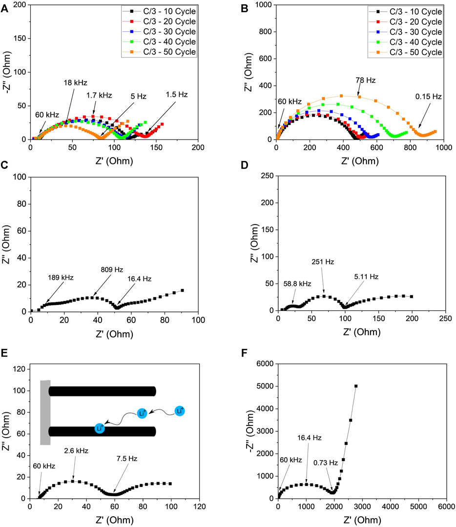
FIGURE 5. EIS study of the CF-LFP and conventional slurry cast cathodes. Nyquist profiles showing impedance evolution with increasing cycle number at a current density of C/3 in a half-cell configuration with a Li-metal anode for (A) the CF-LFP cathode and (B) the conventional slurry cast cathode. Nyquist plots of the harvested (C,D) Li-metal, and (E,F) CF-LFP and conventional slurry cast cathodes respectively from the aged half-cells (A,B) in a symmetric cell configuration to decouple cathode impedance contributions from the Li-metal anode.
To study the impact of the Li-metal on the impedance evolution, these cells were disassembled, and the cathode and Li-metal anodes were collected. The Li-metal and cathodes were then used to assemble symmetric cells for EIS measurements to examine individual cathode contributions to the results from Figures 5A, B. Nyquist plots are shown in Figures 5C, D for the Li-metal symmetric cells harvested from the conventional slurry cast cathode and CF-LFP cathode, respectively. Li-metal from the conventional slurry cast cathode has higher impedance compared to the CF-LFP counterpart. EDS mapping was also conducted to confirm that there was no iron deposition on the Li-metal from the cathodes as shown in Supplementary Figure S2. The symmetric cells of cathodes were used in EIS to confirm the charge transfer behavior for the cathodes. A large impedance was observed for the conventional slurry cast cathode (Figure 5F), in sharp contrast to the CF-LFP cathode (Figure 5E). Moreover, the Nyquist plots of the symmetric cathode cells show a stark contrast in Warburg impedance behavior. While the Warburg element of the conventional slurry cathode exhibits semi-infinite linear diffusion, the carbon fiber cathode exhibits finite length diffusion. This is most likely due to the CF framework’s ability to promote ionic diffusion along the thickness of the electrode (inset of Figure 5E) and allow facile electron transport throughout the bulk of the electrode, as ionic and electronic pore movement are coupled. These factors result in a lower ionic diffusion distance; an effect like that of a rotating disk electrode.
The transmission line model is a useful extension of the Randles model specifically for thick electrodes that includes ionic resistance in pores (
CV was performed on the coin cells to investigate Li+ diffusivity of the CF-LFP cathode, where the counter electrode is Li-metal as shown in Figures 6A, B. Both cells are of similar mass loading (11.0 and 10.6 mg cm-2 for the CF-LFP and conventional slurry cast cathode respectively), to compare Li+ diffusion per active material. In this measurement, voltage limits were set between 2–4 V with increasing scan rates from 0.07 mV s-1 up to 0.2 mV s-1. LFP CV profiles show one anodic peak (charge) and one cathodic peak (discharge) whereby in perfect conditions both peaks are closest to the open circuit voltage of 3.43 V (Yu et al., 2007). The oxidation and reduction peaks of the Fe2+/Fe3+ redox couple occur around 3.7 V and 3 V vs. Li/Li+ respectively, indicating Li+ transport is limited, and the redox reaction occurs under non-equilibrium conditions. It can be seen for both conventional slurry cast and CF-LFP cathodes that there is one oxidation and one reduction peak, however the voltage shifts are much more severe in the conventional slurry cast cathode compared to the CF-LFP cathode. Furthermore, the conventional slurry cast cathode’s cathodic peak cannot be resolved, most likely due to insulation issues regarding thick electrodes as discussed in the introduction. When increasing the scan rate, both cathodes’ redox peak disparities increase, however the peak disparity for the conventional slurry cast cathode becomes so severe that the peak current density cannot be resolved (Figure 6A). This indicates the Li+ diffusion capability is much more limited in the conventional slurry cast cathode compared to the CF-LFP cathode, which is supported by the CF architecture’s ability to promote a continuous electronic connection throughout the entire thickness of the electrode and the CF architecture’s intrinsic verticality to promote low tortuosity from Figures 3, 4 (Yu et al., 2007; Park et al., 2011; Zhang et al., 2013). Furthermore, the conventional slurry cast cathode’s peak current is an order of magnitude lower than the CF-LFP cathode’s at all scan rates. This suggests that the CF architecture enhances reaction kinetics which may lead to highly reversible cycling performance at elevated current densities.
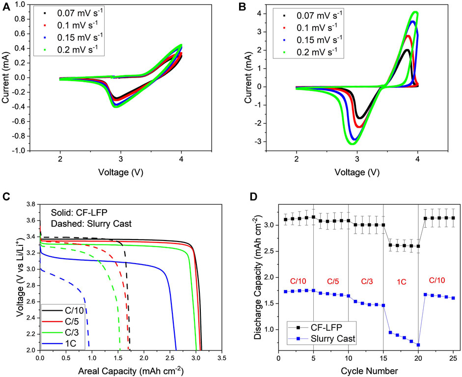
FIGURE 6. Electrochemical data of the conventional slurry-casted cathodes’ and the CF-LFP (A,B) cyclic voltammogram at increasing voltage sweeps respectively, (C) voltage profile as a function of areal capacity, (D) rate capability performance at current densities of C/10, C/5, C/3 and 1C.
Finally, galvanostatic cycling was performed to measure the life cycle performance and rate capability of the CF-LFP cathode. The discharge performance of the CF-LFP and conventional cathode was evaluated using loading parameters and cell configuration detailed in the experimental section (Figure 6C). The specific capacity at C/3 was measured to be 146 mAh g-1 for the CF-LFP cathode, which is in agreement with the theoretical capacity of LFP (170 mAh g-1) (Lung-Hao Hu et al., 2013; Zhao et al., 2017). The fully loaded CF-LFP possesses a high areal capacity of 3.2 mAh cm-2. In comparison to the conventional slurry cast cathode, the CF-LFP cathode possesses better capacity retention at higher currents despite being 4.5x thicker. Performance is similar at lower current densities with a 2.6% capacity drop for the CF-LFP cathode and a 2.8% capacity drop for the conventional slurry cast cathode at C/10. However, the discrepancy in performance becomes more apparent at C/3 and 1 C, with a capacity drop of 3.2% and 16.9% respectively for the CF-LFP cathode, and a capacity drop of 15.1% and 52.4% respectively for the conventional slurry-casted cathode. Furthermore, ohmic polarization increases at a higher rate for the conventional slurry cast cathode than the CF-LFP cathode at higher current densities. At lower current densities, both cathodes maintain a discharge voltage plateau close to the operating 3.4 V intrinsic to LFP. However, at 1 C the conventional slurry cast cathode experiences a 0.6 V drop while the CF-LFP cathode only drops 0.3 V. These results agree with the EIS measurements as impedance has been shown to increase substantially over continued cycling.
Capacity retention at elevated current densities was evaluated by cycling at C/10, C/5, C/3, and 1 C for 5 cycles each and recording the discharge capacities (Figure 6D). The error bars include the standard deviation of discharge capacities from 3 separate cells. A rate capability plot with the corresponding gravimetric capacities of the CF-LFP and the conventional slurry-casted cathodes are reported in the Supplementary Material (Supplementary Figure S6). It can be clearly seen that the CF framework greatly improves the rate capability despite the large difference in thickness between the cathodes. The CF-LFP cathode is also shown to possess superior life cycle performance C/3 with an 88.7% capacity retention compared to the conventional slurry cast cathode capacity retention of 12.1% at the end of 100 cycles (Supplementary Figure S7 and Supplementary Figure S8). These results are supported by the increasing peak disparity as discussed with CV. The polymer core of the PCC seems to have no detrimental effect on the performance of the electrode during cycling. Recent progress of thick electrodes, with C-rate and corresponding areal capacity, is included for comparison with this work in Supplementary Table S1.
4 Conclusion
In summary, we report a novel electrode architecture featuring a 3D conductive framework of vertically aligned carbon fibers to host the LFP active material. The ordered morphology of the CF-LFP cathode enabled by the CF architecture was analyzed and confirmed using XRCT. The architecture enables a high areal capacity of 3.2 mAh cm-2 with good rate performance, low ohmic polarization, and good life cycle performance at moderate current densities in comparison to the conventional slurry cast cathode. The improved performance is attributed to the CF framework’s ability to facilitate the electronic conductivity across the electrode’s thickness and enhance Li-ion diffusion through its vertical consistency. EIS measurements reveal unique characteristics such as much lower charge transfer resistance and drastically different Warburg impedance when comparing the CF-LFP cathode and the conventional slurry cast cathode, which are evidence of improved ion kinetics enabled by the CF framework. CV measurements further confirm the improvement of the CF-LFP’s cathode rate capability in comparison to the conventional slurry-casted cathodes, as performance is superior at all scan rates. To gain a comprehensive understanding of the CF framework’s impact on ion transport, further investigations into the electrode-electrolyte wetting behavior are crucial. This research should encompass the study of contact angles, surface tension, and the influence of various electrode materials and coatings. These insights hold the potential to optimize the performance of the CF framework in ion transport applications, fostering advancements in this field.
Data availability statement
The original contributions presented in the study are included in the article/Supplementary Material, further inquiries can be directed to the corresponding author.
Author contributions
MN: experiment and original draft preparation; ZL: experiment; KG and YW: morphology characterization and editing; AG: X-ray CT scan characterization and editing; MM: resources; CB: experimental design, methodology, supervision, and editing. All authors contributed to the article and approved the submitted version.
Funding
The work related to micro XRD CT scan was supported, in part, by the U.S. National Science Foundation (Award No. CMMI-1726864). This research was supported in part by the Colorado Shared Instrumentation in Nanofabrication and Characterization (COSINC, RRID:SCR_018985): COSINC-CHR (Characterization), College of Engineering and Applied Science, University of Colorado Boulder. MN, ZL, and CB acknowledge the funding from KULR Technology Group through AWD-21-03-013. KG and YW is supported through funding received from KULR AWD-21-08-0023.
Acknowledgments
MN, ZL, and CB thank Danny Vath and Yoshio Robert Yamaki at KULR Technology Group for their support on carbon fiber samples. The authors would like to acknowledge the support from Tomoko Borsa and the facility that have made this work possible.
Conflict of interest
Author MM was employed by KULR Technology Group, Inc.
The remaining authors declare that the research was conducted in the absence of any commercial or financial relationships that could be construed as a potential conflict of interest.
The authors declare that this study received funding from KULR Technology Group. The funder had the following involvement in the study: preparation of vertically aligned carbon fibers.
Publisher’s note
All claims expressed in this article are solely those of the authors and do not necessarily represent those of their affiliated organizations, or those of the publisher, the editors and the reviewers. Any product that may be evaluated in this article, or claim that may be made by its manufacturer, is not guaranteed or endorsed by the publisher.
Supplementary material
The Supplementary Material for this article can be found online at: https://www.frontiersin.org/articles/10.3389/fmats.2023.1213872/full#supplementary-material
References
Arnot, D. J., Mayilvahanan, K. S., Hui, Z., Takeuchi, K. J., Marschilok, A. C., Bock, D. C., et al. (2022). Thick electrode design for facile electron and ion transport: architectures, advanced characterization, and modeling. Acc. Mat. Res. 3, 472–483. doi:10.1021/accountsmr.1c00281
Bao, J.-J., Zou, B. K., Cheng, Q., Huang, Y. P., Wu, F., Xu, G. W., et al. (2017). Flexible and free-standing LiFePO4/TPU/SP cathode membrane prepared via phase separation process for lithium ion batteries. J. Membr. Sci. 541, 633–640. doi:10.1016/j.memsci.2017.06.083
Bard, A. J., Faulkner, L. R., and White, H. S. (2022). Electrochemical methods: fundamentals and applications. United States: John Wiley and Sons.
Braithwaite, J. W., Gonzales, A., Nagasubramanian, G., Lucero, S. J., Peebles, D. E., Ohlhausen, J. A., et al. (1999). Corrosion of lithium-ion battery current collectors. J. Electrochem. Soc. 146, 448–456. doi:10.1149/1.1391627
Chen, C., Zhang, Y., Li, Y., Kuang, Y., Song, J., Luo, W., et al. (2017). Highly conductive, Lightweight, low-tortuosity carbon frameworks as Ultrathick 3D current collectors. Adv. Energy Mater. 7, 1700595. doi:10.1002/aenm.201700595
Elango, R., Nadeina, A., Cadiou, F., De Andrade, V., Demortière, A., Morcrette, M., et al. (2021). Impact of electrode porosity architecture on electrochemical performances of 1 mm-thick LiFePO4 binder-free Li-ion electrodes fabricated by Spark Plasma Sintering. J. Power Sources 488, 229402. doi:10.1016/j.jpowsour.2020.229402
Evanoff, K., Khan, J., Balandin, A. A., Magasinski, A., Ready, W. J., Fuller, T. F., et al. (2012). Towards Ultrathick battery electrodes: aligned carbon nanotube – enabled architecture. Adv. Mater. 24, 533–537. doi:10.1002/adma.201103044
Fongy, C., Gaillot, A.-C., Jouanneau, S., Guyomard, D., and Lestriez, B. (2010). Ionic vs electronic power Limitations and analysis of the fraction of wired grains in LiFePO[sub 4] composite electrodes. J. Electrochem. Soc. 157, A885. doi:10.1149/1.3432559
Goodenough, J. B., and Park, K.-S. (2013). The Li-ion rechargeable battery: a perspective. J. Am. Chem. Soc. 135, 1167–1176. doi:10.1021/ja3091438
Guo, Y., Jiang, Y., Zhang, Q., Wan, D., and Huang, C. (2021). Directional LiFePO4 cathode structure by freeze tape casting to improve lithium ion diffusion kinetics. J. Power Sources 506, 230052. doi:10.1016/j.jpowsour.2021.230052
Heubner, C., Nickol, A., Seeba, J., Reuber, S., Junker, N., Wolter, M., et al. (2019). Understanding thickness and porosity effects on the electrochemical performance of LiNi0.6Co0.2Mn0.2O2-based cathodes for high energy Li-ion batteries. J. Power Sources 419, 119–126. doi:10.1016/j.jpowsour.2019.02.060
Jow, T. R., Delp, S. A., Allen, J. L., Jones, J.-P., and Smart, M. C. (2018). Factors limiting Li+ charge transfer kinetics in Li-ion batteries. J. Electrochem. Soc. 165, A361–A367. doi:10.1149/2.1221802jes
Lee, B.-S., Wu, Z., Petrova, V., Xing, X., Lim, H. D., Liu, H., et al. (2018). Analysis of rate-limiting factors in thick electrodes for electric vehicle applications. J. Electrochem. Soc. 165, A525–A533. doi:10.1149/2.0571803jes
Li, G., Ouyang, T., Xiong, T., Jiang, Z., Adekoya, D., Wu, Y., et al. (2021). All-carbon-frameworks enabled thick electrode with exceptional high-areal-capacity for Li-Ion storage. Carbon 174, 1–9. doi:10.1016/j.carbon.2020.12.018
Liu, C., Xu, F., Cheng, X., Tong, J., Liu, Y., Chen, Z., et al. (2019). Comparative study on the electrochemical performance of LiFePO4 cathodes fabricated by low temperature 3D printing, direct ink writing and conventional roller coating process. Ceram. Int. 45, 14188–14197. doi:10.1016/j.ceramint.2019.04.124
Lung-Hao Hu, B., Wu, F.-Y., Lin, C.-T., Khlobystov, A. N., and Li, L.-J. (2013). Graphene-modified LiFePO4 cathode for lithium ion battery beyond theoretical capacity. Nat. Commun. 4, 1687. doi:10.1038/ncomms2705
Mastali Majdabadi, M., Farhad, S., Farkhondeh, M., Fraser, R. A., and Fowler, M. (2015). Simplified electrochemical multi-particle model for LiFePO4 cathodes in lithium-ion batteries. J. Power Sources 275, 633–643. doi:10.1016/j.jpowsour.2014.11.066
Ogihara, N., Itou, Y., Sasaki, T., and Takeuchi, Y. (2015). Impedance spectroscopy characterization of porous electrodes under different electrode thickness using a symmetric cell for high-performance lithium-ion batteries. J. Phys. Chem. C 119, 4612–4619. doi:10.1021/jp512564f
Park, C.-K., Park, S.-B., Oh, S.-H., Jang, H., and Cho, W.-I. (2011). Li ion diffusivity and improved electrochemical performances of the carbon coated LiFePO4. Bull. Korean Chem. Soc. 32, 836–840. doi:10.5012/bkcs.2011.32.3.836
Park, J., Lu, W., and Sastry, A. M. (2010). Numerical simulation of stress evolution in lithium manganese dioxide particles due to coupled phase transition and intercalation. J. Electrochem. Soc. 158, A201. doi:10.1149/1.3526597
Pham, M. T. M., Darst, J. J., Walker, W. Q., Heenan, T. M., Patel, D., Iacoviello, F., et al. (2021). Prevention of lithium-ion battery thermal runaway using polymer-substrate current collectors. Cell Rep. Phys. Sci. 2, 100360. doi:10.1016/j.xcrp.2021.100360
Sahore, R., Wood, D. L., Kukay, A., Grady, K. M., Li, J., and Belharouak, I. (2020). Towards understanding of cracking during drying of thick aqueous-processed LiNi0.8Mn0.1Co0.1O2 cathodes. ACS Sustain. Chem. Eng. 8, 3162–3169. doi:10.1021/acssuschemeng.9b06363
Singh, M., Kaiser, J., and Hahn, H. (2015). Thick electrodes for high energy lithium ion batteries. J. Electrochem. Soc. 162, A1196–A1201. doi:10.1149/2.0401507jes
Singh, M., Kaiser, J., and Hahn, H. (2016). Effect of porosity on the thick electrodes for high energy density lithium ion batteries for stationary applications. Batteries 2, 35. doi:10.3390/batteries2040035
Thorat, I. V., Mathur, V., Harb, J. N., and Wheeler, D. R. (2006). Performance of carbon-fiber-containing LiFePO4 cathodes for high-power applications. J. Power Sources 162, 673–678. doi:10.1016/j.jpowsour.2006.06.032
Thorat, I. V., Stephenson, D. E., Zacharias, N. A., Zaghib, K., Harb, J. N., and Wheeler, D. R. (2009). Quantifying tortuosity in porous Li-ion battery materials. J. Power Sources 188, 592–600. doi:10.1016/j.jpowsour.2008.12.032
Wei, T.-S., Ahn, B. Y., Grotto, J., and Lewis, J. A. (2018). 3D printing of customized Li-ion batteries with thick electrodes. Adv. Mater 30, 1703027. doi:10.1002/adma.201703027
Westerhoff, U., Kurbach, K., Lienesch, F., and Kurrat, M. (2016). Analysis of lithium-ion battery models based on electrochemical impedance spectroscopy. Energy Technol. 4, 1620–1630. doi:10.1002/ente.201600154
Whitehead, A. H., and Schreiber, M. (2005). Current collectors for positive electrodes of lithium-based batteries. J. Electrochem. Soc. 152, A2105. doi:10.1149/1.2039587
Wu, J., Ju, Z., Zhang, X., Takeuchi, K. J., Marschilok, A. C., Takeuchi, E. S., et al. (2021). Building efficient ion pathway in highly densified thick electrodes with high gravimetric and volumetric energy densities. Nano Lett. 21, 9339–9346. doi:10.1021/acs.nanolett.1c03724
Xi, X., and Chung, D. D. L. (2019). Colossal electric permittivity discovered in polyacrylonitrile (PAN) based carbon fiber, with comparison of PAN-based and pitch-based carbon fibers. Carbon 145, 734–739. doi:10.1016/j.carbon.2019.01.069
Yu, D. Y. W., Fietzek, C., Weydanz, W., Donoue, K., Inoue, T., Kurokawa, H., et al. (2007). Study of LiFePO[sub 4] by cyclic voltammetry. J. Electrochem. Soc. 154, A253. doi:10.1149/1.2434687
Yuan, L. X., Wang, Z. H., Zhang, W. X., Hu, X. L., Chen, J. T., Huang, Y. H., et al. (2011). Development and challenges of LiFePO4 cathode material for lithium-ion batteries. Energy Environ. Sci. 4, 269–284. doi:10.1039/c0ee00029a
Zhang, S. M., Zhang, J. X., Xu, S. J., Yuan, X. J., and He, B. C. (2013). Li ion diffusivity and electrochemical properties of FePO4 nanoparticles acted directly as cathode materials in lithium ion rechargeable batteries. Electrochimica Acta 88, 287–293. doi:10.1016/j.electacta.2012.10.029
Zhang, X., Ju, Z., Housel, L. M., Wang, L., Zhu, Y., Singh, G., et al. (2019). Promoting transport kinetics in Li-ion battery with aligned porous electrode architectures. Nano Lett. 19, 8255–8261. doi:10.1021/acs.nanolett.9b03824
Zhao, Q., Zhang, Y., Meng, Y., Wang, Y., Ou, J., Guo, Y., et al. (2017). Phytic acid derived LiFePO4 beyond theoretical capacity as high-energy density cathode for lithium ion battery. Nano Energy 34, 408–420. doi:10.1016/j.nanoen.2017.03.006
Zhao, R., Liu, J., and Gu, J. (2015). The effects of electrode thickness on the electrochemical and thermal characteristics of lithium ion battery. Appl. Energy 139, 220–229. doi:10.1016/j.apenergy.2014.11.051
Zheng, H., Li, J., Song, X., Liu, G., and Battaglia, V. S. (2012). A comprehensive understanding of electrode thickness effects on the electrochemical performances of Li-ion battery cathodes. Electrochimica Acta 71, 258–265. doi:10.1016/j.electacta.2012.03.161
Zheng, J., Xing, G., Jin, L., Lu, Y., Qin, N., Gao, S., et al. (2023). Strategies and challenge of thick electrodes for energy storage: a review. Batteries 9, 151. doi:10.3390/batteries9030151
Keywords: energy storage, lithium-ion batteries, high-areal-capacity electrodes, carbon fibers, LiFePO4
Citation: Nguyen M, Liang Z, Garman K, Wang Y, Gestos A, Mo M and Ban C (2023) An electronically conductive 3D architecture with controlled porosity for LiFePO4 cathodes. Front. Mater. 10:1213872. doi: 10.3389/fmats.2023.1213872
Received: 06 May 2023; Accepted: 07 November 2023;
Published: 27 November 2023.
Edited by:
Hui Tong, Central South University, ChinaReviewed by:
Meltem Yanılmaz, Istanbul Technical University, TürkiyeYan Bing Cao, Central South University, China
Copyright © 2023 Nguyen, Liang, Garman, Wang, Gestos, Mo and Ban. This is an open-access article distributed under the terms of the Creative Commons Attribution License (CC BY). The use, distribution or reproduction in other forums is permitted, provided the original author(s) and the copyright owner(s) are credited and that the original publication in this journal is cited, in accordance with accepted academic practice. No use, distribution or reproduction is permitted which does not comply with these terms.
*Correspondence: Chunmei Ban, Y2h1bm1laS5iYW5AY29sb3JhZG8uZWR1