 Rui Gong
 Yan Lyu
 Guorong Song2
- 1Faculty of Materials and Manufacturing, Beijing University of Technology, Beijing, China
- 2Faculty of Information Technology, Beijing University of Technology, Beijing, China
The circumferential guide wave can effectively evaluate the damage of pipe or the cementation quality between pipe and peripheral medium. In this research, the state matrix method is applied to derive the circumferential SH waves dispersion equation of semi-infinite domain cement clad hollow circular pipe of steel matrix in cylindrical coordinate system. By combining the orthogonal basis of Legendre and Laguerre polynomial series, the circumferential SH waves dispersion curve of semi-infinite domain clad hollow circular pipe is numerically calculated. To investigate the interaction between circumferential SH waves and various cement bonding defects, a simulation model of the cemented casing structure was established using the finite element software ABAQUS. The model was designed to vary the defect parameters, providing a comprehensive understanding of cementing quality in cementing casing. Based on the numerical calculation results, it is concluded that the amplitude of the circumferential SH wave increases with the increase of the circumferential angle of the cement bonding defect. This approach serves as a basis for evaluating the effectiveness of circumferential SH waves in identifying cement bonding defects.
1 Introduction
Oil and gas resources serve as a fundamental material foundation for the development of modern society. The safe exploitation of these resources is crucial for national strategy and energy security. Cementing is a critical step in the drilling and completion process. This process involves lowering steel casing into the well and injecting cement into the annular space between the casing and the formation after drilling the oil and gas well to a predetermined depth (Wang et al., 2016). However, due to the complexity of formation conditions and construction, defects may form on the cementing surface between the cement and the steel pipe, which may affect the subsequent safe extraction of the oil and gas well.
Examining the cementing surface of the casing and cement is an essential aspect of ensuring the quality of cementing, and acoustic logging is the primary method for detecting defects in the cementing surface. Pardue et al. were the first to propose an acoustic wave-based inspection method over half a century ago (Pardue and Morris, 1963). This method involves exciting acoustic waves in a well at a frequency of approximately 20 kHz and then measuring the attenuation at a specific distance along the axial direction at the center of the well. The shear coupling of the cement mainly generates this attenuation. Acoustic attenuation is more pronounced when the casing and cement are well-cemented compared to when cement bonding defects are present, providing a basis for evaluating cementing quality. For instance, acoustic amplitude logging (CBL) calculates the attenuation using only the first wave amplitude value, while acoustic variable density logging (VDL) uses the total wave amplitude value (Tang et al., 2016). However, the measurement results of these two methods are influenced by various factors, including cement thickness, mud properties, and instrument eccentricity. In addition, the detection accuracy is low, and the measured values are the average response within 360° of the suitable circumference, which cannot evaluate the cementing situation within a specific angle. Therefore, a new method called sectoral cement cementation logging (SBT) was developed based on acoustic variable density logging (Wang, 2003). The innovation of this method is to divide the circumference of interest into six or eight sectors and characterize the cementing quality by measuring the decay rate in each sector. Using this method, Song et al. used a parallel 3D finite element difference algorithm to simulate the acoustic waveforms in different sectors numerically (Song et al., 2012). They extracted the amplitudes to calculate the azimuth, which improved the accuracy and resolution of the measurements. Nevertheless, this method still relies on detecting the cementing quality through the reflected waves of the casing received by the sensor, which is susceptible to the influence of factors such as the eccentricity of the system. Ultrasonic pulse-echo logging is a method that evaluates the cementing quality by measuring the acoustic impedance of the outer material of the casing through the casing resonant reflection echo (Froelich et al., 1982). Van Kuijk et al. used ultrasonic pulse-echo logging technology to achieve high-resolution detection of cementing quality by analyzing the received casing reflection waves to reflect the bonding situation between casing and cement in real-time (Kuijk et al., 2005). This method enhances the resolution of cement bonding defects and enables the detection of minor local defects. However, it mainly depends on the acoustic impedance difference between casing and cement, making it easier to distinguish when the difference is significant. Due to the large impedance difference between light cement and casing, the method still has limitations in measuring the cementing quality of light cement.
In recent years, shear horizontal (SH) waves have gained increasing attention in cemented casing detection due to their simple mode, low attenuation rate, and wider detection range compared to traditional methods. Tang demonstrated the potential of utilizing SH waves for evaluating the cementing quality of cement rings in the casing (Tang et al., 2005). By arranging piezoelectric disc-type sensors in a stacked manner along the axial direction of the casing, obliquely incident SH waves were effectively transmitted through both the casing and the cement, so as to evaluate the cementing quality of the casing (Tang et al., 2009; Tang et al., 2010). Doug Patterson and his research team used an electromagnetic acoustic transducer (EMAT) to excite circumferential SH waves in a casing (Patterson et al., 2015). They experimentally analyzed the attenuation of SH waves in the different media outside the casing. Subsequently, the team established a model for propagating circumferential SH waves in the casing and further analyzed the mechanical properties of the cement behind the casing and conducted experimental studies (Patterson et al., 2016). Chen and Tang (2020) employed a two-dimensional finite difference approach to construct a model for SH wave propagation in cased well when coupled different media, and analyzed the attenuation law of circumferential SH wave according to the simulation results. The team then refined the design of the EMAT used in cased well and demonstrated the feasibility and application of circumferential SH waves in the evaluation of cementing quality through finite element simulation and experimental studies (Chen et al., 2022). Theoretical studies on SH waves have been also actively developed. Zhao and Rose (2004) [16] derived the dispersion equation of circumferential SH waves in the isotropic hollow cylinder and analyzed the propagation characteristics of circumferential SH waves at different diameter-thickness ratios. Yu and Dong (2008) employed the orthogonal polynomial series expansion method to solve the dispersion curves of circumferential SH waves in hollow circular pipes with functional gradients. They analyzed the effects of different gradients and different diameter-thickness ratios on the characteristics of circumferential SH waves. Based on previous studies on the propagation characteristics of circumferential SH waves in hollow circular pipes, this study presents a novel approach that derives and solves the dispersion equation for circumferential SH waves. Specifically, we consider the cement cladding on the outer wall of the casing as a semi-infinite domain and utilize an orthogonal basis comprised of both Legendre and Laguerre polynomial series. Furthermore, by utilizing the dispersion curve of circumferential SH waves in cementing casing, an appropriate excitation frequency is selected. Subsequently, a finite element simulation model of cementing casing is constructed, where different types of cement bonding defects are set up to investigate the interaction between circumferential SH waves and these defects.
2 Propagation characteristics of circumferential SH waves
2.1 Theoretical considerations
The geometry of the problem under investigation can be described as a hollow circular tube surrounded by a semi-infinite cladding with an inner radius of a and an outer radius of b. This is illustrated in Figure 1 using a cylindrical coordinate system (r, θ, z), where the z-direction extends infinitely, and the circumferential SH wave propagates in the matrix along the θ-direction.
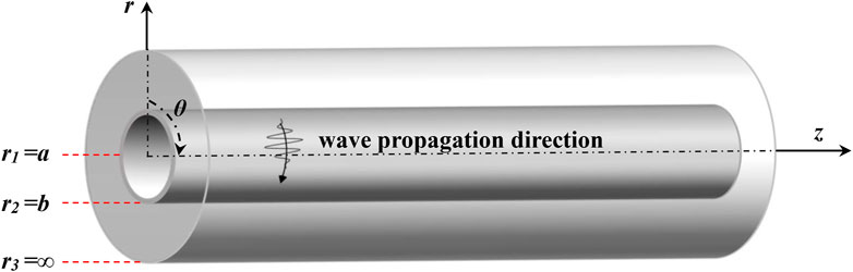
FIGURE 1. The geometry of a semi-infinite coated hollow circular tube in cylindrical coordinate system.
The intrinsic structure relationship for orthotropic isotropic materials in the column coordinate system is:
In the small deformation hypothesis, the geometric relationship of the structure in the column coordinate system is:
In Eqs 1, 2, ui, σij and εij represent the displacement, stress and strain, respectively; Cij is the elastic constant of the medium.
The equation of motion in the column coordinate system under the condition without body force is:
To transform the basic equations for elastic waves into a state matrix, the displacement and stress field quantities mentioned above must be expressed in vector form. As circumferential SH waves propagate in the circumferential direction, the harmonic factor is defined as ei(kθ-ωt), and the displacements and stresses are reformulated as state vectors in the following manner:
In Eq. 4, k is the wave number and ω is the angular frequency.
By utilizing the state vector format, the equations of motion can be expressed in terms of the stress and displacement vectors, which are derived as follows:
Where the expression for M is
The matrix form of the stress vector can be obtained by combining the intrinsic and geometric equations, expressed as follows:
Where the [Dij] is the matrix of elastic constants, and more information about it can be found in the Appendix.
By combining Eqs 5–9, the dispersion equation for the state vector can be obtained as follows:
The derivation of Eq. 10 is discussed in detail in the literature (Gao et al., 2019).
In order to solve the above dispersion characteristic equations, the displacement of the circumferential wave is expanded using the Legendre polynomial and Laguerre polynomial, Legendre series expansion for the displacement in the steel pipe and Laguerre series expansion for the displacement in the cement. As the circumferential SH wave only vibrates along the z-direction, only the z-directional displacement component needs to be expanded.
The displacement component in the steel matrix can be expressed as:
Where Qn (χ) is the Legendre polynomials of order n over χ ϵ [−1,1], ψn is the Legendre polynomials expansion factor, N is the cut-off order of the Legendre polynomials, and s represents the displacement in the steel matrix. Since the interval of the Legendre polynomials is [−1,1], the coordinates r (a ≤ r ≤ b) need to be transformed to the coordinates χ and further deduced as follows:
Substituting Eqs 11, 13 into Eq. 10, multiplying both sides of the equation by Legendre polynomials of order M and then integrating χ from −1 to 1 yield.
Using the recurrence relation of the Legendre polynomials,
The displacement component in the cement cladding can be expressed as:
Where Ln(χ) is the Laguerre polynomials of order n over χ ϵ [0, +∞], Fn is the Laguerre polynomials expansion factor, N is the cut-off order of the Laguerre polynomials and c represents the displacement in the cement cladding. Since the interval of Laguerre polynomials is [0, +∞], the coordinates r (r ≥ b) need to be transformed to the coordinates χ, and further calculations are performed as follows:
Substituting Eqs. 16, 18 into equation Eq. 10, multiplying both sides of the equation by Laguerre polynomials of order m, and integrating over χ from 0 to +∞, the result obtained is:
Using the recurrence relation for Laguerre polynomials,
In addition, in order to solve for circumferential SH waves in the cementing structures of cementing casing, the inner surface should satisfy stress-free boundary conditions, and the interface between steel and cement layers should satisfy stress and displacement continuity conditions, the boundary conditions under the state vector as well as the continuity conditions can be expressed as:
Combining Eqs 14, 19, and Eqs 21–23, the linear characteristic equation can be obtained as:
Where R, S, T is the corresponding coefficient matrix, and Ω is the Legendre and Laguerre polynomials coefficient matrix. To simplify the calculation, the unit matrix I and the auxiliary variable Λ = ikRΩ are introduced, transforming Eq. 24 into the linear characteristic problem:
Ultimately by solving for the eigenvalues of Eq. 25, the wave number k can be obtained, and the dispersion curve of the circumferential SH wave can be calculated.
2.2 Validation
The steel pipe was calculated with an inner radius a of 80 mm, an outer radius b of 90 mm, and the mechanical property parameters of the steel pipe and cement are presented in Table 1. In order to improve the convergence of higher-order modes in the dispersion curve, the order N of the series cut-off term is set to 10.

TABLE 1. Mechanical property parameters of cementing casing material.
Figure 2 shows a comparison between the phase velocity dispersion curves obtained in this research and the results reported in the literature (Paweł, 2017). The latter used a combination of semi-analytical finite elements and fully matched layer techniques to analyze the propagation characteristics of circumferential waves, and the mechanical property parameters and geometric parameters of the materials used in this research are consistent with this method. This demonstrates that the method employed in this research is suitable for evaluating the propagation characteristics of circumferential SH waves in the cementing casing, which verifies the accuracy of the method. In addition, the method uses the recursive and orthogonal properties of the Legendre and Laguerre polynomials to derive analytical solutions to integral expressions, avoiding large-scale integration operations and reducing matrix construction time.

FIGURE 2. Dispersion curves of circumferential SH waves in cementing casing.
The dispersion curve shows that the velocity of each mode tends to be the same as the frequency increases, with the circumferential SH0 mode being nearly a straight line over the whole frequency range, indicating that the dispersion of this mode is weak, so the circumferential SH0 mode is chosen for the numerical simulation of cement bonding defects in the cementing casing.
3 Simulation of casing cement bonding defects
3.1 Simulation model
A three-dimensional simulation model of the cementing casing was established for finite element analysis with the help of the finite element software ABAQUS, as shown in Figure 3.
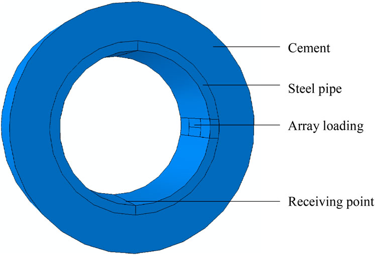
FIGURE 3. 3D finite element simulation model of cementing casing.
The simulation area consists of a steel pipe and cement cladding, which are rigidly connected. The thickness of the cement cladding is considered semi-infinite in the theoretical calculation. However, because of the actual situation and the calculation efficiency, the thickness of the cement cladding is set to 40 mm in the model. The loading area consists of two rectangles of 40 mm in length and 10 mm in width. The excitation signal of the same size and opposite direction is applied to both areas simultaneously along the z-direction only, as shown in Figure 4. The receiving point is set at the inner wall of the casing, in the same plane as the center of the loading area, and the arc length between the two points is 1/4 of the circumference of the inner diameter of the pipe.
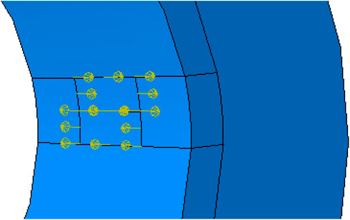
FIGURE 4. Schematic of incentive loading.
This research investigates the effect of the cementitious defect’s radial depth and circumferential angle on the circumferential SH wave, setting the defect in the area between the loading position and the reception point using the part function module in the software. Both defects run the entire length of the cement cladding in the z-direction, so the axial depth is set at 100 mm. Firstly, the circumferential angle of the defect is fixed at 15°, and the radial depth is set in steps of 10 mm, increasing from 10 mm to 40 mm; secondly, the radial depth of the defect is fixed at 10 mm and the circumferential angle is set in steps of 15°, increasing from 15° to 60°. A schematic diagram of the two defects is shown in Figure 5.
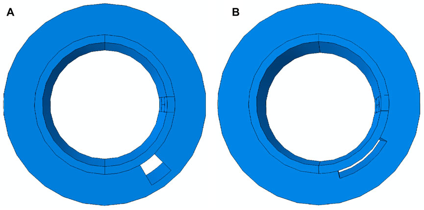
FIGURE 5. Diagram of cement bonding defects. (A) Radial depth defect. (B) Circumferential angle defect.
3.2 Parameter setting for the excitation
Considering the relationship between casing thickness and wavelength, as well as between frequency and detection sensitivity, the modal wavelength of SH0 was selected as 20 mm, twice the wall thickness. Thus, combined with the theoretical derivation of the SH wave dispersion curve, the frequency of the waveguide can be determined as 159 kHz. The excitation signal is a sinusoidal signal modulated by a five-period Hanning window.
Where n is the pulse period; f is the center frequency; τ is the signal pulse width; and τ = n/f. The waveform is shown in Figure 6.
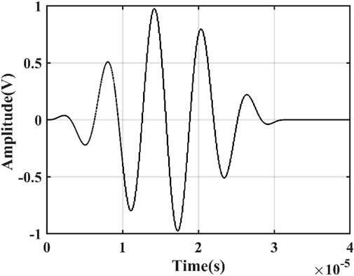
FIGURE 6. Excitation signal waveform diagram.
3.3 Mesh principles
The simulation uses a dynamic display solver, and the solution time step should be less than 1/8 of the period, setting the time step to 0.1 μs and the total solution time to 200 µs In addition, the mesh should be as fine as possible when meshing to ensure that the wave propagation process can be accurately modeled. However, a perfect mesh size will dramatically increase the number of cells and affect computational efficiency. Therefore, it is essential to have a suitable mesh division for the model.
According to the wave transmission effect, the maximum mesh size must satisfy the following conditions.
In Eq. 27: λmin is the minimum wavelength corresponding to the excitation of the generated modal wave; Δx, Δy, and Δz are the spacing between two adjacent nodes in the x, y, and z directions, respectively. Taking into account the accuracy of the calculation results and the speed of the calculation, the mesh cell length is chosen as 1 mm and the cell type is the eight-node linear hexahedral cell C3D8R, as shown in Figure 7.
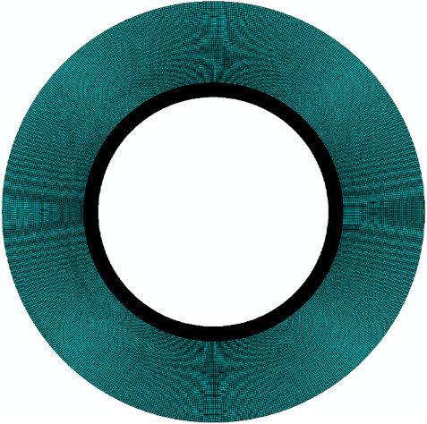
FIGURE 7. Meshing of cementing casing model.
4 Interaction of cement bonding defects with circumferential SH waves
4.1 Signal verification
The model is set up in finite element simulation software ABAQUS as described above, and simulations are carried out. As the circumferential SH guide wave only vibrates in the z-direction and propagates in the θ-direction, only the displacement in the z-direction at the receiving point needs to be extracted. To verify the correctness of the proposed model and determine whether circumferential SH waves can be excited, the radial depth and circumferential angle of the bonding defect are first set to 0 to simulate an excellent gluing condition. Then the displacement signal at the receiving point is extracted, and the wave speed is calculated according to the crossing time and compared with the theoretical calculation.
When the casing is effectively cemented, the signal obtained is shown in Figure 8, where the first wave packet represents the initial excitation signal of the loading area, the second wave packet indicates the displacement signal at the receiving point, and the transition time between the peaks of the two wave packets is 38.7 µs The spacing between the two packets is 1/4 of the circumference of the inner diameter of the steel pipe, from which the guided wave speed can be calculated as 3247 m/s. The speed of the dispersion curve in the theoretical calculation is 3194 m/s coincides. This indicates that the model developed above produces a circumferential SH0 guided wave, and also lays the foundation for subsequent investigation of the interaction between the bonding defects and the circumferential SH wave.
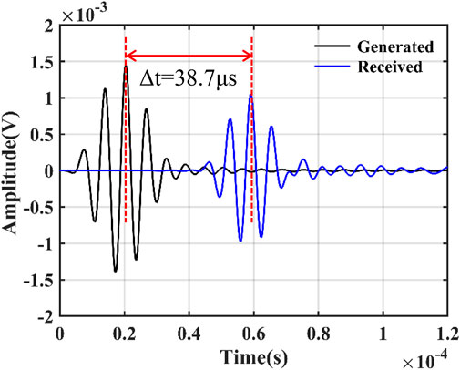
FIGURE 8. z-directional displacement of the receiving point in intact cementation.
4.2 Relationship between radial depth and signal attenuation
The displacement signal obtained by changing the radial depth when cement bonding defects occur is shown in Figure 9. The four wave packets in the figure basically coincide, and the transition time of the four wave packets does not change significantly compared with the wave packets in intact cementation, which indicates that the change of the radial depth of the defect does not affect the circumferential SH0 wave velocity. In order to explore the interaction between radial depth of the defect and circumferential SH wave amplitude, the wave packet amplitudes at radial depths of 10 mm, 20 mm, 30 mm, and 40 mm are extracted and fitted, respectively. The resulting variation pattern is shown in Figure 10.
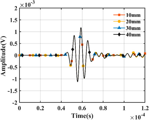
FIGURE 9. Simulation results of cement bonding defects at different radial depths.
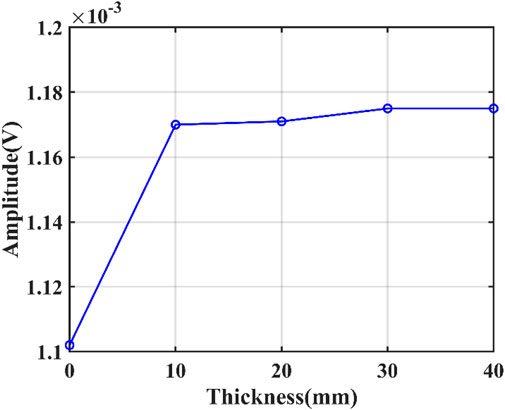
FIGURE 10. Radial depth variation pattern of cement bonding defects.
Comparing the peak value of the wave packet at the reception point when the cementation is intact, it can be seen that the amplitude of the direct wave is significantly higher. This is because the circumferential SH0 wave propagates in the circumferential direction of the casing and also diffuses energy into the cement cladding. However, when cement bonding defects exist between the cement and the casing, the circumferential SH0 wave no longer diffuses energy into the defects. The direct wave energy increases, and the amplitude becomes larger. As the radial depth increases, the change in direct wave amplitude is no longer significant, suggesting that the attenuation of circumferential SH0 waves by cement bonding defects is independent of the missing volume of cement.
4.3 Relationship between circumferential angle and signal attenuation
The simulation results for different circumferential angles are shown in Figure 11. Consistent with the simulation results obtained by changing the radial depth, the transition time of the four wave packets does not change, indicating that the wave velocity of the circumferential SH0 wave is not affected by the circumferential angle of the defect. However, it is clear from the local magnification that the amplitude of the direct wave increases as the angle increases. In order to visualize the interaction between the circumferential angle of the defect and the circumferential SH wave, the direct wave amplitudes corresponding to the four angles were fitted, and the results are shown in Figure 12. The attenuation of the circumferential SH waves is related to the missing surface area of the cement.

FIGURE 11. (A) Simulation results of cement bonding defects at different circumferential angles. (B) Partial enlarged view.
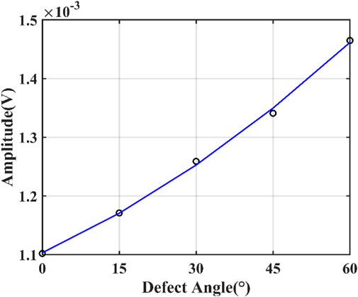
FIGURE 12. Circumferential angle variation pattern of cement bonding defects.
5 Conclusion
This research solves the circumferential SH wave propagation characteristics of a semi-infinite domain cladding hollow circular pipe, based on the state matrix method and the joint level expansion of Legendre and Laguerre polynomials. The feasibility and accuracy of the proposed theoretical approach is verified by comparing the results with those of the existing literature. In addition, a finite element simulation model of the cementing casing structure is established, and the model’s accuracy is verified by comparing the simulation results with the theoretical calculation results. The interaction between different types of cement bonding defects and the circumferential SH wave is investigated. The results show that the wave velocity of circumferential SH wave does not change due to the presence or size of the cement bonding defect, but its amplitude increases with the increase of the circumferential angle of the defect. Therefore, circumferential SH wave can be used to detect the surface area of cement bonding defects in the cementing casing. The quantitative characterization of cement bonding defects in the cementing casing will continue to be investigated in depth.
Data availability statement
The original contributions presented in the study are included in the article/Supplementary Material, further inquiries can be directed to the corresponding author.
Author contributions
The research was raised by RG, YL, and other co-authors. And the research work was also conducted by RG and YL, who played a major part in the development of the method mentioned in this manuscript. RG and YL carried out the theoretical derivation, and together with the main writing of this manuscript. GS, JG, and CH joined the discussion for the development of the method, and offered some useful proposals.
Funding
This work is supported by the National Natural Science Foundation of China (No. 12172016).
Conflict of interest
The authors declare that the research was conducted in the absence of any commercial or financial relationships that could be construed as a potential conflict of interest.
Publisher’s note
All claims expressed in this article are solely those of the authors and do not necessarily represent those of their affiliated organizations, or those of the publisher, the editors and the reviewers. Any product that may be evaluated in this article, or claim that may be made by its manufacturer, is not guaranteed or endorsed by the publisher.
References
Chen, X, L., and Tang, X. M. (2020). Propagation characteristics of quasi-SH waves propagating circumferentially in a casing. Acta Pet. Sin. 41, 865–902. doi:10.7623/syxb202007011
Chen, X. L., Zhuang, Y., Xia, F. Y., Yin, X. K., and Tang, X. M. (2022). Finite element simulation and experiment study on exciting quasi-SH wave circumferentially in the casing. Geophys 65, 1513–1527. doi:10.6038/cjg2022P0257
Froelich, B., Dumont, A., Pittman, D., and Seeman, B. (1982). Cement evaluation tool: A new approach to cement evaluation. JPT 34, 1835–1841. doi:10.2118/10207-pa
Gao, J., Lyu, Y., Zheng, M. F., Liu, M. K., Liu, H. Y., Wu, B., et al. (2019). Modeling guided wave propagation in functionally graded plates by state-vector formalism and the Legendre polynomial method. Ultrasonics 99, 105953. doi:10.1016/j.ultras.2019.105953
Kuijk, R. V., Zeroug, S., Froelich, B., Allouche, M., Bose, S., Miller, D., et al. (2005). “A novel ultrasonic cased-hole imager for enhanced cement evaluation,” in Paper presented at the International Petroleum Technology Conference, Doha, Qatar, November 2005. doi:10.2523/10546-MS
Pardue, G. H., and Morris, R. L. (1963). Cement bond log-A study of cement and casing variables. JPT 15, 545–555. doi:10.2118/453-PA
Patterson, D., Dighe, S., Matuszyk, P. J., Holley, A., and Wei, H. (2016). “Extending the understanding of in-situ cement properties,” in Abstract retrieved from Abstracts in SPWLA 57th Annual Logging Symposium, Reykjavik, Iceland, June 2016. Accession No. 20183405715689).
Patterson, D., Matuszyk, P. J., and Bolshakov, A. (2015). Utilization of electromagnetic acoustic transducers in downhole cement evaluation. Petrophysics 56, 479–492.
Paweł, J. M. (2017). Modeling of guided circumferential SH and Lamb-type waves in open waveguides with semi-analytical finite element and Perfectly Matched Layer method. JSV 386, 295–310. doi:10.1016/j.jsv.2016.09.019
Song, R. L., Liu, J. X., Hou, C. H., and Wang, K. X. (2012). Numerical simulation of Sector Bond log and improved cement bond image. Geophysics 77, 95–104. doi:10.1190/geo2011-0273.1
Tang, J., Zhang, C. G., Zhang, B. X., and Shi, F. F. (2016). Cement bond quality evaluation based on acoustic variable density logging. PED 43, 514–521. doi:10.1016/S1876-3804(16)30060-X
Tang, X. M., Bolshakov, A., and Domangue, E. (2010). Cement bond analysis. U.S. Patent No. 7,787,327.
Tang, X. M., Bolshakov, A., Wang, T., and Patterson, D. (2005). Method and apparatus for cement bond evaluation using transversely polarized shear waves. U.S. Patent No. 20,050,190,648.
Tang, X. M., Bolshakov, A., Wang, T., and Patterson, D. (2009). Method and apparatus for cement bond evaluation using transversely polarized shear waves. U.S. Patent No. 7,525,872.
Wang, A. M. (2003). Sector cement bond tool and its applications in the cased holes. WLT 27, 56–58. doi:10.16489/j.issn.1004-1338.2003.sl.017
Wang, H., Guo, T., and Shang, X. F. (2016). Understanding acoustic methods for cement bond logging. JASA 139, 2407–2416. doi:10.1121/1.4947511
Yu, J. G., and Dong, X. F. (2008). Circumferential SH waves in functionally graded hollow cylinders. SPAWA 2008, 328–332. doi:10.1109/SPAWDA.2008.4775802
Zhao, X. L., and Rose, J. L. (2004). Guided circumferential shear horizontal waves in an isotropic hollow cylinder. JASA 115, 1912–1916. doi:10.1121/1.1691037
Zheng, M. F., He, C. F., Lyu, Y., and Wu, B. (2018). Guided waves propagation in anisotropic hollow cylinders by Legendre polynomial solution based on state-vector formalism. Compos. Struct. 207, 645–657. doi:10.1016/j.compstruct.2018.09.042
Appendix
Citation: Gong R, Lyu Y, Song G, Gao J and He C (2023) Finite element simulation of bonding defects in cementing casing based on circumferential SH guided waves. Front. Mater. 10:1195152. doi: 10.3389/fmats.2023.1195152
Received: 28 March 2023; Accepted: 07 April 2023;
Published: 21 April 2023.
Edited by:
Shifeng Guo, Shenzhen Institute of Advanced Technology (CAS), ChinaReviewed by:
Guoshuang Shui, Beijing Jiaotong University, ChinaXuan Peter Zhu, The University of Utah, United States
Yunze He, Hunan University, China
Copyright © 2023 Gong, Lyu, Song, Gao and He. This is an open-access article distributed under the terms of the Creative Commons Attribution License (CC BY). The use, distribution or reproduction in other forums is permitted, provided the original author(s) and the copyright owner(s) are credited and that the original publication in this journal is cited, in accordance with accepted academic practice. No use, distribution or reproduction is permitted which does not comply with these terms.
*Correspondence: Yan Lyu, bHZ5YW5AYmp1dC5lZHUuY24=