 Mei Zhang
 Long Li1
- 1Chongqing Chemical Industry Vocational College, Chongqing, China
- 2Shanghai Micropowers Co., Ltd., Shanghai, China
Fatigue failure, as the main failure form of aero-engine blades, has a direct impact on the reliability and service life of aviation equipment. In order to improve the service performance of machined blades, it is necessary to understand the failure process and failure mechanism of blades and then optimize the grinding process. This paper takes abrasive belt grinding of an 1Cr17Ni2 stainless steel blade as the research object and analyzes the fatigue failure mechanism by characterizing the surface morphology, cross-sectional microstructure, and cross-sectional characteristics of the fatigue failure blade. The results show that cracks are prone to propagate in carbon-rich areas with poor mechanical properties inside the material, and the accumulation of large-size carbon-rich areas leads to continuous cracks easily and accelerates crack growth. The grinding process promotes the migration and consumption of surface carbon elements and forms a carbon consumption layer on the surface of the material, which can inhibit the initiation of fatigue cracks. The point-like pits on the ground surface have an adverse effect on the fatigue life and play a role in the initiation of fatigue crack enhancement. The direction of material research and development to homogenize the structure of the material and the direction of anti-fatigue grinding to increase the thickness of the carbon consumption layer on the ground surface and avoid the damage of micro-pits are proposed. The research has important guiding significance for anti-fatigue machining of key components.
1 Introduction
Fatigue failure, as an important failure form of an aircraft, is also called “The Butterfly Effect” in the aviation field because the early crack initiation and propagation are difficult to detect, and the later fatigue fracture is harmful (Huang et al., 2021a). Aviation accidents caused by fatigue failures have occurred often in recent years. For example, on 17 April 2018, the accident resulting in the death of a passenger was caused by a Southwest Airlines passenger plane crash-landed at Philadelphia International Airport. On 20 February 2021, the right engine of a Boeing 777–200 passenger plane of United Airlines exploded and burned violently. After, the National Transportation Safety Board (NTSB) investigated the role of metal fatigue and crack growth in both crashes. Therefore, the fatigue failure is very important for the safe and reliable operation of aviation aircraft and the safety of human life. Bhaumik et al. (2008) pointed out that about 60% of in-service aviation component failures were caused by fatigue failure. Meanwhile, the cost of testing and maintenance is as high as billions of dollars due to fatigue failure each year (Yang, 2015).
Aero-engine blade, as a typical rotating component of aero-engine, is extremely harmful to fatigue failure due to its high rotational speed (up to 15,000 RPM/min) and large centrifugal force. The aero-engine blades are always subjected to loads with different frequencies and amplitudes due to the change of the running state, which causes fatigue failure (Yue et al., 2020). According to statistics, the fatigue failure of aero-engine blades accounts for more than 80% of engine failures. It is necessary to increase the service life of an aero-engine in a harsh service environment, so the fatigue resistance of mechanical parts such as aero-engine blades has become an important evaluation index of aero-engine safety performance (Jiang et al., 2020; Ludwig et al., 2020; Zhao et al., 2020). 1Cr17Ni2 stainless steel is a strong combination of low-carbon chromium nickel steel, which has a series of excellent features such as high strength, high hardness, and good corrosion resistance. Therefore, it is used in the production of key mechanical components requiring both strength toughness and corrosion resistance. It is currently mainly used in the production of first-stage compressor rotor blades for turbojet engines in the field of aviation industry (Sun et al., 2009; Li et al., 2020; Li et al., 2020). The improvement of the service life is limited by the fatigue. In order to improve its fatigue life, it is necessary to optimize the research and development of materials and optimize the manufacturing process (Li et al., 2023).
Grinding technology, as the final material removal process of aero-engine blades, is widely used in the finishing of aero-engine blades (Xiao et al., 2021). Especially, abrasive belt grinding is widely used because it has the functions of grinding and polishing, and the grinding temperature is also low. However, the surface state and fatigue life are affected by the grinding process. At present, the excellent anti-fatigue resistance is mainly analyzed through the comparison of various processes (Li et al., 2022a). However, the cycle is long, and the cost is high due to the lack of pertinence in process exploration. At the same time, the research on the anti-fatigue resistance of aero-engine blades mostly focuses on the macroscopic evaluation indexes such as surface roughness (Wang et al., 2019; Liang et al., 2020; Martín et al., 2020), residual stress (He et al., 2018; Ramakokovhu et al., 2021), and microstructure (Sen et al., 2021) at present. However, the interaction among the aforementioned factors is complex, and it is difficult to realize decoupling, which makes the development of materials and the formulation of the anti-fatigue manufacturing process lack pertinence. In addition, the initiation and propagation of fatigue cracks are highly localized (Menapac et al., 2022), and the macroscopic evaluation index of surface integrity has limitations, which makes it difficult to accurately predict the fatigue failure process. The failure process and mechanism analysis of aero-engine blades can provide guidance for the formulation of anti-fatigue manufacturing technology.
The research on the fatigue failure mechanism and process of grinding blades is the basis of anti-fatigue manufacturing (Wang et al., 2021; Li et al., 2022b). In order to explore the fatigue failure mechanism of abrasive belt grinding blades and then provide a theoretical basis for anti-fatigue grinding, a 1Cr17Ni2 stainless steel blade was taken as the research object in the paper, and its surface morphology and cross-sectional microstructure and fracture morphology were characterized and analyzed in the grinding process, so its fatigue failure mechanism was revealed. The requirements of anti-fatigue resistance of blades were analyzed in reverse through the analysis of the fatigue failure mechanism of grinding the aero-engine blade, and then, the specific guidance was provided for material development and anti-fatigue process formulation.
2 Materials and methods
2.1 Materials
The object of this paper is 1Cr17Ni2 stainless steel grinding by using an abrasive belt, and its geometric structure is shown in Figure 1. It is mainly composed of a tenon and a blade body, and the blade body is composed of a suction surface and a compression surface; also, they are two typical complex surfaces. The chemical composition mass ratio and mechanical properties of the samples are shown in Table 1 and Table 2, respectively. The blades were processed from forged blanks by reduced materials. The blank was first milled to ensure the accuracy of the profile followed by precision grinding to obtain a smooth surface. The full blade surface was ground by using a seven-axis and six-linkage belt grinder under a constant force.
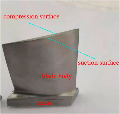
FIGURE 1. Aero-engine blade sample.

TABLE 1. Element weight percentage of the 1Cr17Ni2 stainless steel blade sample.
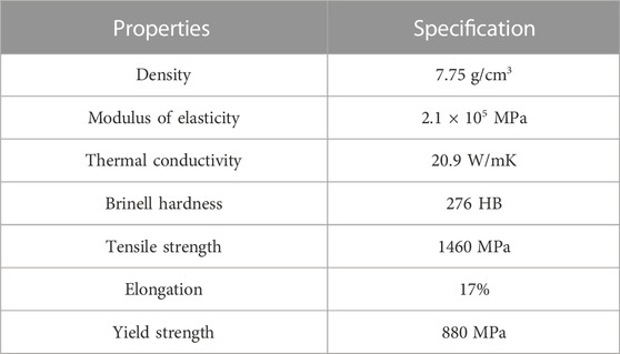
TABLE 2. Mechanical properties of 1Cr17Ni2 at room temperature.
2.2 Methods
During the service of aero-engine blades, they are always subjected to loads with different frequencies and amplitudes due to the change of the running state of the aircraft, and the first-order resonance frequency is the most harmful to the blade (Huang et al., 2021b). So, the vibration fatigue test is carried out at the first-order resonance frequency. The fatigue test was carried out by using the electromagnetic excitation vibration platform. The vibration fatigue test is shown in Figure 2. As shown in Figure 2, the blade is fixed in the special clamp, then the clamp is fixed on the vibration fatigue test platform, and the piezoelectric frequency sensor is fixed at the dangerous part of the blade. First, the vibration frequency of the blade is obtained from the mechanism response when the sweep frequency is within the range of 5–2000 Hz. The natural frequency of the blade is determined to be 1783 Hz. Then, the vibration fatigue test is carried out at this frequency, and the fatigue test load is 650 MPa. The number of fatigue cycles (i.e., fatigue cycle life) of the blades was recorded during the process.
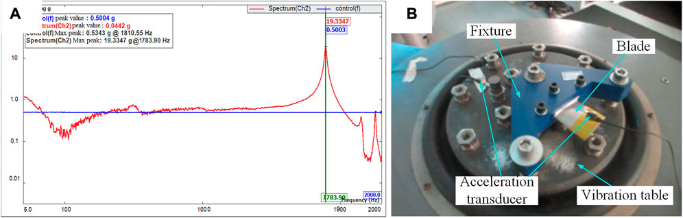
FIGURE 2. (A) Sweep frequency response curve and (B) schematic diagram of vibration fatigue.
Simultaneously, in order to have a more comprehensive understanding of the blade fatigue failure process, the initiation and propagation of fatigue cracks are recorded by the surface of the blade, cross section of the blade, and cross-sectional morphology of the blade, and the fatigue failure mechanism of the grinding aero-engine blade is analyzed by the aforementioned characteristics in this paper. The surface morphology of the fatigue failure blade crack initiation site is observed by using an SEM, and the model of the SEM is Quattro S. The back root is the dangerous part of the blade, its microscopic structure is observed by SEM and metallographic microscope after wire cutting and polishing and chemical corrosion, and the model of the metallographic microscope is DM 2000X. The characteristics of the blade section were observed by ultra-depth microscope after vibration fatigue fracture, the model of the ultra-depth microscope is VHX-1000C/VW-6000. At the same time, the failure blade was cut along the direction of the vertical fatigue crack, and the change of metallographic structure was observed, and the distribution of chemical elements was analyzed near the crack after mechanical polishing and chemical etching. The element distribution of the material was obtained by EDS.
3 Results and discussion
3.1 Surface characteristics of the fatigue source
The surface morphology of the fatigue blade is shown in Figure 3. It can be seen from Figure 3A that blade fatigue cracks appear at the back of the blade near the root of the blade and extend along the direction perpendicular to the body of the blade. This is consistent with the direction of load on the blade surface, indicating that the direction of the load is the main factor affecting the direction of crack propagation. It can be seen from Figure 3B that approximately circular micro-pits are also found at the blade fatigue source in addition to grinding marks. It can be seen from Figure 3C that there are a large number of micro-pits near the crack, and some of them cross during the process of crack growth. This phenomenon indicates that the micro-pit has an important effect on the initiation and propagation of cracks. In order to obtain the basic information of surface micro-pits, the cross-sectional information of micro-pits is obtained by wire cutting and polishing. The cross-sectional microstructure diagram of the micro-pit is shown in Figure 3D, and it can be seen that the size of the micro-pit is about 50 μm. In addition, the grain size at the bottom of the micro-pit is larger than that at the surface of the micro-pit.
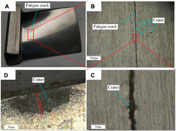
FIGURE 3. Surface morphology of the fatigue blade. (A) Macro-cracks on the surface of the blade, (B) surface morphology near the crack source, (C) dimples on the crack, and (D) cross-sectional view of the dimples.
3.2 Section microstructure
The blade cross-sectional microstructure is shown in Figure 4. Figure 4A is a picture of the crack section. It can be seen that the crack growth is characterized by extreme depth propagation. In other words, the crack depth is much larger than the crack width, and the crack growth direction is approximately perpendicular to the grinding surface, so this type of fatigue failure has an extremely adverse effect on the service reliability of the aero-engine blade. The grinding surface microstructure is shown in Figure 4B. The grinding surface is white, which is more uniform and diffuses along the depth direction, and the area decreases gradually, while the microstructure of the core is dark. At the same time, the color change of the blade surface material has a gradual gradient. This phenomenon indicates that the composition and properties of the surface materials of the blade are changed due to grinding, and this change is extended from the surface to the inside. The crack tip is shown in Figure 4C. It can be seen that the crack growth shows an intergranular propagation. This indicates that cracks are more likely to propagate at grain boundaries. The metallographic structure of the grinding surface is shown in Figure 4D. It can be seen that the grain size is small on the grinding surface, while the grain size is larger near the core. Due to the refinement of surface grains, the number of grain boundaries increases, and the number of grain boundary barriers encountered in the process of crack propagation increases, so the crack propagation resistance increases, which is not conducive to crack propagation and the formation of large fatigue cracks. In addition, it can also be seen from Figure 4D that the gradient color characteristics of the blade surface are consistent with the observation results of the microstructure in Figure 4B. This indicates that microstructure refinement is a possible factor for the color variation of surface materials. That is, the surface grain refinement leads to the change of material properties.
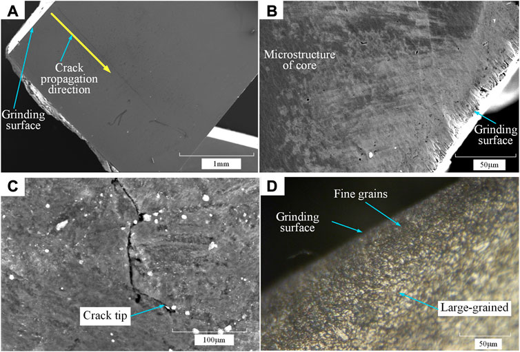
FIGURE 4. Blade cross-sectional microstructure. (A) Crack section, (B) grinding surface microstructure, (C) crack tip, and (D) grinding surface metallography.
Through the aforementioned analysis, we know that the grain refinement occurs on the grinding surface of the material, but the changes of the material elements and phases will affect the state and performance of the material (Qin et al., 2021). In order to further obtain the reasons for the changes in the surface microstructure, the element distribution of the grinding surface and core structure are analyzed by EDS. The element distribution on the ground surface is shown in Figure 5. It can be seen that the carbon elements, potassium elements, and sulfur elements have great changes on the grinding surface, among which the carbon content changes the most, the carbon content of the surface tissue is 64% lower than that of the core tissue, and it indicates that the carbon content of the surface material is consumed during grinding. However, there was a 30% increase in sulfur element. As we all know, the increase of potassium and sulfur content in steel makes the grinding surface brittle, which has an adverse effect on the initiation of fatigue cracks (Maciejewski, 2015).
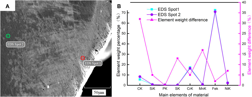
FIGURE 5. Element distribution on the ground surface. (A) Schematic diagram of detection points. (B) Element content comparison.
3.3 Fatigue section characteristics
The processes of fatigue crack initiation and propagation are recorded by the fatigue section, and the section morphology of the fatigue fracture blade is shown in Figure 6. It can be confirmed from Figure 6A that the fatigue cracks start from the middle of the blade back near the blade root and then radiate to the inside of the blade. At the initial stage of crack growth, the crack propagates in both the depth direction and the vertical blade body, and the propagation speed in the depth direction is slightly slower than that in the vertical blade body direction. As the crack propagates along the depth direction near the blade basin, the crack growth slows down along the depth direction, and the crack growth rate along the width direction is greater than that along the depth direction. When the crack depth direction extended to the side of the blade, the crack depth direction is stagnant, and only the crack growth speed is found in the vertical blade body direction. The morphological characteristics of the blade fracture surface are shown in Figure 6B, and a bright area with metallic tint and a dark area are discovered on the fracture surface. There are micro-cracks in the dark area, and the micro-cracks are connected with each other and even form continuous cracks in the continuous area. This also indirectly confirms that the grinding process has an effect on the properties of the surface materials, which corresponds to the microstructure results in Section 3.1. Figure 6C is an enlarged figure; it can be seen that the size of micro-cracks is large and the number of micro-cracks is high in the dark area, while the number is low and the size is small in the surrounding matrix; it indicates that the strength is poor and cracks easily initiate in the dark area. It is known from Section 3.1 that the grinding surface has dark areas, which also indicates that the grinding process leads to partial degradation of the material properties, which, in turn, makes it more prone to crack initiation.
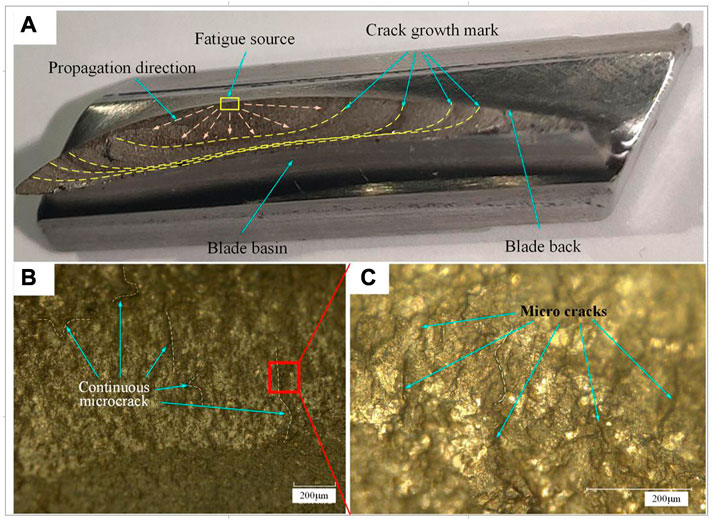
FIGURE 6. Section morphology of the fatigue fracture blade. (A) Overall characteristics of the section, (B) partial morphology of the section, and (C) micro-cracks on the section.
The elements and composition of the material directly affect the mechanical properties of the material and, thus, the bearing capacity of the surfaces (Gholami-Kermanshahi et al., 2023). In order to deeply understand the formation mechanism of the crack, the microstructure of the crack section is analyzed by EDS, and the distribution of elements is obtained near the crack, as is shown in Figure 7. It can be seen that the content of C element is high near the crack, the content of Fe element is low, and the distribution of other elements has little difference; it is indicated that the crack growth is related to the uneven distribution of the C element. This conclusion is consistent with the aforementioned analysis results and also proves that the difference of element distribution is the main reason for the difference of material properties on the grinding surface.
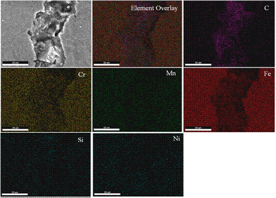
FIGURE 7. Element distribution near the fatigue crack.
3.4 Fatigue section characteristics
It can be seen from the surface characteristics of the fatigue failure blade that the propagation direction of the fatigue crack is perpendicular to the direction of the blade, and it is parallel to the direction of the grinding marks, which is consistent with the direction of the load. In order to explore the impact of blade geometry on fatigue failure, a blade model was established and combined with the test parameters, and the fatigue life of the blade under the first-order vibration frequency was simulated in ANSYS. The simulation results of the fatigue life of the blade geometry model are shown in Figure 8; it can be seen that there is stress concentration at the root, and it has the shortest theoretical fatigue life. Also, the actual fracture part of the blade is located at a certain distance from the root. At the same time, the actual fatigue cycle number of the blade is 323,479, which is lower than the theoretical minimum fatigue cycle number of dangerous parts (448,880). Based on the analysis of the microstructure and fatigue failure process of the blade surface, it is considered that this is caused by the change of the texture characteristics and microstructure properties of the grinding surface. The actual fatigue position of the blade is observed under the microscope, and it is found that there are punctuate micro-pits on the surface and there are more micro-pits near the fatigue cracks, which indicated that the micro-pits play a role in promoting the initiation of fatigue cracks on the surface. It can also be seen from the case that the initiation of fatigue cracks is highly localized, so there are some limitations in using macroscopic roughness evaluation standard. That is, the evaluation parameter within the range of roughness cannot evaluate the influence of local pitting defects on fatigue life, and the evaluation method cannot take into account the influence of material microstructure and other influences on material properties.

FIGURE 8. Simulation results of the fatigue life of the blade geometry model.
The distribution of elements in a material affects its mechanical properties and, thus, its service performance after forming (Xie et al., 2017; Li S. C. et al., 2022; Li Z. F. et al., 2022). In order to explore the cause of the crack source, it is necessary to explore the distribution difference of elements and morphological characteristics near the crack source. The surface characteristics and element distribution of the blade are shown in Figure 9 and Table 3, respectively. An interesting phenomenon is found in the surface morphology of the blade. In other words, there are many micro-cracks in the black area of the section, and continuous micro-cracks also appear in the continuous part of the black area, which has an extremely adverse effect on the anti-fatigue resistance. However, the aforementioned cracks are not found in the surrounding matrix; it is indicated that the strength of the black area is weak, which is conducive to the initiation of fatigue cracks, and then, the large-diameter black particles play a role in promoting the propagation of fatigue cracks. The element content test results also showed that the carbon content in the black particle area is higher than that in the surrounding matrix. From the distribution of the elements in different regions (Figure 9; Table 3), it can be seen that the content of carbon increases from 5%–6% to 9%–10% of the matrix. The corresponding iron content dropped by about 2%, while the other elements remained roughly the same. It is indicated that the change of material properties was caused by the non-uniform distribution of carbon elements. Micro-cracks are easily generated in the area with large carbon content due to its hard and brittle characteristics, which promotes the initiation and propagation of cracks. Therefore, the uniformity and consistency of the material composition should be improved in the development stage of materials, so as to avoid the adverse effects of large particle size carbon-rich on the initiation and propagation of fatigue cracks. At the same time, the influence of surface thermodynamic coupling factors on material properties should be avoided in the process of blade molding.
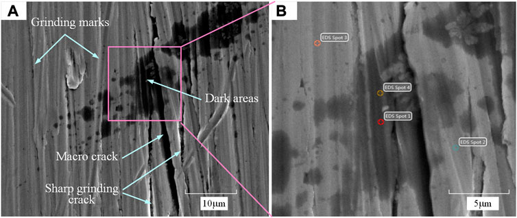
FIGURE 9. (A) Surface characteristics of the blade and (B) Schematic diagram of detection points.
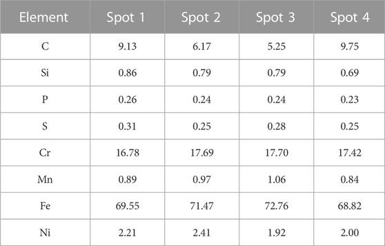
TABLE 3. Surface element distribution of the blade.
Fatigue cracks usually start at the surface (Kimmo et al., 2023). In this study, the grinding surface, as the machined surface, has a direct effect on the initiation of fatigue cracks. From the crack growth diagram, it can be seen that the fatigue crack originates from the grinding surface and then radially propagates to the inside of the material. The turning direction of crack growth appears about 400 mm below the surface layer; it is indicated that the property of the material has changed. There is a competitive mechanism between grain refinement and carbon content increase. The grain refinement inhibits crack propagation, while the carbon enrichment promotes crack formation and propagation. Combined with the surface microstructure and metallographic observation, it is concluded that the change of carbon content leads to the different direction of crack growth.
4 Conclusion
In order to understand the fatigue failure mechanism of abrasive belt grinding blades, which provides directions for material development and anti-fatigue surface grinding process development, the vibration fatigue tests are carried out on aero-engine blades after abrasive belt grinding, and the fatigue failure mechanism of blades is analyzed based on the surface morphology, section microstructure, and section characteristics in the paper. The following conclusions can be drawn from the paper:
1) The micro-pits have an adverse effect on the initiation of fatigue cracks on the grinding surface, and the micro-pits will promote the initiation of fatigue cracks, so it should be avoided as far as possible in the grinding process of aero-engine blades. In addition, it has also been shown that the use only surface roughness to evaluate the anti-fatigue resistance is limited because roughness cannot evaluate the influence of highly localized defects on fatigue life. In order to accurately evaluate the fatigue life of blades, it is necessary to establish a comprehensive evaluation method combining geometry, load properties, surface morphology, defect characteristics, and microstructure.
2) For stainless steel blades, the change of carbon content has a significant effect on material properties. The crack always appears with carbide inside the material due to the influence of stress concentration in the process of fatigue crack growth. This is because the accumulation of carbon elements will lead to the increase of brittleness and decrease of toughness of the material, which makes the initiation of fatigue cracks easier. So, the distribution of carbide should be controlled in abrasive belt grinding processes to avoid carbide aggregation, which is beneficial to delay the propagation of the fatigue crack in the process of material production.
3) There is a competitive mechanism between grain refinement and carbon content increase. The surface grain refinement increases the number of grain boundaries and, thus, delays crack propagation. The carbide easily causes fatigue crack initiation due to its low strength in the blades. The carbon consumption layer inhibits the initiation of fatigue cracks on the surface. That is to say, increasing grain refinement and carbon consumption can effectively improve the fatigue life. The surface material is refined by grinding heat and force load, and the carbon consumption layer is formed in the grinding process. So, it is necessary to increase the depth of the surface carbon consumption layer, and it is beneficial to improve the fatigue resistance during the abrasive belt grinding process.
Data availability statement
The original contributions presented in the study are included in the article/Supplementary Material; further inquiries can be directed to the corresponding author.
Author contributions
XY, DW, and MZ conceived and designed the study. MZ and LL performed the experiments. MZ wrote the manuscript. XY and DW reviewed and edited the manuscript. All authors read and approved the manuscript.
Conflict of interest
Author DW was employed by Shanghai Micropowers Co., Ltd.
The remaining authors declare that the research was conducted in the absence of any commercial or financial relationships that could be construed as a potential conflict of interest.
Publisher’s note
All claims expressed in this article are solely those of the authors and do not necessarily represent those of their affiliated organizations, or those of the publisher, the editors, and the reviewers. Any product that may be evaluated in this article, or claim that may be made by its manufacturer, is not guaranteed or endorsed by the publisher.
References
Bhaumik, S. K., Sujata, M., and Venkataswamy, M. A. (2008). Fatigue failure of aircraft components. Eng. Fail. Anal. 15 (6), 675–694. doi:10.1016/j.engfailanal.2007.10.001
Gholami-Kermanshahi, M., Wu, Y-Y., Lange, G., and Chang, S. H. (2023). Effect of alloying elements (Nb, Ag) on the damping performance of Cu–Al–Mn shape memory alloys. J. Alloys Compd. 930, 167438. doi:10.1016/j.jallcom.2022.167438
He, Y., Xiao, G-J., Li, W., and Huang, Y. (2018). Residual stress of a TC17 titanium alloy after belt grinding and its impact on the fatigue life. Mater. (Basel, Switz. 11, 2218. doi:10.3390/ma11112218
Huang, Y., Li, S-C., Xiao, G-J., Chen, B., He, Y., and Song, K. (2021b). Research on the fatigue failure behavior of 1Cr17Ni2 blades ground by abrasive belt with passivation treatment. Eng. Fail. Anal. 129, 105670. doi:10.1016/j.engfailanal.2021.105670
Huang, Y., Li, S-C., and Xiao, G-J. (2021a). Research progress of aero-engine blade materials and anti-fatigue grinding technology. J. Aeronautical Mater. 41, 17–35. doi:10.11868/j.issn.1005-5053.2021.000058
Jiang, R., Song, Y. D., and Reed, P. A. (2020). Fatigue crack growth mechanisms in powder metallurgy Ni-based superalloys-A review. Int. J. Fatigue 141, 105887. doi:10.1016/j.ijfatigue.2020.105887
Kimmo, K., Joona, V., Miikka, V., Niskanen, I., and Frondelius, T. (2023). The role of plasticity-induced crack closure in the non-propagation prediction of surface defect-initiated cracks near fatigue limit. Int. J. Fatigue 168, 107462. doi:10.1016/j.ijfatigue.2022.107462
Li, C., Piao, Y-C., Meng, B-B., Hu, Y., Li, L., and Zhang, F. (2022a). Phase transition and plastic deformation mechanisms induced by self-rotating grinding of GaN single crystals. Int. J. Mach. Tools Manuf. 172, 103827. doi:10.1016/j.ijmachtools.2021.103827
Li, C., Piao, Y-C., Zhang, F-H., Zhang, Y., Hu, Y., and Wang, Y. (2022b). Understand anisotropy dependence of damage evolution and material removal during nanoscratch of MgF 2 single crystals. Int. J. Extreme Manuf. 5, 015101. doi:10.1088/2631-7990/ac9eed
Li, L., Zhang, Q. X., and Zhu, B. (2020). Cause analysis of unqualified hardness of 14Cr17Ni2 stainless steel blade. Heat Treat. Metal 45 (07), 214–218. doi:10.13251/j.issn.0254-6051.2020.07.044
Li, S-C., Xiao, G-J., Chen, B-Q., Zhuo, X., Xu, J., and Huang, Y. (2022). Surface Formation modeling and surface integrity research of normal ultrasonic assisted flexible abrasive belt grinding. J. Manuf. Process. 80, 232–246. doi:10.1016/j.jmapro.2022.05.045
Li, S-C., Xiao, G-J., Zhuo, X-Q., Chen, B., Zhao, Z., and Huang, Y. (2023). Fatigue performance and failure mechanism of ultrasonic-assisted abrasive-belt-ground inconel 718. Int. J. Fatigue 168, 107406. doi:10.1016/j.ijfatigue.2022.107406
Li, Z-F., Gu, H., and Wu, G-Q. (2022). Effect of surface mechanical attrition on microstructure and mechanical properties of 1Cr17Ni7 stainless steel. Hot Work. Technol. 51 (22), 94–96. doi:10.14158/j.cnki.1001-3814.20201617
Li, Z-L., Xu, H., Shi, D-Q., Huang, J., Xu, G., and Yang, X. (2022). Combined tensile and bending fatigue behavior and failure mechanism of A blade-like specimen at elevated temperature. Int. J. Fatigue 164, 107163. doi:10.1016/j.ijfatigue.2022.107163
Liang, T., Yao, C-F., Zhang, D-H., Ren, J., Zhou, Z., and Zhang, J. (2020). Evolution of surface integrity and fatigue properties after milling, polishing, and shot peening of TC17 alloy blades. Int. J. Fatigue 136, 105630. doi:10.1016/j.ijfatigue.2020.105630
Ludwig, C., Rabold, F., Kuna, M., Schurig, M., and Schlums, H. (2020). Simulation of anisotropic crack growth behavior of nickel base alloys under thermomechanical fatigue. Eng. Fract. Mech. 224, 106800. doi:10.1016/j.engfracmech.2019.106800
Maciejewski, J. (2015). The effects of sulfide inclusions on mechanical properties and failures of steel components. J. Fail. Analysis Prev. 15, 169–178. doi:10.1007/s11668-015-9940-9
Martín, V., Vázquez, J., Navarro, C., and Dominguez, J. (2020). Effect of shot peening residual stresses and surface roughness on fretting fatigue strength of Al 7075-t651. Tribol. Int. 142, 106004. doi:10.1016/j.triboint.2019.106004
Menapac, C., Bernard, F., Lusa, M., and Straffelini, G. (2022). Optimization of the chemical composition of a commercial AA6060 alloy to maximize extrudability and mechanical properties. J. Mater. Res. Technol. 19, 2247–2256. doi:10.1016/j.jmrt.2022.06.014
Qin, G., Chen, R-R., Mao, H-H., Yan, Y., Li, X., Schonecker, S., et al. (2021). Experimental and theoretical investigations on the phase stability and mechanical properties of Cr7Mn25Co9Ni23Cu36 high-entropy alloy. Acta Mater. 208, 116763. doi:10.1016/j.actamat.2021.116763
Ramakokovhu, U., Desai, D., Snedden, G., and Jamiru, T. (2021). Significance of residual stresses in fatigue life prediction of micro gas turbine blades. Eng. Fail. Anal. 120, 105092. doi:10.1016/j.engfailanal.2020.105092
Sen, M., Suman, S., Mukherjee, S., Banerjee, T., Sivaprasad, S., Tarafder, S., et al. (2021). Low cycle fatigue behavior and deformation mechanism of different microstructures in Ti-5Al-5Mo-5V-3Cr alloy. Int. J. Fatigue 148, 106238. doi:10.1016/j.ijfatigue.2021.106238
Sun, F., Tong, X-J., and Wang, G-S. (2009). Low pressure vaccum carburizing for Crl7Ni2 stainless steel. Heat Treat. Metal 34 (09), 67–71. doi:10.13251/j.issn.0254-6051.2009.09.013
Wang, J-J., Wen, Z-X., Zhang, X-H., Zhao, Y., and Yue, Z. (2019). Effect mechanism and equivalent model of surface roughness on fatigue behavior of nickel-based single crystal superalloy. Int. J. Fatigue 125, 101–111. doi:10.1016/j.ijfatigue.2019.03.041
Wang, J-Q., Yan, Y-D., Li, Z-H., and Geng, Y. (2021). Towards understanding the machining mechanism of the atomic force microscopy tip-based nanomilling process. Int. J. Mach. Tools Manuf. 162, 103701. doi:10.1016/j.ijmachtools.2021.103701
Xiao, G-J., Song, K- K., Liu, S., Wu, Y., and Wang, W. (2021). Comprehensive investigation into the effects of relative grinding direction on abrasive belt grinding process. J. Manuf. Process. 62, 753–761. doi:10.1016/j.jmapro.2020.12.073
Xie, J-F., He, S-X., and Li, D-L. (2017). Effect of surface states on fatigue plastic deformation localization. Surf. Technol. 46 (02), 224–228. doi:10.16490/j.cnki.issn.1001-3660.2017.02.038
Yang, S. (2015). Prediction of blade crack initiation and propagation life of turbofan engine high pressure compressor. Tianjin: Tianjin University. doi:10.7666/d.D815377
Yue, P., Ma, J., Zhou, C-H., Jiang, H., and Wriggers, P. (2020). A fatigue damage accumulation model for reliability analysis of engine components under combined cycle loadings. Fatigue and Fract. Eng. Mater. Struct. 43, 1880–1892. doi:10.1111/ffe.13246
Keywords: aero-engine blade, fatigue failure, abrasive belt grinding, failure mechanism, 1Cr17Ni2 stainless steel
Citation: Zhang M, Li L, Wang D and Yang X (2023) Fatigue failure mechanism analysis of 1Cr17Ni2 stainless steel blades ground by an abrasive belt. Front. Mater. 10:1166836. doi: 10.3389/fmats.2023.1166836
Received: 15 February 2023; Accepted: 22 February 2023;
Published: 14 March 2023.
Edited by:
Guijian Xiao, Chongqing University, ChinaCopyright © 2023 Zhang, Li, Wang and Yang. This is an open-access article distributed under the terms of the Creative Commons Attribution License (CC BY). The use, distribution or reproduction in other forums is permitted, provided the original author(s) and the copyright owner(s) are credited and that the original publication in this journal is cited, in accordance with accepted academic practice. No use, distribution or reproduction is permitted which does not comply with these terms.
*Correspondence: Mei Zhang, emhhbmdtZWltbTExMDVAMTYzLmNvbQ==