 Hui Wei1,2
 Wang Huang
 Jue Li
95% of researchers rate our articles as excellent or good
Learn more about the work of our research integrity team to safeguard the quality of each article we publish.
Find out more
ORIGINAL RESEARCH article
Front. Mater. , 14 March 2023
Sec. Structural Materials
Volume 10 - 2023 | https://doi.org/10.3389/fmats.2023.1157529
This article is part of the Research Topic Multiscale Characterization of Advanced Pavement Materials View all 10 articles
The decrease in the subgrade modulus immersed in rainwater can significantly increase the fracture risk of a cement concrete pavement plate. The aim of this study was to develop a meshless finite block method (MFBM) to reveal the failure mechanism of a cement concrete pavement due to the weakening of the subgrade modulus. A normal distribution function was adopted in this study to represent the distribution of the subgrade modulus at the bottom of the cement concrete pavement plate. The settlement results show that the progressive softening model of soil subgrade is more suitable to represent subgrade modulus decay. The maximum stress of the cement concrete pavement mainly concentrates at 1.05–1.15 m of the plate edge. The weak fracture position is influenced by the subgrade modulus reduction, the size of the immersion range, and the pavement and subgrade thickness. When improving the subgrade modulus, adding plate thickness appropriately can effectively control the cracking of the cement concrete pavement. Compared with the finite element model, it is proved that the proposed MFBM has an advantage in the solution of pavement fracture with high accuracy and less computation time. In addition, findings in this study may provide evidence for understanding the effect of the subgrade modulus on the durable pavement design.
Generally, a cement concrete pavement is regarded as a small deflection elastic plate supported on an elastic foundation, and the theory of the elastic foundation plate is used for analysis and calculation. This theory assumes that the contact surface between the elastic thin plate and the elastic half-space body is completely contact, continuous, and uniform, with no void (Rahim and George, 2005; Lin and Karadelis, 2019). However, it is interesting to note that the phenomenon of scouring and disengaging is very common in reality for a pavement base composed of semi-rigid materials (Wang et al., 2019). These common defects result in a great difference between the actual support condition at the concrete plate bottom and the complete contact assumption of continuous uniform support (Liu et al., 2020). In addition, the cavity beneath the concrete plate can be exacerbated over time, making the surface layer lose its support of foundation (Qu et al., 2017). The soil subgrade is also affected by scouring and disengaging issues, which leads to obvious changes in soil subgrade conditions in different periods (Peng et al., 2020). In particular, water is one of the environmental media that significantly affects the subgrade modulus. The decay of the subgrade modulus results in the uneven settlement of the base layer (Zhao et al., 2019). Since the bearing mode of the concrete surface plate becomes a cantilever mode with a single support, the corner of the plate is easily prone to fracture failure. However, currently, experimental studies find it difficult to measure the fracture behavior of the pavement plate, considering the effect of moisture on the subgrade modulus. The fracture characteristics of a cement concrete pavement plate are still a necessary issue in pavement structure design.
In engineering applications, numerical techniques have become an effective and efficient tool for analyzing the mechanical strength of continuum and dis-continuum structures (Wen et al., 1997; Wen et al., 1998; Wei et al., 2022). Nowadays, the most popular numerical research method of cement concrete pavement failure is the finite element method (FEM) (Li et al., 2019). However, the FEM often lacks the precision and convergence for calculated results for discontinuous physical domains. Due to the restriction of the FEM on discontinuous mechanics, some novel computational methods have been formulated in recent years (Li et al., 2023). For example, Lian et al. (2011) developed a material point (MP) model of a reinforced concrete structure by incorporating the FEM element of steel reinforcement. The results suggest that the MP method can take into account the advantages of different FEM elements. Combining the crack propagation of a specific loading zone, Mahmoud et al. (2014) investigated the fracture characteristics of seven paving materials through an extended FEM. Nayroles et al. (1992) reported that meshless approximation is applicable in a simulating discontinuous medium since it takes discrete points as calculation elements. The meshless method has a unique advantage in adaptive, large deformation, and structural failure analysis (Atluri and Zhu, 1998). In addition, the numerical model is independent of meshing elements due to neither domain nor boundary meshes required in the numerical procedure (Sladek et al., 2005; Sladek et al., 2006). Based on the meshless method, Yu et al. (2023) established a microstructure of cement concrete to analyze the impact of drying shrinkage on mechanical behavior. The result suggested that the meshless method is more flexible and applicable in the adaptive analysis and the global stress smoothness than in the traditional FEM. Therefore, the meshless method provides a scientific solution to evaluate fracture characteristics of a dis-continuum structure under load and other external conditions (Huang et al., 2023). Furthermore, to improve the efficiency and accuracy of calculation, a finite block method (FBM) was proposed for solving practical problems over unbounded regions by Lagrange series interpolation (Li and Wen, 2014; Wen et al., 2014). Huang et al. (2018) established the FBM to determine the stress and fracture characteristics of an elastoplastic structure with excellent accuracy. Ahmad et al. (2020) applied a local meshless method to solve the sparse system of 3D problems and demonstrated the high degree of accuracy with rectangular domains. These numerical studies demonstrated that the meshless finite block method is effective for solving fracture problems of a cement concrete plate.
The aim of this paper was to establish a meshless finite block method (MFBM) model of a cement concrete pavement structure for evaluating the stress change of the pavement plate with the weakening of the subgrade modulus. The MFBM developed in this study can eliminate the limitation with a mesh technique with high accuracy and less computation time. The subgrade material drenched by rainwater was assumed as a functionally graded material in this study. A progressive softening model of soil subgrade was established to characterize the subgrade modulus decay. The FEM analysis software application Abaqus was used to verify the validity and accuracy of the results calculated by the MFBM.
An MFBM interpolated by the Lagrange series has been proposed on the mapping technique according to the research of Li et al. (2016). A brief introduction about the technique is described in this section. Specifically, for 2D problems, a set of nodes is used in the normalized space
where Nξ and Nη indicate the numbers of nodes along ξ and η axes, respectively; M is the total number of nodes for each block;
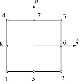
FIGURE 1. Geometry mapping technique in the FEM.
Combined with Eq. 1, 2, the shape function can be calculated by Eq. (3).
Therefore, the first-order partial differentials (FOPDs) of the shape function
The nodal value of the FOPDs is arranged by a vector form, as shown in Eq. (5).
where u is the nodal value, expressed by Eq. (6). D represents the partial differential matrices.
Its L-order partial differential function is calculated, as shown in Eq. (7).
Therefore, the aforementioned expression can be approximated, as shown in Eq. (8).
In Figure 1, a quadratic block with eight seeds can be mapped into a space
where
Then, the coordinate (mapping) can be transferred from the coordinate of the real system into that of the normalized space by Eq. (10).
The FOPDs of
where these parameters are defined by Eq. (12).
Therefore, the matrices of FOPDs are introduced by Eq. (13).
where matrices
where
It is obvious that the nodal values of the FOPDs in the physical domain can be obtained by the FOPDs in the normalized space
First, this study makes a basic assumption that the parameters of non-homogeneous materials are closely related to the coordinates in space, and in Cartesian coordinates, the relationships between displacements
For plane-stress elasticity, isotropic homogenous material mechanical coefficients are given, as shown in Eq. (16).
where
The equilibrium equations are expressed in Eq. (17).
where
Considering the matrix forms of Eqs. 13, 15, 16, the differential matrices’ form
where
For 2D elasticity, there are two kinds of boundary conditions shown as follows:
where
There are
However, at a corner joint, both the point equilibrium equations and displacement continuity conditions should be considered, as shown in Eqs 21, 22.
where
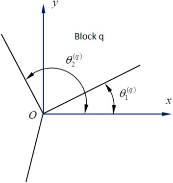
FIGURE 2. Starting and ending angles for block q at joint O.
The aforementioned method has been applied in the fields of computational solid mechanics and fluid mechanics. It can avoid grid reconstruction and effectively solve the numerical simulation problems that are difficult to analyze using the grid algorithm. It is extremely beneficial to solve large deformations such as stamping deformation, crack propagation, and fluid–solid coupling problems.
A cement concrete pavement is an important structural form of high-grade pavement. The cement concrete pavement is a multi-layer structure. The surface layer is divided into rectangular plates of finite size by joints. The scale in the plane direction is much larger than that in the thickness direction. In the analysis of the pavement structure, it is necessary to establish a reasonable mechanical model for the actual pavement structure and the stress–strain relationship of each structural layer material. At present, the pavement structure is mainly modeled by two schemes. One is the plate model, which regards the concrete surface layer as a single plate or multiple plates supported by the foundation. The other is that the three-dimensional model can consider the actual geometric shape and structural level of the pavement structure, which is an ideal model. However, under the repeated action of temperature change, humidity change, and vehicle load, the cement concrete pavement can warp and deform. The bottom surface of the edge, middle, or corner part of the panel may be separated from the top surface of the foundation and form a void beneath the slab. At the same time, the plastic deformation accumulates when the base material is pressed, which also leads to a void beneath the slab. This is similar to the problem of large deformation such as stamping deformation and crack extension. Therefore, it is feasible to analyze the fracture characteristics of the slab at the edge of the cement pavement using the aforementioned method. In this study, all codes of the MFBM were written in Fortran. The commercialized package Abaqus with subroutine UMAT was used for FEM simulation.
First, a square domain was divided into 10 × 10 cells in the model. In addition, each cell was divided into 4 × 4 Gauss points. In the normalized domain
There are two kinds of voids beneath the slab. One is the structural void, which is caused by temperature and humidity warping deformation and plastic deformation accumulation of the base. The other is the squirt mud void. Rainwater percolates into the panel bottom through joints and edges of cement concrete plates. The hydrodynamic pressure scours the top surface of the base course and then forms, disengaging under the action of traffic load. Because of the disengaging of the foundation and the traffic load, the stress state of the cement concrete pavement is extremely disadvantageous (Figure 3). In this case, the cement pavement plate is similar to a cantilever beam and produces excessive deflection and stress, resulting in the cracking of the cement concrete plate. The structural void is the origin of the squirt mud void, and the squirt mud void further develops the structural void. The two types of voids alternately or jointly drive the evolution and development of the void at the bottom of the slab. It can be seen that squirt mud is one of the main factors leading to the void and fracture of the cement concrete pavement. The most direct manifestation of the phenomenon of squirt mud is the attenuation of the subgrade modulus, which, in turn, affects the deformation of the cement concrete pavement.

FIGURE 3. Disengaging of the cement concrete pavement plate.
Based on the aforementioned situation, the progressive softening model of subgrade was established, as shown in Figure 4. The calculation parameters are shown in Table 1. The boundary conditions are as follows: AB and EF are free edges, BC and CD are simply supported edges, and DF is a fixed boundary. Assuming that the load acts on the upper edge of the first plate, the width of the load is 23 cm and the width of the pavement is 200 cm. At the same time, the immersed area is assumed to be an ellipse, which should satisfy the requirement of Eq. 24.
where a and b are the principal axis radii of the ellipse (b = 2a for this example), and x and y are the coordinates,
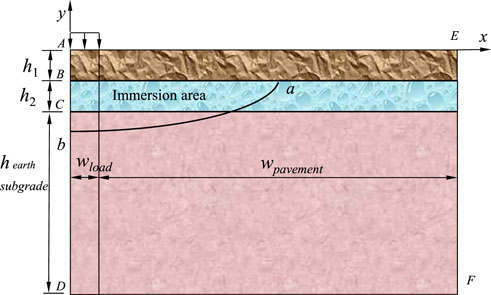
FIGURE 4. Mechanical model of the cement concrete pavement.
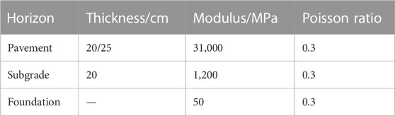
TABLE 1. Calculation parameters of the MFBM model.
The soaking subgrade materials can be regarded as a functionally graded material. The minimum value at the center position is taken, and the subgrade modulus (E) is described as a function of coordinates in Eq. (25).
where
Parameters α and β can be determined by two points of the subgrade modulus, such as
Figures 5, 6 present the dimensionless tensile stress distribution of the pavement. The dimensionless tensile stress is the ratio of surface stress to tire stress. In Figure 5, h1 = h2 = 20 cm and α is 0.25, 0.5, and 0.75. With the increase of the distance from the edge of the plate, the stress first increases and then decreases. The stress reaches the peak value at about 1.1 m from the edge of the plate, which presents the weak position of the cement concrete plate fracture. The subgrade modulus decay has an important influence on the force condition of the cement concrete plate. The peak stress reaches the maximum when α is 0.75, and the cement concrete plate is more likely to break. When α is a fixed value, the larger the size of the immersion range, the greater the peak stress. In Figure 6, h1 = 25 cm, h2 = 20 cm, and α is 0.25, 0.5, and 0.75. The change trend shown in Figure 6 is similar to that shown in Figure 5, and the stress value under the condition h1 = 0.25 m and h2 = 0.2 m is lower than that under the condition h1 = h2 = 0.2 m. With the increase of α, the stress value decreases. When α is 0.75, the reduction of the stress value reaches 27%. Figure 6 shows that increasing pavement thickness can reduce the risk of cement concrete plate fracture.
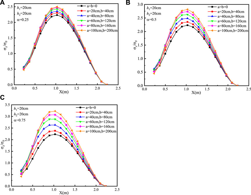
FIGURE 5. Dimensionless tensile stress distribution of the pavement using the MFBM with h1 = h2 = 20 cm: (A) α = 0.25, (B) α = 0.5, and (C) α = 0.75.

FIGURE 6. Dimensionless tensile stress distribution of the pavement using the MFBM with h1 = 25 cm and h2 = 20 cm: (A) α = 0.25, (B) α = 0.5, and (C) α = 0.75.
In other words, all the reduction of the subgrade modulus, the size of the immersion range, and the thicknesses of the pavement and subgrade can affect the cement concrete plate fracture. The smaller subgrade modulus reduced ratio, broader immersion ranges of earth subgrade, and thinner pavement and subgrade thickness are extremely disadvantageous to the force acting on the pavement plate. The maximum stress of the cement concrete pavement mainly concentrates in the range 1.05–1.15 m from the plate edge. When the stress changes to a certain extent, the pavement plate may be prone to fracture damage.
In order to verify the validity and accuracy of the MFBM, the FEM was used as a benchmark for comparative analysis. The material parameters, geometry, and boundary of the FEM are the same as those of the MFBM. Six sets of the same situations were discussed. The results of the FEM are shown in Figures 7, 8.
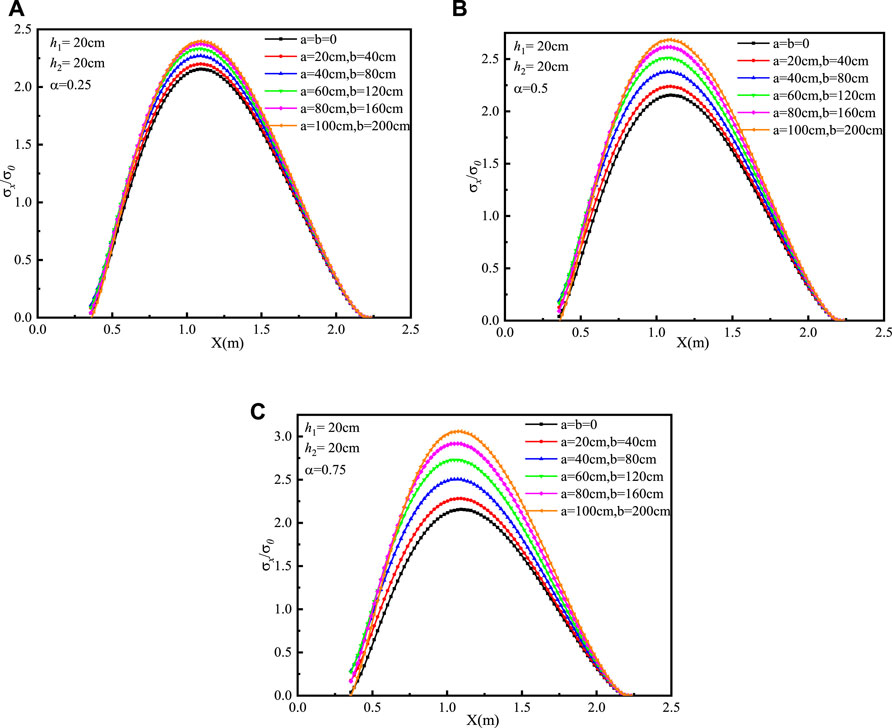
FIGURE 7. Dimensionless tensile stress distribution of the pavement using the FEM with h1 = h2 = 20 cm: (A) α = 0.25, (B) α = 0.5, and (C) α = 0.75.
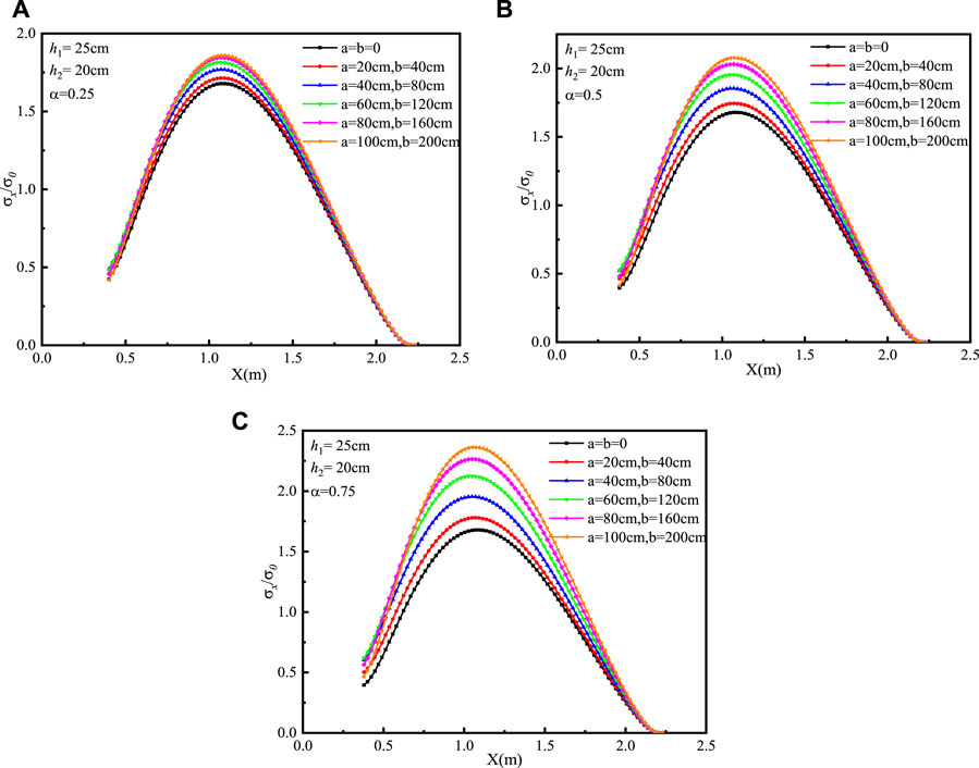
FIGURE 8. Dimensionless tensile stress distribution of the pavement using the FEM with h1 = 25 cm and h2 = 20 cm: (A) α = 0.25, (B) α = 0.5, and (C) α = 0.75.
The trend of solutions of the MFBM is the same as the FEM results, and the positions of the maximum stress determined by the two methods are basically consistent. The positions of the maximum stress of the cement concrete pavement determined by the FEM are around 1.1 m from the plate edge. The relationship between the maximum reduction of the subgrade modulus and the tendency of stress change can be identified using the FEM. The larger the maximum reduced value of the subgrade modulus, the higher the stress of the cement concrete pavement. The difference between the maximum stress values of the two methods is below 5%. With the thickness increase of the pavement plate, the position of the maximal stress is still in the same place, but the value of the stress reduces. The simulation results of the MFBM and FEM confirm that increasing the thickness of the pavement plate can decrease the degree of the plate fracture.
For further explanation, the
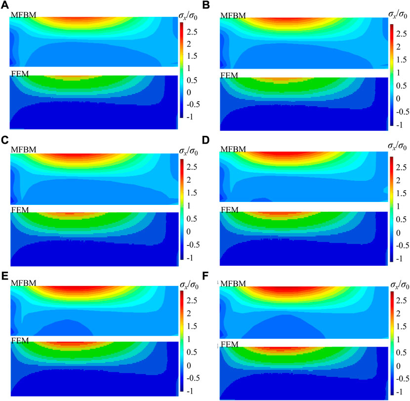
FIGURE 9. Maximum principal stress/load gradient distributions with h1 = 20 cm and h2 = 20 cm (A: the MFBM; B: the FEM): (A) a = b = 0 cm; (B) a = 20 cm and b = 40 cm; (C) a = 40 cm and b = 80 cm; (D) a = 60 cm and b = 120 cm; (E) a = 80 cm and b = 160 cm; (F) a = 100 cm and b = 200 cm.
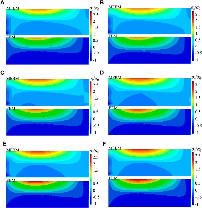
FIGURE 10. Maximum principal stress/load gradient distributions with h1 = 25 cm and h2 = 20 cm: (A) a = b = 0 cm; (B) a = 20 cm and b = 40 cm; (C) a = 40 cm and b = 80 cm; (D) a = 60 cm and b = 120 cm; (E) a = 80 cm and b = 160 cm; (F) a = 100 cm and b = 200 cm.
The subgrade modulus is an important characterization for the performance of the pavement structure. When the cement concrete pavement is in the process of scouring and disengaging, the subgrade modulus changes with the position. The progressive softening model of earth subgrade is more suitable to represent the changes in the subgrade modulus, and the MFBM model is suitable for the cement concrete pavement. Compared to the FEM, the MFBM offers advantages such as the elimination of mesh or element limitations, accurate solutions with reduced computation time, and convenience in analyzing non-homogeneous softening models.
In order to further verify the effectiveness and rationality of the proposed calculation method, we conducted a large number of road condition surveys on cement concrete pavements in Hunan, Guangxi, Guangdong, and other provinces and cities in China. The on-site cracking investigation was carried out in combination with the Highway Performance Assessment Standards by the Chinese traffic management department (JTG 5210-2018). We randomly investigated the corner fracture in different areas and traffic load sections. In addition, from the field investigation of the cement pavement plate fracture, the position of the pavement plate fracture is basically consistent with the calculated range, as shown in Figure 11. Therefore, the numerical and field results indicate that the MFBM is feasible and effective. By measuring the distance between the crack position of the corner fracture of the cement concrete pavement slab and the intersection of the longitudinal and transverse joints, it is easy to observe that the maximum stress positions of the cement concrete pavement obtained by numerical simulation agree with the measurements very well.
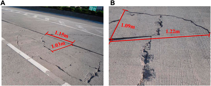
FIGURE 11. Field cracking investigation of the concrete pavement: (A) point 1; (B) point 2.
A novel MFBM was extended to cement concrete pavement engineering in this study. Compared with the FEM, the MFBM is convenient and suitable for non-homogeneous softening model analysis. The main findings are as follows:
(1) A progressive softening model established by the MFBM is capable of describing the response of a cement concrete plate with the decrease of the subgrade modulus. The proposed MFBM model is suitable for the cement concrete pavement. The position of the pavement plate fracture in the field is consistent with the range calculated by the MFBM. The FEM is one of the most powerful numerical tools for complicated problems in engineering and science. As an alternative, the meshless finite block method provides a new approach with many advantages such as efficiency and simplicity.
(2) The subgrade modulus reduction, the size of the immersion zone, and the thickness of the pavement and subgrade can affect the cement concrete plate fracture. The larger the subgrade modulus decay, the higher the stress. With the increase in the thickness of the pavement plate, the position of the maximum stress remains at the same place but the value of the stress decreases. The maximum stress of the cement concrete pavement mainly concentrates at 1.05–1.15 m of the plate edge.
However, the selection of a Lagrange series polynomial order is one issue in the MFBM. At present, meshing of the block is still a manual process in the MFBM, and the versatility needs to be further improved with complex regional models. In future works, the FBM is to be extended to apply to more complicated problems, such as elastoplasticity, thermoelasticity, and elastodynamics.
The original contributions presented in the study are included in the article/Supplementary Material; further inquiries can be directed to the corresponding author.
HW, WH, and PW contributed to the conception and design of the study. HW, WH, and YZ organized the database. PW and JL performed the statistical analysis. HW, PW, and JL wrote the first draft of the manuscript. HW, YZ, WH, and JL wrote sections of the manuscript. All authors contributed to manuscript revision, and read and approved the submitted version.
This research was funded by the National Natural Science Foundation of China, grant numbers 52278436 and 52208426, the Science and Technology Innovation Program of Hunan Province, grant number 2022RC1024, the Scientific Research Project of Hunan Provincial Department of Education for Excellent Young Scholars, grant number 20B039, the Foundation of Engineering Research Center of Catastrophic Prophylaxis and Treatment of Road and Traffic Safety of Ministry of Education, grant number kfj220402, and the National Key R&D Program of China, grant number 2021YFB2601200.
The authors declare that the research was conducted in the absence of any commercial or financial relationships that could be construed as a potential conflict of interest.
All claims expressed in this article are solely those of the authors and do not necessarily represent those of their affiliated organizations, or those of the publisher, the editors, and the reviewers. Any product that may be evaluated in this article, or claim that may be made by its manufacturer, is not guaranteed or endorsed by the publisher.
Ahmad, I., Ahmad, H., Thounthong, P., Chu, Y. M., and Cesarano, C. (2020). Solution of multi-term time-fractional PDE models arising in mathematical biology and physics by local meshless method. Symmetry 12 (7), 1195. doi:10.3390/sym12071195
Atluri, S., and Zhu, T. (1998). A new meshless local Petrov-Galerkin (MLPG) approach to nonlinear problems in computer modeling and simulation. Comput. Model. Simul. Eng. 3, 187–196.
Huang, T., Yang, J., Jin, J., Wen, P., and Aliabadi, M. (2018). Evaluation of stress intensity factors and T-stress by finite block method: Static and dynamic. Theor. Appl. Fract. Mech., 93, 222–232. doi:10.1016/j.tafmec.2017.08.009
Huang, W., Yang, J., Sladek, J., Sladek, V., and Wen, P. (2023). Meshless finite block method with infinite elements for axisymmetric cracked solid made of functionally graded materials. Eur. J. Mechanics-A/Solids, 97, 104852. doi:10.1016/j.euromechsol.2022.104852
Li, J., Zhang, J., Yang, X., Zhang, A., and Yu, M. (2023). Monte Carlo simulations of deformation behaviour of unbound granular materials based on a real aggregate library. Int. J. Pavement Eng. 24 (1), 2165650. doi:10.1080/10298436.2023.2165650
Li, J., Zheng, J., Yao, Y., Zhang, J., and Peng, J. (2019). Numerical method of flexible pavement considering moisture and stress sensitivity of subgrade soils. Adv. Civ. Eng. 2019, 7091210, 10. doi:10.1155/2019/7091210
Li, M., Meng, L., Hinneh, P., and Wen, P. (2016). Finite block method for interface cracks. Eng. Fract. Mech. 156, 25–40. doi:10.1016/j.engfracmech.2016.02.015
Li, M., and Wen, P. (2014). Finite block method for transient heat conduction analysis in functionally graded media. Int. J. Numer. Methods Eng. 99 (5), 372–390. doi:10.1002/nme.4693
Lian, Y., Zhang, X., Zhou, X., and Ma, Z. (2011). A FEMP method and its application in modeling dynamic response of reinforced concrete subjected to impact loading. Comput. Methods Appl. Mech. Eng. 200 (17-20), 1659–1670. doi:10.1016/j.cma.2011.01.019
Lin, Y., and Karadelis, J. N. (2019). Interfacial fracture toughness of composite concrete beams. Constr. Build. Mater. 213, 413–423. doi:10.1016/j.conbuildmat.2019.04.066
Liu, B., Zhou, Y., Gu, L., and Huang, X. (2020). Finite element simulation and multi-factor stress prediction model for cement concrete pavement considering void under slab. Materials 13 (22), 5294. doi:10.3390/ma13225294
Mahmoud, E., Saadeh, S., Hakimelahi, H., and Harvey, J. (2014). Extended finite-element modelling of asphalt mixtures fracture properties using the semi-circular bending test. Road Mater. Pavement Des. 15 (1), 153–166. doi:10.1080/14680629.2013.863737
Nayroles, B., Touzot, G., and Villon, P. (1992). Generalizing the finite element method: Diffuse approximation and diffuse elements. Comput. Mech. 10 (5), 307–318. doi:10.1007/bf00364252
Peng, J., Zhang, J., Li, J., Yao, Y., and Zhang, A. (2020). Modeling humidity and stress-dependent subgrade soils in flexible pavements. Comput. Geotechnics 120, 103413. doi:10.1016/j.compgeo.2019.103413
Qu, B., Weng, X. Z., Zhang, J., Mei, J., Guo, T. X., Li, R. F., et al. (2017). Analysis on the deflection and load transfer capacity of a prefabricated airport prestressed concrete pavement. Constr. Build. Mater. 157, 449–458. doi:10.1016/j.conbuildmat.2017.09.124
Rahim, A., and George, K. (2005). Models to estimate subgrade resilient modulus for pavement design. Int. J. Pavement Eng. 6 (2), 89–96. doi:10.1080/10298430500131973
Sladek, J., Sladek, V., Wen, P., and Aliabadi, M. (2006). Meshless local Petrov-Galerkin (MLPG) method for shear deformable shells analysis. Comput. Model. Eng. Sci. 13 (2), 103–117.
Sladek, V., Sladek, J., Tanaka, M., and Zhang, C. (2005). Local integral equation method for potential problems in functionally graded anisotropic materials. Eng. analysis Bound. Elem. 29 (9), 829–843. doi:10.1016/j.enganabound.2005.04.009
Wang, W., Wang, L., Xiong, H., and Luo, R. (2019). A review and perspective for research on moisture damage in asphalt pavement induced by dynamic pore water pressure. Constr. Build. Mater., 204, 631–642. doi:10.1016/j.conbuildmat.2019.01.167
Wei, H., Li, J., Wang, F., Zheng, J., Tao, Y., and Zhang, Y. (2022). Numerical investigation on fracture evolution of asphalt mixture compared with acoustic emission. Int. J. Pavement Eng., 23 (10), 3481–3491. doi:10.1080/10298436.2021.1902524
Wen, P., Aliabadi, M., and Rooke, D. (1997). A contour integral method for dynamic stress intensity factors. Theor. Appl. Fract. Mech. 27 (1), 29–41. doi:10.1016/s0167-8442(97)00005-0
Wen, P., Aliabadi, M., and Rooke, D. (1998). A variational technique for boundary element analysis of 3D fracture mechanics weight functions: Static. Int. J. Numer. methods Eng. 42 (8), 1409–1423. doi:10.1002/(sici)1097-0207(19980830)42:8<1409:aid-nme426>3.0.co;2-z
Wen, P., Cao, P., and Korakianitis, T. (2014). Finite block method in elasticity. Eng. Analysis Bound. Elem. 46, 116–125. doi:10.1016/j.enganabound.2014.05.006
Yu, S., Sun, Z., Qian, W., Yu, J., and Yang, J. (2023). A meshless method for modeling the microscopic drying shrinkage cracking processes of concrete and its applications. Eng. Fract. Mech. 277, 109014. doi:10.1016/j.engfracmech.2022.109014
Keywords: concrete pavement, meshless finite block method, progressive softening model, finite element method, subgrade modulus decay
Citation: Wei H, Zhou Y, Huang W, Wen P and Li J (2023) Fracture characteristics of a cement concrete pavement plate considering subgrade modulus decay based on a meshless finite block method. Front. Mater. 10:1157529. doi: 10.3389/fmats.2023.1157529
Received: 02 February 2023; Accepted: 28 February 2023;
Published: 14 March 2023.
Edited by:
Hui Yao, Beijing University of Technology, ChinaReviewed by:
Hao Wu, Central South University, ChinaCopyright © 2023 Wei, Zhou, Huang, Wen and Li. This is an open-access article distributed under the terms of the Creative Commons Attribution License (CC BY). The use, distribution or reproduction in other forums is permitted, provided the original author(s) and the copyright owner(s) are credited and that the original publication in this journal is cited, in accordance with accepted academic practice. No use, distribution or reproduction is permitted which does not comply with these terms.
*Correspondence: Jue Li, bGlqdWUxMjA3QGNxanR1LmVkdS5jbg==
Disclaimer: All claims expressed in this article are solely those of the authors and do not necessarily represent those of their affiliated organizations, or those of the publisher, the editors and the reviewers. Any product that may be evaluated in this article or claim that may be made by its manufacturer is not guaranteed or endorsed by the publisher.
Research integrity at Frontiers
Learn more about the work of our research integrity team to safeguard the quality of each article we publish.