 L. Yang
 P. Y. Wang
 T. Wang
- School of Electrical Engineering, Northwest University for Nationalities, Lanzhou, Gansu, China
Hall thruster is a kind of plasma optics device, which is used mainly in space propulsion. To study the influence of magnetic field on the performance of a 5 kW hall thruster, a two-dimensional PIC-MCC model was built. The Bohm diffusion was modeled by using a Brownian motion instead of the Bohm collision method and the near-wall conduction was modeled by a secondary electron emission model. When the mass flow rate is 5 mg/s, the thruster performance like thrust, efficiency and discharge current was simulated under a discharge voltage from 300 to 1,000 voltage. At first, the performance under constant magnetic field was simulated. The results showed that the magnetic field could not restrain the electrons as the discharge voltage increased. Later, the performance under varied magnetic field was simulated. The results showed that increasing the magnetic field strength with the increasing discharge voltage could restrain the electrons more efficiently, which proved that increasing the magnetic field strength is necessary for high specific impulse operation of hall thruster. At last, the performance measurement experiment of the thruster was carried out, and the experimental results verified the accuracy of the simulation results.
1 Introduction
Hall electric propulsion is one of the most mature and widely used electric propulsion technologies (Pidgeon, 2006; Levchenko et al., 2018) for satellites or deep space explorers. In recent years, new applications have emerged, taking the Starlink of SpaceX corporation (McDowell, 2020) as an example.
The magnetic field affect the density and energy distribution of the plasmas and directly decide the electric field distribution. The behavior of the plasmas then affect the beam extraction, channel erosion, thrust and efficiency. Therefore, the magnetic field in the discharge channel plays a very important role for a hall thruster. Research on the magnetic field has already been carried out widely. In the classical magnetic field design theory, radial magnetic lens are used to focus the ions, the intensity shows a positive gradient (Goebel and Katz, 2008). For a reasonable magnetic field shape, the current density should be small (Hofer et al., 2006), the magnetic field near the anode should be nearly zero, and the magnetic field gradient should be as large as possible (Chesta et al., 2001; Choueiri, 2001; Garrigues et al., 2003; Yamamoto et al., 2005; Wei et al., 2015; Zun et al., 2018; Kan et al., 2020). Although the classic radial magnetic field topology offers a high level of performance, researchers have been trying to improve the performance of the thruster by optimizing the magnetic field. Remarkable effect is the magnetic shielding technology (Mikellides et al., 2010; Goebel et al., 2011; Goebel et al., 2013; Goebel et al., 2014a; Goebel et al., 2014b; Goebel et al., 2015; Grimaud et al., 2016), which can greatly reduce sputtering corrosion of discharge channel.
The specific impulse of Hall thrusters that are now used is lower than 2500s. If the specific impulse can be increased to 2,500–3,000 s, it will bring significant benefits. This paper aims to study the influence of magnetic field on the performance of a 5 kW hall thruster LHT-140 (Figure 1) under a discharge voltage from 300 V to 1,000 V. Especially for the discharge voltage between 600 V and 1,000 V, under which the high specific impulse (2,500–3,000 s) may be realized. Thruster performance with different magnetic field distribution was simulated. The results showed that increasing the magnetic field strength is necessary as the discharge voltage increased for high specific operation of hall thruster.
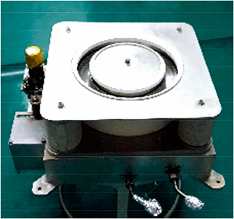
FIGURE 1. LHT-140 hall thruster.
The reminder of the paper is organized as follows: Section 2 describes the simulation model, Section 3 discusses the simulation results, conclusions and recommended future work are presented in Section 4.
2 Particle-in-cell modeling method
A classical PIC method was used to build the numerical simulation model of plasma discharge for the hall thruster (Yang et al., 2021). An artificial mass ratio of 1,000 and a mesh size of 1 mm were used in the model. The simulation area includes the entire discharge channel of hall thruster and the near plume area. The boundary of the discharge channel includes metal anode walls, ceramic walls, symmetric axis and free space. Since the magnetic field produced by the plasma is far less than that produced by the coils, only static magnetic field was used in the model. In addition to the collision between particles, the collision between particles and the wall of the discharge channel, Coulomb collision is also considered.
3 Numerical simulation results and discussion
3.1 Analysis of influence for constant magnetic field
When the propellant flow rate is 5 mg/s and the magnetic field strength is unchanged, the changes of thrust, discharge current and efficiency with the discharge voltage are shown in Figures 3–6. It can be seen that the total efficiency (shown in Figure 2) first increases with the increase of discharge voltage, reaches the maximum at 500V, and then starts to decline. Because the experimental research (Hofer and Gallimore, 2004) shows that the discharge voltage and magnetic field strength in the Hall thruster need to be matched reasonably, and the magnetic field strength must increase synchronously when the discharge voltage rises to a certain value. However, the magnetic field strength here remains unchanged. When the discharge voltage exceeds 500V, the magnetic field strength is insufficient to restrain electrons, the electrons are absorbed by the anode before they have fully collided with the propellant atoms, leading to a decrease in efficiency. When the discharge voltage increases, the ionization of propellant atoms becomes more and more sufficient, and the utilization efficiency of propellant becomes higher and higher, until the insufficient confinement of magnetic field to electrons led to insufficient ionization of propellant atoms.
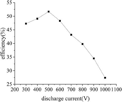
FIGURE 2. Simulated efficiency with unchanged magnetic field.
When the discharge voltage rises from 300 V to 500 V, atomic ionization becomes more and more sufficient, more and more ions are generated, and the speed is faster. Therefore, the thrust (shown in Figure 3) becomes larger and larger. When the discharge voltage rises from 600 V to 1,000 V, the ionization efficiency drops sharply, and the number of ions generated decreases. However, the ion velocity is still increasing, and the thrust (shown in Figure 3) value is still increasing, but the increasing rate becomes slow.
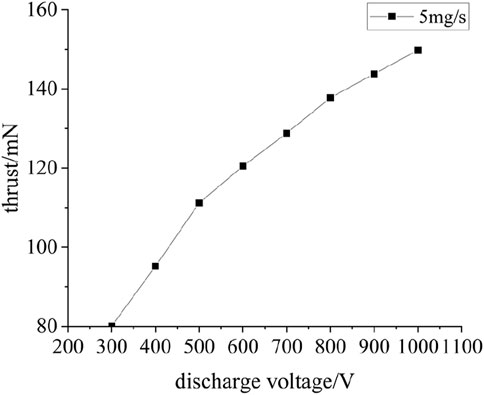
FIGURE 3. Simulated thrust with unchanged magnetic field.
The change of discharge current (shown in Figure 4) is closely related to ionization efficiency or total efficiency. When the discharge voltage rises from 300 to 500 V, the ionization efficiency increases, and more and more ions are generated. Therefore, the discharge current is also increasing. When the discharge voltage exceeds 600V, the ionization efficiency drops rapidly, and the magnetic field lacks the ability to restrain electrons, resulting in a large number of invalid electrons emitted from the cathode into the discharge channel and absorbed by the anode. That is to say, the increase of discharge current is mainly caused by the increase of invalid electron current, which does not significantly increase the thrust. Therefore, the total efficiency decreases rapidly.
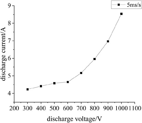
FIGURE 4. Simulated discharge current with unchanged magnetic field.
3.2 Analysis of influence for varied magnetic field
Make the magnetic field strength increase with the discharge voltage (as shown in Figure 5), and the thruster performance changes are shown in Figures 7–10.
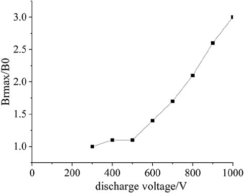
FIGURE 5. Magnetic field increased with the increase of discharge voltage.
The obvious difference with the constant magnetic field strength is that when the discharge voltage exceeds 600 V, the efficiency (as shown in Figure 6) does not decrease rapidly with the increase of the discharge voltage, but remains relatively stable (>45%). Because, with the increase of discharge voltage, the magnetic field strength is also increasing, and electrons can always be effectively constrained by the magnetic field. Therefore, the ionization efficiency does not decrease rapidly.
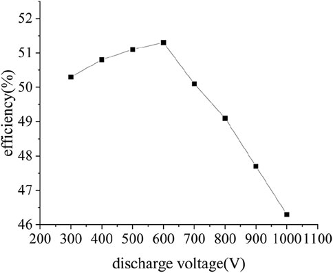
FIGURE 6. Simulated efficiency with changed magnetic field.
The increasing speed of thrust (as shown in Figure 7) did not slow down obviously when the discharge voltage exceeded 600 V.
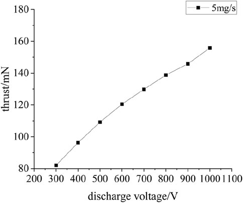
FIGURE 7. Simulated thrust with changed magnetic field.
There is also no rapid increase of invalid electron current, that is, the discharge current (as shown in Figure 8) does not increase rapidly, and the increased discharge current is mainly caused by the increase of ion current.
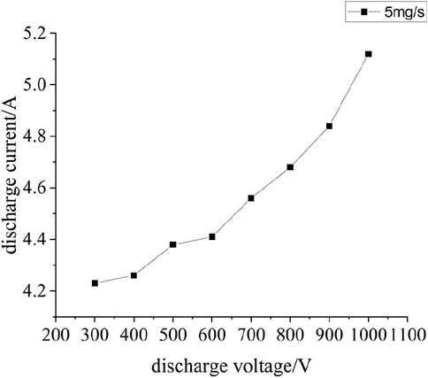
FIGURE 8. Simulated discharge current with changed magnetic field.
4 Verification of influence of magnetic field strength on thruster performance
The verification experiment was conducted (as shown in Figures 9, 10), the mass flow rate, magnetic field and discharge voltage is the same as Section 3.1, 3.2. The thrust was measured, the efficiency and specific impulse could be calculated according to thrust.
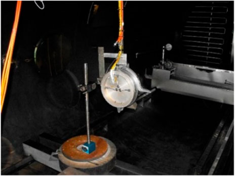
FIGURE 9. Thrust testing.
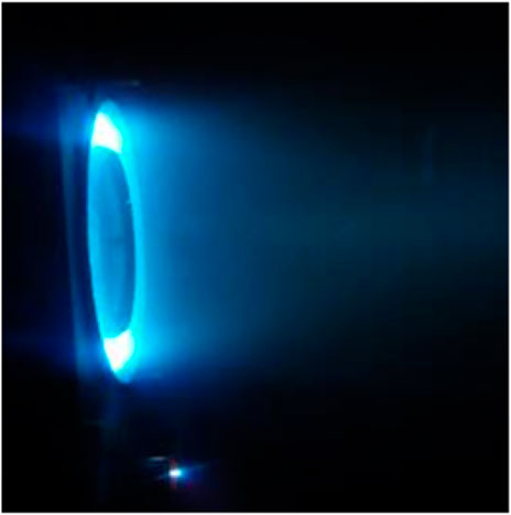
FIGURE 10. Thruster discharge.
The value of thrust (as shown in Figure 11) when the magnetic field intensity changes with the discharge voltage is greater than that when the magnetic field intensity remains unchanged. The error between experimental results and simulation results is less than 15%. When the field strength remains unchanged, the calculated value is 1.4%–9.3% smaller than the test value. When the magnetic field intensity changes, the calculated value is 1.0%–10.2% less than the test value. The main reason is that the atomic backflow effect in the vacuum chamber is not considered in this model.
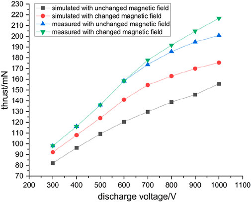
FIGURE 11. Comparison between simulated and experimental results of thrust.
5 Conclusion
The performance of the thruster, including efficiency, thrust, specific impulse and discharge current, is simulated under the conditions that the magnetic field is constant and the magnetic field strength increases with the increase of discharge voltage. The simulation results show that the magnetic field strength should increase with the increase of the discharge voltage, otherwise the restriction ability to the electrons will be insufficient. The electrons will be absorbed by the anode without full collision with the atoms in the discharge chamber, leading to the increase of the invalid electron current, resulting in the decrease of the thruster efficiency and the increase of the heat load. The subsequent thruster performance verification experiments proved the accuracy of the simulation results and relevant conclusions, and the error between the experiment and simulation calculation was less than 15%. The research in this paper explores a method to achieve ultra-high specific impulse of Hall thruster, that is, to match the high discharge voltage with reasonable magnetic field strength. It is necessary to study the influence of the configuration of magnetic field distribution in the discharge chamber on the performance of thruster, which will be carried out in the future.
Data availability statement
The original contributions presented in the study are included in the article/Supplementary Material, further inquiries can be directed to the corresponding author.
Author contributions
LY is responsible for the analysis of thrusters under different magnetic field distributions, and the analysis of relevant mechanism. PW performed the statistical analysis. TW is responsible for the design of experimental scheme. All authors contributed to manuscript revision, read, and approved the submitted version.
Funding
This work was supported by the Central Universities Basic Service Fee (31920210076) and the National Nature Science Foundations of Gansu (21JR11RA020).
Conflict of interest
The authors declare that the research was conducted in the absence of any commercial or financial relationships that could be construed as a potential conflict of interest.
Publisher’s note
All claims expressed in this article are solely those of the authors and do not necessarily represent those of their affiliated organizations, or those of the publisher, the editors and the reviewers. Any product that may be evaluated in this article, or claim that may be made by its manufacturer, is not guaranteed or endorsed by the publisher.
Supplementary material
The Supplementary Material for this article can be found online at: https://www.frontiersin.org/articles/10.3389/fmats.2023.1150802/full#supplementary-material
References
Chesta, E., Meezan, N. B., and Cappelli, M. A. (2001). Stability of a magnetized Hall plasma discharge. J. Appl. Phys. 89, 3099–3107. doi:10.1063/1.1346656
Choueiri, E. Y. (2001). Plasma oscillations in Hall thrusters. Phys. Plasmas 8, 1411. doi:10.1063/1.1354644
Garrigues, L., Hagelaar, G. J. M., Bareilles, J., oniface, C., and Boeuf, J. P. (2003). Model study of the influence of the magnetic field configuration on the performance and lifetime of a Hall thruster. Phys. Plasmas 10, 4886–4892. doi:10.1063/1.1622670
Goebel, D. M., Hofer, R. R., Mikellides, I. G., Polk, J. E., and Dotson, B. N. (2015). Conducting wall Hall thrusters. IEEE Trans. Plasma Sci. 43, 118–126. doi:10.1109/tps.2014.2321110
Goebel, D. M., and Katz, I. (2008). Fundamentals of electric propulsion: Ion and Hall thrusters. New York: Wiley.
Goebel, D. M., de Grys, K., Mathers, A., Mikellides, I. G., Katz, I., and Hofer., R. R. (2011). Magnetic shielding of the channel walls in a Hall plasma accelerator. Phys. Plasmas 18, 033501. doi:10.1063/1.3551583
Goebel, D. M., Hofer, R. R., Goebel, D. M., Mikellides, I. G., and Katz, I. (2014). Magnetic shielding of a laboratory Hall thruster. II. Experiment. J. Appl. Phys. 115, 043304. doi:10.1063/1.4862314
Goebel, D. M., Mikellides, I. G., Katz, I., Hofer, R. R., and Goebel, D. M. (2014). Magnetic shielding of a laboratory Hall thruster. I. Theory and validation. J. Appl. Phys. 115, 043303. doi:10.1063/1.4862313
Goebel, D. M., Mikellides, I. G., Katz, I., Hofer, R. R., and Goebel, D. M. (2013). Magnetic shielding of walls from the unmagnetized ion beam in a Hall thruster. Appl. Phys. Lett. 102, 023509. doi:10.1063/1.4776192
Grimaud, L., Vaudolon, J., Mazouffre, S., and Boniface, C. (2016). “Design and characterization of a 200W Hall thruster in ‘magnetic shielding’ configuration,” in Proceedings of the 52nd AIAA/SAE/ASEE Joint Propulsion Conf., Salt Lake City, UT, July 25-27, 2016 (American Institute of Aeronautics and Astronautics).
Hofer, R. R., and Gallimore, A. D. (2004). “Efficiency analysis of a high-specific impulse Hall thruster,”. Paper No 2004-3602 in Proceedings of the 40th AIAA/ASME/SAE/ASEE Joint Propulsion Conference, Ft. Lauderdale, Florida, July 11-14, 2004. AIAA. doi:10.2514/6.2004-3602
Hofer, R. R., Jankovsky, R. S., and Gallimore, A. D. (2006). High-specific impulse Hall thrusters, Part 1: Influence of current density and magnetic field. J. Propul. Power 22, 721–731. doi:10.2514/1.15952
Kan, X., Feng, T., Fuwen, L., Xia, Q., and Wang, N. (2020). Discharge instability in a plasma contactor. Plasma Sci. Technol. 22, 094011. doi:10.1088/2058-6272/ab9bf9
Levchenko, I., Bazaka, K., and Ding, Y. (2018). Space micropropulsion systems for Cubesats and small satellites: From proximate targets to furthermost frontiers. Appl. Phys. Rev. 5, 011104. doi:10.1063/1.5007734
McDowell, J. C. (2020). The low earth orbit satellite population and impacts of the SpaceX Starlink constellation. Astrophysical J. Lett. 892, ab8016. doi:10.3847/2041-8213/ab8016
Mikellides, I., Katz, I., Hofer, R., Goebel, D., de Grys, K., Mathers, A., , et al. (2010). “Magnetic shielding of the acceleration channel walls in a long-life hall thruster,” in Proceedings of the 46th AIAA/ASME/SAE/ASEE Joint Propulsion Conf. & Exhibit, Nashville, TN, 25 July 2010 - 28 July 2010 (American Institute of Aeronautics and Astronautics).
Pidgeon, D. J. (2006). “Two years On-Orbit performance of the SPT-100 electric propulsion,”. Paper No. 2006-5353 in ASSC-3: Advances in Satellite Subsystems and Components, San Diego, California, 11 June 2006 - 14 June 2006. doi:10.2514/6.2006-5353
Wei, L-Q., Han, L., Da-Ren, Y., and Guo, N. (2015). Low-frequency oscillations in Hall thrusters. Chin. Phys. B 24, 055201. doi:10.1088/1674-1056/24/5/055201
Yamamoto, N., Komurasaki, K., and Arakawa, Y. (2005). Discharge current oscillation in Hall thrusters. J. Propul. Power 21, 870–876. doi:10.2514/1.12759
Yang, L., Wang, P. Y., and Wang, T. (2021). Performance simulation of a 5kW hall thruster. Front. Mater. 8. doi:10.3389/fmats.2021.754479
Keywords: particle-in-cell, magnetic field, hall thruster, plasma optics device, high specific impulse
Citation: Yang L, Wang PY and Wang T (2023) Study on the influence of magnetic field on the performance of a 5 kW hall thruster. Front. Mater. 10:1150802. doi: 10.3389/fmats.2023.1150802
Received: 25 January 2023; Accepted: 09 March 2023;
Published: 20 March 2023.
Edited by:
Shifa Wang, Chongqing Three Gorges University, ChinaReviewed by:
Maolin Chen, Northwestern Polytechnical University, ChinaAnbang Sun, Xi’an Jiaotong University, China
Juanjuan Chen, Lanzhou Institute of Chemical Physics (CAS), China
Xianggeng Wei, Northwestern Polytechnical University, China
Copyright © 2023 Yang, Wang and Wang. This is an open-access article distributed under the terms of the Creative Commons Attribution License (CC BY). The use, distribution or reproduction in other forums is permitted, provided the original author(s) and the copyright owner(s) are credited and that the original publication in this journal is cited, in accordance with accepted academic practice. No use, distribution or reproduction is permitted which does not comply with these terms.
*Correspondence: L. Yang, eWFuZ2xlXzIzNzM3QHNpbmEuY29t