 Jun Huang
 Naifei Liu
 Zongyuan Ma
 Liang Lu4
- 1School of Earth Sciences and Engineering, Xi’an Shi-you University, Xi’an, China
- 2Shaanxi Key Laboratory of Geotechnical and Underground Space Engineering, Xi’an University of Architecture and Technology, Xi’an, China
- 3Guizhou communications polytechnic, Guiyang, China
- 4Gansu Institute of Architectural Design and Research Co, LTD, Lanzhou, China
- 5Hanjiang-to-Weihe river valley water diversion project construction Co, LTD, Xi’an, China
The stability of large-section clay tunnels is closely related to the mechanical behavior of the surrounding rock. The mechanical behavior of the surrounding rock is characterized by the coupled response of the physico-mechanical properties of the clay material and the tunnel construction conditions. Therefore, this paper proposes a numerical experimental study based on the response surface method to quantitatively link the stability of large-section clay tunnels with construction factors. It will provide a basis for quantitatively guiding the tunnel construction plan adjustment to ensure its stability. Firstly, the tunnel stability reserve is evaluated by considering the deterioration of physico-mechanical properties of clay surrounding rocks, and the relationship between the tunnel stability index and construction factors is established according to Taylor’s theorem. Secondly, the response surface method and the steepest ascent method are used to find the optimal fitting relationship between the tunnel stability reserve factor and tunnel construction factors. Finally, the analysis of a tunnel application shows that (a) the stability evaluation considering the deterioration of physical and mechanical properties of clay is well representative; (b) the “curved” region of the response of the tunnel stability reserve factor can be effectively determined by the steepest slope method; (c) for the “curved” region, a second-order response surface is more appropriate. This research will reveal the coupling relationship between tunnel stability, physico-mechanical properties of clay, and tunnel construction conditions, which will contribute to the development of intelligent tunnel construction.
1 Introduction
With the continuous development of underground space development and utilization, the large-section tunnel stability evaluation must face more complex situations and difficulties. Large cross-section clay tunnels make studying surrounding rock stability a more severe and complex challenge. Moreover, large-section excavation will cause more complex stress concentrations and deformation localization in the surrounding rock. The larger scale of underground construction, shorter construction cycles, and higher degree of construction automation and intelligence require experts and engineers to quickly, accurately, and systematically evaluate the stability of the surrounding rock and make decisions on countermeasures. All these directions and trends depend on the improvement and development of the evaluation system of the fundamental theories and methods for the large-section tunnels’ stability.
Theories and methods of stability analysis of large-section clay tunnels are also based on the stability of ordinary tunnels (Höfle et al., 2008; Lü et al., 2020; Song et al., 2021; Xue et al., 2023b). The tunnel stability problem is derived from the difficulties encountered in the construction of underground projects (Huang et al., 2019; Liu et al., 2020; Kumar and Sahoo, 2021; Zhang et al., 2022b). The research work on it is also one of the essential manifestations of the close connection between theory and reality (Lee et al., 2006; Wilson et al., 2011; Tyagi et al., 2018; Rahaman and Kumar, 2020; Li et al., 2021). Those problems have been analyzed and summarized by researchers and engineers, e.g., the classification and failure mechanism of the surrounding rock by observing and monitoring the mechanical indicators and anomaly phenomena of the surrounding rock during the tunnel construction process. The calculation formulas of the surrounding rock pressure and the stress-strain relationship of the surrounding rock are established via some idealized assumptions (Bai et al., 2019; Zhong and Yang, 2020; Hou et al., 2022; Man et al., 2022; Xue et al., 2023a). The changes in the mechanical state inside the surrounding rock during the construction process of the tunnel and underground engineering are very complicated to be recognized. A series of indoor experimental studies, including the centrifuge tunnel model through similar models in the chamber, are processed (Juneja et al., 2010; Alavi Gharahbagh et al., 2014; Song and Marshall, 2020; Bai et al., 2021a; Li et al., 2021). The researchers also used numerical models of tunnels through finite elements, discrete elements, and et al. to carry out stability analysis related to the mechanical state of the surrounding rock and the most likely failure form (Zhang et al., 2011; Roateşi, 2014; Ukritchon et al., 2017; Lü et al., 2018; Liu et al., 2022b; Hou et al., 2022; Xue et al., 2023b). The advantages of numerical analysis are becoming more and more evident as technology advances, especially in terms of geometry, boundary conditions, and visualization of results, making it a powerful tool.
All research and practice are aimed at better ensuring the stability of the construction solution to support the tunnel surrounding rock (Dias, 2011; Pan and Dias, 2017; Park et al., 2017; Zare Naghadehi et al., 2019; Bai et al., 2021b; Zhang et al., 2022a). Thus, researchers have conducted various studies on the mechanical state, deformation state, and stability of the surrounding rock through theoretical, experimental, numerical, and field monitoring methods to study the tunnel burial depth, hole diameter, excavation plan, and support plan (Tyagi et al., 2018; Antão et al., 2021; Kumar and Sahoo, 2021; Shiau and Al-Asadi, 2022). These research results have greatly enriched and improved the knowledge of tunnel construction theory and practice.
Tunnel stability research work has made significant progress after years of development. The underground projects, including tunnels, are faced with the difficulties posed by construction in high-risk environments where geological engineering problems are frequent at the early stage of tunnel construction (Rojat et al., 2015; Weng et al., 2020; Yertutanol et al., 2020; Xue et al., 2022). Traffic tunnels are also trending toward larger cross-sections, and the requirement for faster and better construction periods and the engineers need to pay more attention to the role of construction solutions in securing tunnel stability. Artificial intelligence, construction intelligence, and automation will also bring new changes to tunnel construction (Mahmoodzadeh et al., 2020; Higgins and Stathopoulos, 2021; Liu et al., 2022a; Ayawah et al., 2022; Baghbani et al., 2022; Soranzo et al., 2022). Following these trends, such as rapid decision-making mechanisms for construction solutions, cannot be separated from the development of methods for analyzing tunnel stability foundations.
Research work in these areas has contributed significantly to developing tunnel stability theory, methods and practice. However, the current research results are difficult to play a more significant role in construction automation, intelligence, and rapid decision-making. Therefore, with the advantage of numerical analysis tools, this paper proposes a numerical experimental study based on response surface design for quantitative linkage between stability and construction factors at the face of large-section clay tunnels. It should be provided a systematic direction for developing decision-making methods, and the techniques and ideas used will contribute to the realization of tunnel construction intelligence and automation.
2 Stability evaluation via the deterioration of clay mechanical properties
2.1 The stability index of clay surrounding rocks
The stability evaluation index for large-section clay tunnels is quantitative, and it can estimate the variability between the mechanical state of the surrounding rock after tunnel excavation and its limit state.
(1) The stability reserve factor for the large cross-section clay tunnel
Firstly, the actual mechanical state of the surrounding rock at one point after tunnel excavation is S0 and the limit state at that point is SL, by analogy with the slope safety factor, the calculated expression for the tunnel stability reserve factor Fs is given as follows.
The tunnel stability reserve factor can be applied to different geological conditions, environmental conditions, additional loading factors, et al., it only depends on the actual mechanical state and the limit state of the surrounding rock and does not depend on the constitutive model. Therefore, it is well suited for the stability evaluation of a large cross-section clay tunnel.
Figure 1 gives the correlation between the tunnel stability reserve factor based on Eq. 1 and the actual mechanical state of the surrounding rock. The ultimate state of the surrounding rock is closely related to the physico-mechanical properties of the clay. The process of deterioration of the physico-mechanical properties of the clay is specifically characterized as a change in the limit state of the surrounding rock. When the physico-mechanical properties of the surrounding rock remain unchanged, then the actual mechanical state of the surrounding rock can be adjusted to meet a given tunnel stability reserve factor.

FIGURE 1. Diagram of the deterioration of clay mechanical properties.
(2) Mechanical state of the surrounding rock in a large-section clay tunnel.
A tunnel is excavated in a clay stratum, and the stress state and strain state of a point in the surrounding rock is the response of the internal forces and deformation of the surrounding rock under the generalized load. Therefore, the mechanical state of the surrounding rock can be characterized by its stress state and strain state.
The stress state and strain state of a point, M(x, y, z), in the surrounding rock of a clay tunnel can be expressed by the stress component and strain component of the element at that point (shown in Figure 2).
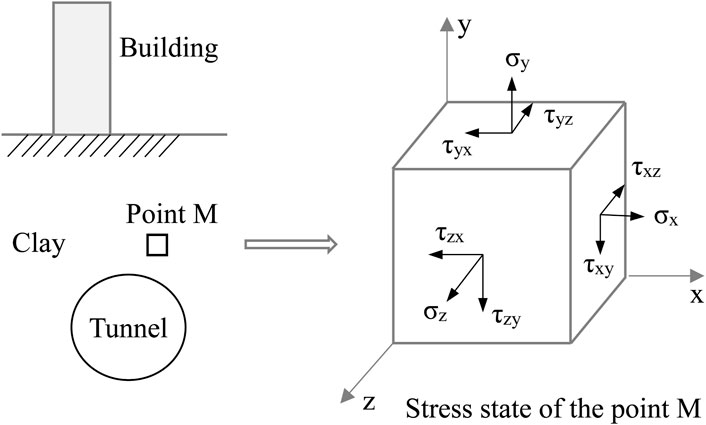
FIGURE 2. Stress state at a point in the clay tunnel surrounding rocks.
The following equation can express the relationship between the mechanical state of a point in the surrounding rock and its stress state and strain state.
S is the mechanical state tensor of a point in the surrounding rock after tunnel excavation. If the constitutive model is determined, the stress and strain state is the relevant variables. Then the mechanical state function of surrounding rocks can be expressed by one of the stress or strain states (for example, Eq. 4).
For the clay tunnel surrounding rocks, failure of surrounding rock is caused by shear stress reaching the shear strength of clay. The stress state of a point in the clay surrounding rock can be replaced by the shear stress in Eq. 3, and the strain state is retained. The mechanical state function of the surrounding rock can be expressed by the following.
Therefore, the actual mechanical state of a point in the surrounding rock under the unloading effect of tunnel excavation can be expressed as follows.
Where
(3) The limit state of the surrounding rock in a large cross-section clay tunnel
The failure of the tunnel due to insufficient strength surrounding rock can be regarded as the mechanical state of the surrounding rock exceeding the limit state of bearing capacity. The failure of the tunnel due to excessive deformation of the surrounding rock can be regarded as the mechanical state of the surrounding rock exceeding the serviceability limit state. The tunnel limit state SL has three situations of expression shown as follows.
(a) The stress state at a point in the surrounding rock reaches the limit,
(b) The strain state of the surrounding rock reaches the limit at a certain point,
(c) The stress and strain state at a point of the surrounding rock reaches the limit simultaneously,
According to Eq. 1: when
Although Eq. 1 is a general expression, difficulties are encountered in the calculation process. The theoretical calculation of the mechanical state of the surrounding rock caused by tunnel excavation is relatively tricky. The shear strength can be simply determined by Coulomb’s law. Therefore, this paper uses the strength reduction method (Meng et al., 2019; Nie et al., 2019; Abra and Mahdi, 2022) and the strength-deformation parameter deterioration method (Huang et al., 2023) to calculate the tunnel stability reserve factor. The principle of the calculation of the tunnel stability reserve factor is simply represented by a Mohr circle and the strength envelope in Figure 3.
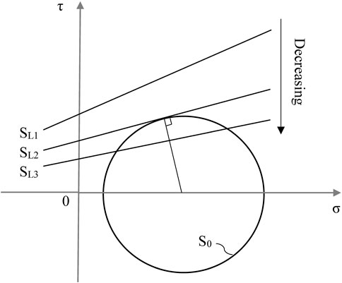
FIGURE 3. Calculation method of the deterioration of clay mechanical properties based on Mohr circle.
2.2 Factor analysis for the stability of tunnel construction
The factors of the stability of a large-section clay tunnel can be divided into internal and external factors. The tunnel stability reserve factor can be determined by Eq. 1. The mechanical conditions and the surrounding rock’s limit state also affect the tunnel stability. Equation 1 can be expressed by the following implicit function.
The complete set of influence factors of tunnel stability is U, and the groups of intrinsic and extrinsic factors are
The internal and external variables in Eq. 7 contain at least one factor. The equation is not strictly a binary function.
(1) Internal factors affecting the stability of a large-section clay tunnel
The physical and mechanical properties of the surrounding rock (mainly including strength parameters, deformation parameters, weight, water content, et al.) are inherent and are internal factors affecting the stability of the tunnel. When the surrounding rock is clay, its physical and mechanical properties should conform to Coulomb’s law. And the shear strength of the surrounding rock can be determined by the strength parameters (Strength parameters are a collective term for the mechanical properties that affect the shear strength of clays) i.e., cohesion and angle of internal friction. The deformation of clay is determined by Young’s modulus and Poisson’s ratio via the generalized Hooke’s law. The deformation of the surrounding rock can be referred to as deformation parameters. The strength parameter and deformation parameter are the characterization of the inherent properties of materials.
Taking the limit state of the surrounding rock and the limit state of regular condition into account, the general expressions of the limit state of the surrounding rock at one point concerning the strength parameter and the deformation parameter are shown below.
Where
The above equations are supported by strength theory, and the constitutive relationship verifies their rationality. The clay’s bulk weight and water content may also be critical internal factors. To make the analysis more focused, their effects on strength and deformation are not considered here.
(2) External factors affecting the stability of a large cross-section clay tunnel
Tunnel excavation causes stress concentration or strain localization in the stratum in static equilibrium due to changes in structural form, boundary conditions, loading effects, et al. Moreover, the mechanical response (also called mechanical state) of the surrounding rock is the external condition and also is the key factor of the stability state of the surrounding rock. Therefore, the external factors affecting the stability of the tunnel are also the external conditions affecting the mechanical state of the surrounding rock, such as the action of additional loads on the surrounding rock, boundary conditions, the form of tunnel support, geometry, et al. These external conditions are closely related to the tunnel structure design plans, excavation plans, and support plans, which are collectively referred to as construction factors.
For a more focused subsequent analysis and to make the expressions more concise, the construction factors are here divided into three categories. For large cross-section clay tunnels, it is assumed that the set of factors related to the structural design scheme (e.g., burial depth, hole diameter, section shape, et al.) is A, which satisfies
The actual strain state at this point can be expressed as follows.
(a) When the stress-strain relationship is linear elastic
(b) When the stress-strain relationship is non-linearly elastic
Regardless of the stress-strain relationship, Eq. 6 can be further expressed as:
The joint analysis of Eq. 7 with Eqs. 8–12 leads to an implicit function in which more explicit variables can express the tunnel stability reserve factor.
When the surrounding rock material is the same, the stability state of the tunnel (which can also be considered as the actual mechanical state of the surrounding rock) must be different for different structural design plans, excavation plans, or support plans. Thus the tunnel stability index (i.e., the tunnel stability reserve factor) must be different. The engineers can estimate the current state characteristics of the tunnel via the quantitative evaluation of tunnel stability during the actual tunnel construction process. The stability evaluation guides the design, adjustment, or optimization of the construction can be planned to ensure the safety and stability of the tunnel, which is the most crucial goal pursued by engineers. Therefore, it is essential to determine the relationship between tunnel stability indicators and these main construction factors.
2.3 General formula of the clay tunnel stability index and construction factors
Large cross-sectional clay tunnels with little change in the distribution of the surrounding rock material can be regarded as interval sections of the same material. The tunnel stability reserve factor is closely related to the construction factors. At this point, Eq. 13 can be simplified to the following function.
Equation 14 reflects that we can use the tunnel stability reserve factor as a stability index while constructing the large cross-section clay tunnel. In developing a specific construction plan, this indicator can be used as a quantitative basis for the optimization and adjustment of the construction plan, and engineers can make construction decisions to optimize the safety and stability of the tunnel. The premise of all this is to determine the response of the tunnel stability reserve factor to these construction factors. α, β, and η represent one or more factors of a particular type. Therefore, to keep the discussion simple and general, α, β, η are still used here as a single variable for the analysis.
Any construction scenario for any large cross-sectional clay tunnels can be represented by a set of construction factors
According to the assumption of homogeneity of the surrounding rock material and physical-mechanical continuity, a higher-order partial derivative of Fs exists in the definition domain U. If the initial construction solution is denoted as
Is the Lagrange residual term that can be used to estimate the error if there exists
Where,
Generally, as n increases, the higher the accuracy of the formula, but this will cause a rapid increase in the calculation and analysis of the computational effort, making its specific application difficult to promote; numerical analysis also shows that not higher-order Taylor formula will be able to achieve better accuracy, such as the Runger phenomenon. For the entire definition domain, complex functions are difficult to describe accurately with a simple Taylor formula. The first-order or second-order Taylor formula can follow the accuracy requirements in a relatively small sub-domain. The better fitting formula between the tunnel stability reserve factor and the many construction factors can be processed based on the above analysis. Equation 16 has a more apparent guiding meaning and practical value, which is further described as follows.
The initial construction scenario characterized by the main construction factors is
(a) If
(b) If
To ensure a stable and safe tunnel construction, this faced two kinds of construction plan adjustments.
(a) When
(b) When
(c) When
Although we obtained the multivariate Taylor formula for tunnel stability index and construction factors, the procedure is still unknown. It is necessary to find their exact or approximate relationship equations.
3 Response surface method for construction stability
It is difficult to obtain the exact expression and solve for all partial derivatives in Eq. 16 directly. In this study, we tried to fit the relational equation and to ensure the accuracy of the fitted expressions. The valid data requires efficient and reliable experimental design or field monitoring techniques, the experimental design is relatively more economical and reliable and has less chance of error. The experimental method cannot be separated from the experimental model. Experimental models can be divided into numerical, similar, and in situ models. In contrast, numerical experiments have been applied and shown to be superior in many engineering practices, so this paper also relies on the experimental design of the numerical tunnel model to obtain its fitted relationship.
For large-section tunnels, the design of the construction plan is closely related to the selection of construction factors. These factors are both independent of each other and interact with each other. The response surface method (RSM) can be better applied to the experimental study of the relationship between the stability index and multiple factors of tunnel construction because its process optimization not only considers the interaction between the factors better but also allows for a more approximate relationship. This optimization process is also very compatible with the idea of construction plan optimization. This paper considers the tunnel stability reserve factors as the response parameter, and the set of construction factors corresponding to any construction scheme is
3.1 First-order response surface analysis of tunnel stability
Suppose the variables
3.1.1 Determining the range of variation in each factor and coding the transformation
The range of these variables in the construction factors varies, and the settings may differ considerably. All variables can be linearly transformed (also called coding transformation). The region of these factors is transformed into a “cube” with the center as the origin, and the coding can solve the design problems caused by the different scales. The coding transformation method is described below.
Let the ith variable
All variables
3.1.2 Experimental arrangement
After coding transformation in the factors, the number of their levels can now be considered as the upper and lower two levels (i.e. −1 and 1). The full factorial experiment can be used directly; if there are more than three construction factors and no more than seven, the two-level orthogonal table (
3.1.3 The steepest ascent method
The “curved” response region of the tunnel stability reserve factor is found by the steepest ascent method.
(a) When the fit of the first-order response model in the defined domain is not significant, it directly reflects the curvature of the response in that interval. The steepest ascent method allows a better search for the region where the curved is most pronounced.
(b) When the fit of the first-order response model in the defined domain is significant, it indicates that the first-order response model can be used in the interval. It is necessary to determine the “curved” part by the steepest ascent method and to design and calculate the second-order response experiment for the curved region. Figure 4 shows the calculation principle of the steepest ascent method and its path.
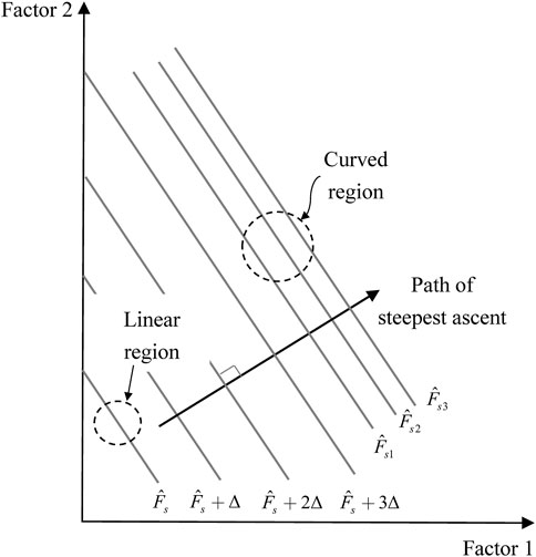
FIGURE 4. Schematic diagram of the steepest ascent path in the “curved” response region.
3.2 Second-order response surface analysis of tunnel stability
The region corresponding to these construction factors is designed and calculated by the second-order model when the response surface of the tunnel stability reserve factor is close to or “curved”. In this case, there is a non-linear relationship between the stability reserve factor and these factors. In most cases, a second-order model is appropriate, as shown below.
Additional experimental points are usually required in this region
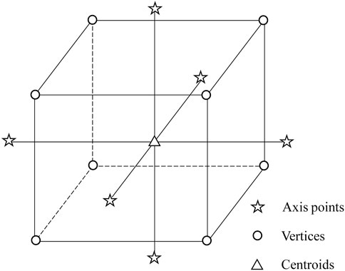
FIGURE 5. The “cube” experimental point of the central composite design.
The construction factors are coded and converted using Eq. 21. For CCD, each construction factor is now at three levels (i.e., high, medium, and low levels) of −1, 0, and 1. The distance of the axis point from the center point is assumed to be coded as
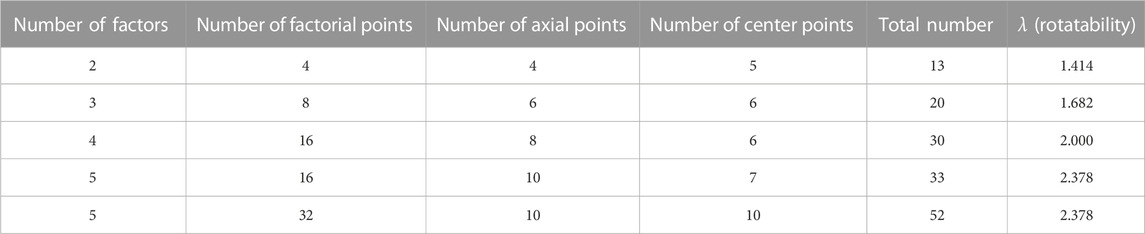
TABLE 1. Number of experimental points of the CCD (Number of factors <6).
The number of experimental points in the CCD is more obviously influenced by some factors (as shown in Table 1). The distance
Nf is the number of factors in the CCD.
4 Example application of the construction stability of a large-section tunnel
4.1 Project example overview
A new tunnel somewhere on the Lanzhou Metro Line No. 3 multiplex is used as the study object. The tunnel is 970 m long and will cross the existing high-speed railway line at DK297 + 350 DK298 + 320. The tunnel axis is approximately 90° orthogonal to the high-speed railway line axis, and the minimum distance between the tunnel vault and the high-speed railway line is only 12 m. The new tunnel is mainly in the loess stratum. The tunnel in this scope is constructed by the shield method with a whole cross-section, and the excavation area is about 180 m2, which is typical of a large cross-section shield tunnel.
The tunnel construction adopts the joint overrun support of a dense row of large pipe roofs and reinforcement bolts to ensure the stability of the tunnel construction and the minimum impact on the high-speed railway line. The row of large pipe roofs is constructed within a 150° angle and a 25 mm diameter reinforcement cage is inserted and filled with cement mortar to increase the stiffness (10 m in length, 180 mm in diameter, 10 mm in wall thickness, and 22 mm in diameter, 8 m in length and 1.2 m in spacing, in the plum-shaped arrangement).
The construction factors affecting tunnel stability in this paper mainly include the length of the pipe roof, the support pressure on the face, and the additional load on the ground. These construction schemes involve more complex conditions and are not convenient to use directly, a simplified approach is adopted in this paper to deal with them. For example, the length of the pipe roof is expressed as distance l from the face, the support pressure on the face is described as p, and the additional load on the ground is denoted as q, as shown in Figure 6.
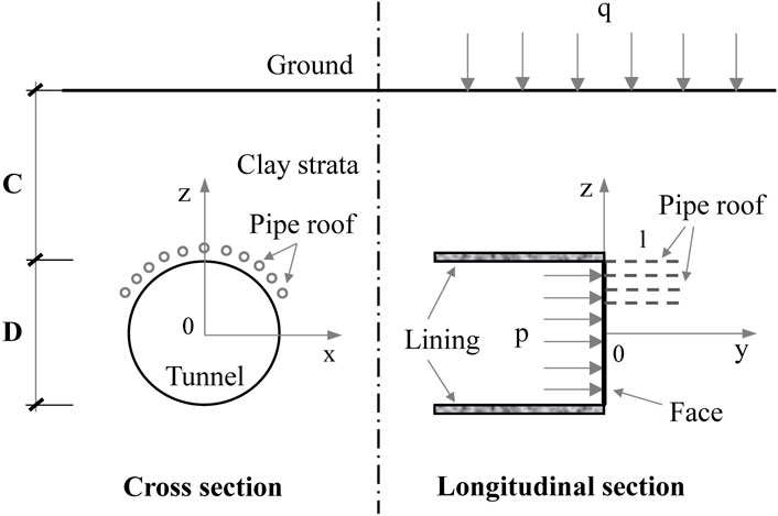
FIGURE 6. Tunnel configuration and construction factors.
4.2 Numerical experimental design and analysis
The surrounding rock is a homogeneous clay layer and follows the ideal elastic-plastic constituted relationship. The numerical model is long enough in the axial direction, and the face is not less than five times the diameter of the hole from the left to the right boundaries to weaken the influence of the distal boundary on the analysis. The bottom of the tunnel arch is much larger than three times the tunnel’s diameter from the bottom edge. The other geometric dimensions of the numerical model (the diameter C = 20 m and the buried depth D = 14 m) and the initial clay physical and mechanical parameters are shown in Figure 6; Table 2.
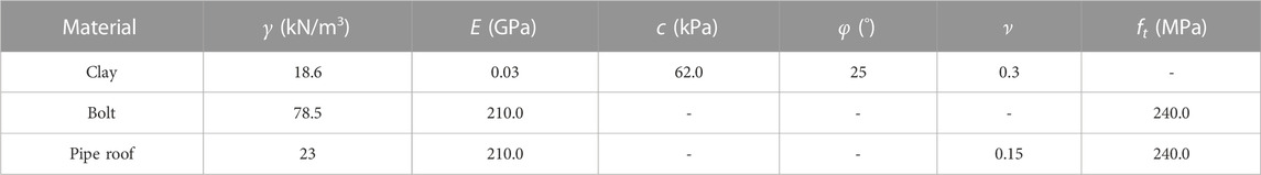
TABLE 2. Physico-mechanical parameters of surrounding rocks and initial support.
The ideal tunnel model and the initial construction parameters are kept unchanged. The influence of the three construction factors (the length of the pipe roof l, the face support pressure, and the additional load on the ground as shown in Figure 6) on the stability of the face is analyzed. The region U1,
The response surface method is used for numerical experimental design and function fitting. The finite element strength reduction method solves the tunnel stability reserve factor Fs. The finite element failure criteria are based on the unified use of the plastic zone penetration as the tunnel instability characteristics to avoid errors in the results. The different center point data acquisition is mainly achieved through variable grid size.
The full factorial experiments fitting the first-order response model were first arranged, and the obtained tunnel stability reserve factors are listed in Table 3. Note also that the tunnel stability reserve factor is calculated by the strength reduction method.
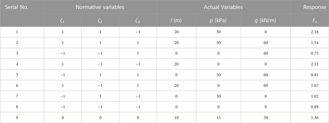
TABLE 3. Response of experimental design and stability factor of safety in the initial region U1.
The resulting fit yields a first-order response model as:
The fitted first-order response model, represented by the canonical variables, is
Analysis of variance (ANOVA, R2 = 96.3%) shows that the first-order response model fits significantly in region U1. The ratio of the main effects of the pipe roof overrun support length, and support pressure on the face. The additional ground load will be further analyzed in the “curved” region U2 using the steepest ascent method as follows:
The steepest ascent method is conducted by a path of integer multiples of the step length Δ with the center point as the initial point, i.e.,
Figure 7 shows the stability factor of safety for the face at each step along the steepest ascent path. The rate of increase in response is observed to be faster up to step 4. The rate of growth in the stability factor of safety remains essentially the same for each subsequent step. There is a significant “curved” after step 4, which requires a central composite design in the corresponding region U2. The region U2 for further fitting of the second-order response is
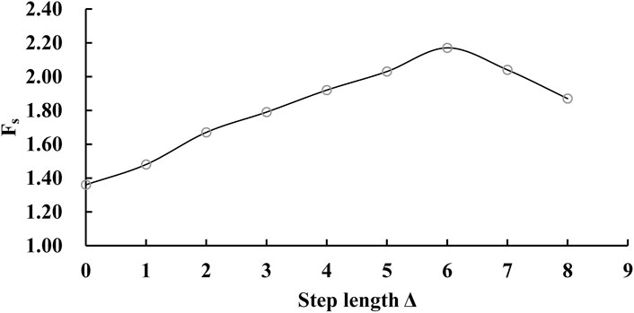
FIGURE 7. The variation pattern of the tunnel stability reserve factor with step length along the steepest ascent path.
Second-order response model for the tunnel stability reserve factor in region U2.
The results of model fit via the analysis of variance (ANOVA, R2 = 96.0%) show that the second-order model (Eq. 28) is a suitable approximation to the entire surface and a more accurate fit of the function
Table 4 presents the results of the tunnel stability reserve factor of experimental points by CCD, and is used for second-order response fitting. The best-fitting expression can be obtained by effective tracing analysis of construction factors on these response surfaces (shown in Figure 8). The best-fitted model can be obtained in this numerical test, i.e., Eq. 28, which also reflects the strength of the interaction effect from the shape of contour lines in Figure 8. The interaction between the support pressure of the face and the additional load on the ground is more significant, which is consistent with the characteristics of their regression coefficients in Eq. 28. The contour line in Figure 8C is closer to the elliptical type, so the interaction between the support pressure of the face and the additional surface load is more significant. The response surfaces from Figure 8A ∼ (c) are a reasonable verification of the consistency and validity of Eq. 28 to the numerical tests. The corresponding construction plan can be determined more quantitatively according to this method in the early design and construction evaluation periods, thus ensuring the tunnel’s stability and safety.
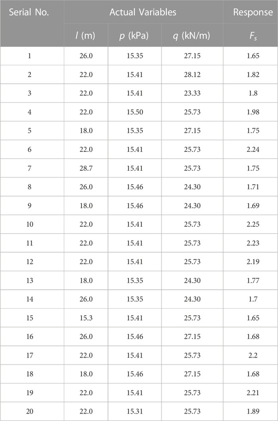
TABLE 4. Experimental design and response of CCD within region U2.
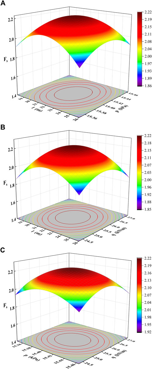
FIGURE 8. Response surface of the tunnel stability reserve factor in the region U2. (A) Response surface corresponding to support length l and support pressure p. (B) Response surface corresponding to support length l and ground surcharge load q. (C) Response surface corresponding to support pressure p and ground surcharge load q.
5 Conclusion
In this paper, experimental schemes are designed based on the response surface method through numerical model tests of the large-section clay tunnel and revealing the quantitative relationship equations between tunnel stability index and construction factors. The main conclusions based on the theoretical analysis, experimental design, and example applications are listed below.
(1) The physico-mechanical properties of the surrounding rock are regarded as internal factors and construction factors as external factors. Considering the deterioration of the physical and mechanical properties of clay, the tunnel stability reserve can be simply evaluated. The relationship between the tunnel stability index and the construction factors is constructed as a function via Taylor’s formula.
(2) An experimental design of multivariate response between the tunnel stability reserve factor and some construction factors is processed by the response surface method. It explicitly gives the analysis methods and procedures for the first-order and second-order response surfaces of tunnel stability. The implicit function expressions are fitted to reveal the multivariate second-order response relationship between them.
(3) This numerical experimental design method can be well applied to study the construction stability of large-section clay tunnels. It may provide a research method with better theoretical and practical values to engineering practice. The research could provide a basis for guiding the construction scheme and provide some technical support for the development of intelligent and automatic tunnel construction.
Data availability statement
The original contributions presented in the study are included in the article/supplementary material, further inquiries can be directed to the corresponding authors.
Author contributions
JH was in charge of conceptualization, funding acquisition, writing of the original draft, and editing. NL was in charge of data resources and analysis. ZM was in charge of the development of the mathematical model of the research and overall supervision of the whole research investigation. LL was in charge of the experimental design. KD was in charge of the post-processing data.
Funding
This work was supported by the Science and technology innovation fund project of Hanjiang-to-Weihe river valley water diversion project construction Co., LTD (No. 2020302), Open Research Fund Program of State Key Laboratory of Eco-hydraulics in Northwest Arid Region (No. 2018KFKT-16), Open Research Fund Program of Shaanxi Key Laboratory of Geotechnical and Underground Space Engineering (No. YT202009), the Shaanxi Natural Science Foundation (No. 2022JM-190). The authors declare that this study received funding from Hanjiang-to-Weihe river valley water diversion project construction Co. LTD. The funder had the following involvement in the study: the funder participated in the data processing.
Acknowledgments
The authors would like to thank Shaanxi Key Laboratory of Petroleum Accumulation Geology for providing high-performance computing devices. Xingwang NL provided invaluable assistance in the conduct of the deformation surveys.
Conflict of interest
LL was employed by Gansu Institute of Architectural Design and Research Corporation Limited: KD was employed by Hanjiang-to-Weihe River Valley Water Diversion Project Construction Corporation Limited.
The remaining authors declare that the research was conducted in the absence of any commercial or financial relationships that could be construed as a potential conflict of interest.
Publisher’s note
All claims expressed in this article are solely those of the authors and do not necessarily represent those of their affiliated organizations, or those of the publisher, the editors and the reviewers. Any product that may be evaluated in this article, or claim that may be made by its manufacturer, is not guaranteed or endorsed by the publisher.
References
Abra, O., and Mahdi, B. F. (2022). Strength reduction design method for reinforced concrete structures: Generalization. Eng. Struct. 258, 114134. doi:10.1016/j.engstruct.2022.114134
Alavi Gharahbagh, E., Rostami, J., and Talebi, K. (2014). Experimental study of the effect of conditioning on abrasive wear and torque requirement of full face tunneling machines. Tunn. Undergr. Space Technol. 41, 127–136. doi:10.1016/j.tust.2013.12.003
Antão, A. N., Vicente da Silva, M., Monteiro, N., and Deusdado, N. (2021). Upper and lower bounds for three-dimensional undrained stability of shallow tunnels. Transp. Geotech. 27, 100491. doi:10.1016/j.trgeo.2020.100491
Ayawah, P. E. A., Sylvanus, S. N., Azure, J. W. A., Kaba, A. G. A., Anani, A., Bansah, S., et al. (2022). A review and case study of Artificial intelligence and Machine learning methods used for ground condition prediction ahead of tunnel boring Machines. Tunn. Undergr. Space Technol. 125, 104497. doi:10.1016/j.tust.2022.104497
Baghbani, A., Choudhury, T., Costa, S., and Reiner, J. (2022). Application of artificial intelligence in geotechnical engineering: A state-of-the-art review. Earth-Science Rev. 228, 103991. doi:10.1016/j.earscirev.2022.103991
Bai, B., Nie, Q., Zhang, Y., Wang, X., and Hu, W. (2021a). Cotransport of heavy metals and SiO2 particles at different temperatures by seepage. J. Hydrology 597, 125771. doi:10.1016/j.jhydrol.2020.125771
Bai, B., Yang, G., Li, T., and Yang, G. (2019). A thermodynamic constitutive model with temperature effect based on particle rearrangement for geomaterials. Mech. Mater. 139, 103180. doi:10.1016/j.mechmat.2019.103180
Bai, B., Zhou, R., Cai, G., Hu, W., and Yang, G. (2021b). Coupled thermo-hydro-mechanical mechanism in view of the soil particle rearrangement of granular thermodynamics. Comput. Geotechnics 137, 104272. doi:10.1016/j.compgeo.2021.104272
Dias, D. (2011). Convergence-confinement approach for designing tunnel face reinforcement by horizontal bolting. Tunn. Undergr. Space Technol. 26 (4), 517–523. doi:10.1016/j.tust.2011.03.004
Higgins, S., and Stathopoulos, T. (2021). Application of artificial intelligence to urban wind energy. Build. Environ. 197, 107848. doi:10.1016/j.buildenv.2021.107848
Höfle, R., Fillibeck, J., and Vogt, N. (2008). Time dependent deformations during tunnelling and stability of tunnel faces in fine-grained soils under groundwater. Acta Geotech. 3 (4), 309–316. doi:10.1007/s11440-008-0075-y
Hou, C., Pan, Q., Xu, T., Huang, F., and Yang, X. (2022). Three-dimensional tunnel face stability considering slurry pressure transfer mechanisms. Tunn. Undergr. Space Technol. 125, 104524. doi:10.1016/j.tust.2022.104524
Huang, J., Liu, X., Ma, Z., Lv, G., and Dang, K. (2023). The stability evaluation of clay tunnels via the non-linear deterioration of physical and mechanical properties of surrounding rocks. Front. Earth Sci. 10. doi:10.3389/feart.2022.1112410
Huang, M., Wang, H., Yu, J., and Tang, Z. (2019). Undrained stability analysis of a plane strain circular tunnel using streamline velocity fields. Int. J. Geomechanics 19 (5), 06019006. doi:10.1061/(ASCE)GM.1943-5622.0001395
Juneja, A., Hegde, A., Lee, F. H., and Yeo, C. H. (2010). Centrifuge modelling of tunnel face reinforcement using forepoling. Tunn. Undergr. Space Technol. 25 (4), 377–381. doi:10.1016/j.tust.2010.01.013
Kumar, B., and Sahoo, J. P. (2021). Stability of unsupported circular tunnels in anisotropic normally and over consolidated saturated clay. Comput. Geotechnics 135, 104148. doi:10.1016/j.compgeo.2021.104148
Lee, C. J., Wu, B. R., Chen, H. T., and Chiang, K. H. (2006). Tunnel stability and arching effects during tunneling in soft clayey soil. Tunn. Undergr. Space Technol. 21 (2), 119–132. doi:10.1016/j.tust.2005.06.003
Li, L. P., Shang, C. S., Chu, K. W., Zhou, Z. Q., Song, S. G., Liu, Z. H., et al. (2021). Large-scale geo-mechanical model tests for stability assessment of super-large cross-section tunnel. Tunn. Undergr. Space Technol. 109, 103756. doi:10.1016/j.tust.2020.103756
Liu, N. F., Li, N., Li, G. F., Song, Z. P., and Wang, S. J. (2022a). Method for evaluating the equivalent thermal conductivity of a freezing rock mass containing systematic fractures. Rock Mech. Rock Eng. 55 (12), 7333–7355. doi:10.1007/s00603-022-03038-9
Liu, N. F., Li, N., Wang, S. J., Li, G. F., and Song, Z. P. (2022b). A fully coupled thermo-hydro-mechanical model for fractured rock masses in cold regions. Cold Regions Sci. Technol. 205, 103707. doi:10.1016/j.coldregions.2022.103707
Liu, N. F., Li, N., Xu, C. B., Li, G. F., Song, Z. P., and Yang, M. (2020). Mechanism of secondary lining cracking and its simulation for the dugongling tunnel. Rock Mech. Rock Eng. 53 (9), 4539–4558. doi:10.1007/s00603-020-02183-3
Lü, X., Zeng, S., Zhao, Y., Huang, M., Ma, S., and Zhang, Z. (2020). Physical model tests and discrete element simulation of shield tunnel face stability in anisotropic granular media. Acta Geotech. 15 (10), 3017–3026. doi:10.1007/s11440-020-01041-4
Lü, X., Zhou, Y., Huang, M., and Zeng, S. (2018). Experimental study of the face stability of shield tunnel in sands under seepage condition. Tunn. Undergr. Space Technol. 74, 195–205. doi:10.1016/j.tust.2018.01.015
Mahmoodzadeh, A., Mohammadi, M., Daraei, A., Faraj, R. H., Mohammed Dler Omer, R., and Sherwani, H. A. F. (2020). Decision-making in tunneling using artificial intelligence tools. Tunn. Undergr. Space Technol. 103, 103514. doi:10.1016/j.tust.2020.103514
Man, J., Huang, H., Ai, Z., and Chen, J. (2022). Analytical model for tunnel face stability in longitudinally inclined layered rock masses with weak interlayer. Comput. Geotechnics 143, 104608. doi:10.1016/j.compgeo.2021.104608
Meng, Q. X., Wang, H. L., Xu, W. Y., Cai, M., Xu, J., and Zhang, Q. (2019). Multiscale strength reduction method for heterogeneous slope using hierarchical FEM/DEM modeling. Comput. Geotechnics 115, 103164. doi:10.1016/j.compgeo.2019.103164
Nie, Z., Zhang, Z., and Zheng, H. (2019). Slope stability analysis using convergent strength reduction method. Eng. Analysis Bound. Elem. 108, 402–410. doi:10.1016/j.enganabound.2019.09.003
Pan, Q., and Dias, D. (2017). Safety factor assessment of a tunnel face reinforced by horizontal dowels. Eng. Struct. 142, 56–66. doi:10.1016/j.engstruct.2017.03.056
Park, J., Lee, K.-H., Kim, B.-K., Choi, H., and Lee, I.-M. (2017). Predicting anomalous zone ahead of tunnel face utilizing electrical resistivity: II. Field tests. Tunn. Undergr. Space Technol. 68, 1–10. doi:10.1016/j.tust.2017.05.017
Rahaman, O., and Kumar, J. (2020). Stability analysis of twin horse-shoe shaped tunnels in rock mass. Tunn. Undergr. Space Technol. 98, 103354. doi:10.1016/j.tust.2020.103354
Roateşi, S. (2014). Analytical and numerical approach for tunnel face advance in a viscoplastic rock mass. Int. J. Rock Mech. Min. Sci. 70, 123–132. doi:10.1016/j.ijrmms.2014.04.007
Rojat, F., Labiouse, V., and Mestat, P. (2015). Improved analytical solutions for the response of underground excavations in rock masses satisfying the generalized Hoek–Brown failure criterion. Int. J. Rock Mech. Min. Sci. 79, 193–204. doi:10.1016/j.ijrmms.2015.08.002
Shiau, J., and Al-Asadi, F. (2022). Stability factors Fc, Fs, and Fγ for twin tunnels in three dimensions. Int. J. Geomechanics 22 (3), 04021290. doi:10.1061/(ASCE)GM.1943-5622.0002264
Song, D., Liu, X., Chen, Z., Chen, J., and Cai, J. (2021). Influence of tunnel excavation on the stability of a bedded rock slope: A case study on the mountainous area in southern anhui, China. KSCE J. Civ. Eng. 25 (1), 114–123. doi:10.1007/s12205-020-0831-6
Song, G., and Marshall, A. M. (2020). Centrifuge modelling of tunnelling induced ground displacements: Pressure and displacement control tunnels. Tunn. Undergr. Space Technol. 103, 103461. doi:10.1016/j.tust.2020.103461
Soranzo, E., Guardiani, C., and Wu, W. (2022). The application of reinforcement learning to NATM tunnel design. Undergr. Space 7 (6), 990–1002. doi:10.1016/j.undsp.2022.01.005
Tyagi, A., Liu, Y., Pan, Y.-T., Ridhwan, K. B. M., and Lee, F.-H. (2018). Stability of tunnels in cement-admixed soft soils with spatial variability. J. Geotechnical Geoenvironmental Eng. 144 (12), 06018012. doi:10.1061/(ASCE)GT.1943-5606.0001988
Ukritchon, B., Yingchaloenkitkhajorn, K., and Keawsawasvong, S. (2017). Three-dimensional undrained tunnel face stability in clay with a linearly increasing shear strength with depth. Comput. Geotechnics 88, 146–151. doi:10.1016/j.compgeo.2017.03.013
Weng, X., Sun, Y., Yan, B., Niu, H., Lin, R., and Zhou, S. (2020). Centrifuge testing and numerical modeling of tunnel face stability considering longitudinal slope angle and steady state seepage in soft clay. Tunn. Undergr. Space Technol. 101, 103406. doi:10.1016/j.tust.2020.103406
Wilson, D. W., Abbo, A. J., Sloan, S. W., and Lyamin, A. V. (2011). Undrained stability of a circular tunnel where the shear strength increases linearly with depth. Can. Geotechnical J. 48 (9), 1328–1342. doi:10.1139/t11-041
Xue, Y., Liu, J., Ranjith, P. G., Gao, F., Xie, H., and Wang, J. (2022). Changes in microstructure and mechanical properties of low-permeability coal induced by pulsating nitrogen fatigue fracturing tests. Rock Mech. Rock Eng. 55, 7469–7488. doi:10.1007/s00603-022-03031-2
Xue, Y., Ranjith, P. G., Chen, Y., Cai, C., Gao, F., and Liu, X. (2023a). Nonlinear mechanical characteristics and damage constitutive model of coal under CO2 adsorption during geological sequestration. Fuel 331, 125690. doi:10.1016/j.fuel.2022.125690
Xue, Y., Ranjith, P. G., Gao, F., Zhang, Z., and Wang, S. (2023b). Experimental investigations on effects of gas pressure on mechanical behaviors and failure characteristic of coals. J. Rock Mech. Geotechnical Eng. doi:10.1016/j.jrmge.2022.05.013
Yertutanol, K., Akgün, H., and Sopacı, E. (2020). Displacement monitoring, displacement verification and stability assessment of the critical sections of the Konak tunnel, İzmir, TTurkey Tunn. Undergr. Space Technol. 101, 103357. doi:10.1016/j.tust.2020.103357
Zare Naghadehi, M., Thewes, M., and Alimardani Lavasan, A. (2019). Face stability analysis of mechanized shield tunneling: An objective systems approach to the problem. Eng. Geol. 262, 105307. doi:10.1016/j.enggeo.2019.105307
Zhang, Y., Fan, S., Yang, D., and Zhou, F. (2022a). Investigation about variation law of frost heave force of seasonal cold region tunnels: A case study. Front. Earth Sci. 9, 806843. doi:10.3389/feart.2021.806843
Zhang, Y., Song, Z., and Weng, X. (2022b). A constitutive model for loess considering the characteristics of structurality and anisotropy. Soil Mech. Found. Eng. 59 (1), 32–43. doi:10.1007/s11204-022-09781-z
Zhang, Z. X., Hu, X. Y., and Scott, K. D. (2011). A discrete numerical approach for modeling face stability in slurry shield tunnelling in soft soils. Comput. Geotechnics 38 (1), 94–104. doi:10.1016/j.compgeo.2010.10.011
Keywords: physico-mechanical properties of clay, stability evaluation, construction factors, numerical experiment, response surface method
Citation: Huang J, Liu N, Ma Z, Lu L and Dang K (2023) The construction stability of large section tunnel considering the deterioration of clay mechanical properties. Front. Mater. 10:1135276. doi: 10.3389/fmats.2023.1135276
Received: 31 December 2022; Accepted: 18 January 2023;
Published: 07 February 2023.
Edited by:
Bing Bai, Beijing Jiaotong University, ChinaReviewed by:
Zhengzheng Cao, Henan Polytechnic University, ChinaTeng Teng, China University of Mining and Technology, Beijing, China
Copyright © 2023 Huang, Liu, Ma, Lu and Dang. This is an open-access article distributed under the terms of the Creative Commons Attribution License (CC BY). The use, distribution or reproduction in other forums is permitted, provided the original author(s) and the copyright owner(s) are credited and that the original publication in this journal is cited, in accordance with accepted academic practice. No use, distribution or reproduction is permitted which does not comply with these terms.
*Correspondence: Jun Huang, aGd2eW9lQHhzeXUuZWR1LmNu; Naifei Liu, bGl1bmFpZmVpQHhhdWF0LmVkdS5jbg==