 Claudia Jimenez Martin
 Vincent K. Maes
 Turlough McMahon
 James Kratz
95% of researchers rate our articles as excellent or good
Learn more about the work of our research integrity team to safeguard the quality of each article we publish.
Find out more
ORIGINAL RESEARCH article
Front. Mater. , 17 February 2023
Sec. Polymeric and Composite Materials
Volume 10 - 2023 | https://doi.org/10.3389/fmats.2023.1126933
This article is part of the Research Topic ECCM Research Topic on Advanced Manufacturing of Composites View all 14 articles
Biaxial Non-Crimp Fabrics (NCFs) offer the high deposition rates needed to meet the increased production rate targets of the aerospace industry, but formability remains an issue for complex parts. In this study a large scale, complex geometry with a span of 2 m is used to study wrinkle patterns in NCF preforms and how they are influenced by several key NCF parameters. Wrinkle dimensions are captured in 3D scans and used as a proxy metric for “formability”. Results show that whereas location and shape of the wrinkling are driven by geometry, wrinkle size and its metrics (amplitude, wavelength, aspect ratio) are driven by the NCF architecture. In addition, conflicting trends on wrinkle size observed show the complexity of forming as a process. The results presented show the importance of using several characterisation methods and not reducing wrinkling characterisation to a single data point or set.
Biaxial Non-Crimp Fabrics (NCFs) offer the high deposition rates needed to meet the increased production rate targets of the aerospace industry. A key step following deposition, is the forming of the reinforcement material into the final preform geometry (Turk et al., 2019). During forming, in-plane shear is the dominant deformation mechanism (Lomov, 2016), resulting in large rotations in the fibre direction and a change in the net shape of the material (Thompson et al., 2018). While most forming technologies are applied to woven fabric, non-crimp fabrics (NCFs) are often preferred by designers because of their higher mechanical properties (Lomov, 2016), as the fibres are stitched instead of woven. NCF’s are often tailored to their application, for example through the addition of binder or veil for toughening properties or the combination of different fibre orientations for an optimised layup. Design for manufacture requires close examination into the effect of these parameters on the formability of the NCF.
Studies into formability of dry fibre textiles highlight the challenges in characterising the resultant preform quality. Benchtop geometries are often used to ensure as reliable and repeatable test specimens as possible, for example the hemisphere punch test (Nosrat et al., 2016; Bardl et al., 2018; Guzman-Maldonado et al., 2019; Viisainen and Sutcliffe, 2021) which takes advantage of a symmetric shape and the application of tension to the fabric. The dry fibre preforms are often characterised through the resultant features: out-of-plane wrinkling and in-plane shear. Some studies, use wrinkling as a discrete parameter (number of wrinkles) to show the relation of this to material properties. Boisse et al. (Boisse et al., 2011) for example showed the direct effect of bending stiffness on number of wrinkles: a higher bending stiffness led to less wrinkles and hence more shearing in the material. In the case of the hemisphere, the final formed shape was used to show how the fabric compensates for the excess length caused by the 3D geometry. This was the case for example, in Chen et al.’s study (Chen et al., 2021) into the effect of NCF stitching on asymmetry of the resultant preform. Through the removal of the stitching from a biaxial NCF sample, it was shown wrinkling in the preform is successfully decreased. As NCF’s require a weft stitch to maintain stability of the various layers, understanding of the influence of this on the fabric’s formability is key. Other studies (Martin et al., 2022a) into NCF stitching use bias extension test set ups to show the difference in force extension behaviour for samples varying in stitch type, length and tension. The stabilising role of the stitch was highlighted in these studies through samples showing stitch breakage and subsequent tow dislocation.
The constraints introduced by the stitching as well as the interaction between orientations are essential for comprehensive characterisation of the material. The importance of stacking sequence–the order in which the orientations are laid and subsequently formed–was shown by Hallander et al. (Hallander et al., 2013) on a prepreg hot drape forming process. It should be noted Hallander’s work focuses on inter-ply shear (between the plies) rather than intra-ply shear (within the plies) as described above for in-plane shear–both of which influence forming. Jimenez Martin et al. (Martin et al., 2022b) followed this using NCF forming to show the existence of a predominant orientation driving the wrinkling result when combined with other orientations. The most prevalent orientations are 0°/90° and 45°/135°s. More recent studies have started to investigate non-orthogonal orientations (0°/45°s). This study uses a non-orthogonal biaxial NCF format (0°/45°) previously shown under picture frame loading conditions in Guzman et al.’s work (Guzman-Maldonado et al., 2019). The use of this NCF is key to achieve layups with the appropriate amounts of fibres in each orientation. Areal weight becomes instrumental in this case allowing each layer within a stitched NCF to be tailored to the required weight for the structure’s loading requirements. As areal weight is often informed by the application, this parameter tends to remain constant in studies in the literature, and its effect on formability is not known.
To further tailor the NCF layup to the structure as well as stabilise the preform during handling, toughening veils and binders may be added. As such, most studies concentrate on the influence of these on the resultant mechanical properties of the composite (Heieck, 2015). Hallander et al. (Hallander et al., 2016) used thermoplastic veil to increase the friction between prepreg layers during forming. Though this suggests veil has a direct influence in forming through friction, the results of the study may only be true for prepreg and not dry fabric NCF forming.
Generally, studies published on the effect of NCF architecture on formability are limited in the variety of samples shown as well as the test set up used, with most studies choosing a controlled uniaxial loading set up. Though this may be beneficial in terms of repeatability and ease of sample loading, key boundary conditions relevant to an industrial forming process are not addressed in these studies. This study aims to bridge the gap between benchtop test studies and industrial forming processes by introducing a 2 m span geometry with a single diaphragm forming set up leading to a repeatable wrinkle shape and pattern that more closely represents industrial forming processes. Established methods readily available in the literature for characterising wrinkles, both on woven and NCF dry fabrics, as well as prepreg, are drawn upon. The extensive matrix of NCF samples allows investigation of a number of parameters influencing architecture and subsequent formability in a realistic multiple-factor-at-a-time design of experiments. Parameters include: NCF orientation, addition of veil, stitch length and type and areal weight balance. The large geometry size and type combined with the NCF formats chosen add knowledge key to the field of NCF forming with a view to industrial structures. Orthogonal and non-orthogonal biaxial orientations will be considered in this paper.
Forming experiments were carried out on the geometry shown in Figure 1. The geometry contains two ramps with a gradient of 1:40 receding towards the centre of the geometry creating an excess in fabric length. Ramps are common in aerostructures for weight and loading optimization of the structure. The length of the geometry is approximately 2 m, a sizeable increase from any forming geometries currently available in the literature. Table 1 provides a legend for the labels used in Figure 1 including dimensions. Due to industrial input which generated this design, dimensions can only be provided in relative or qualitative terms, the same holds true for some of the material properties provided in this paper.
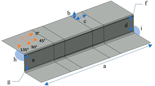
FIGURE 1. Geometry used for forming trials.
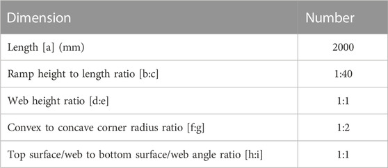
TABLE 1. Geometry dimensions.
The NCF plies were placed on the geometry upper surface and left to drape over the vertical web and rest on the lower surface under its own weight. The plies for each forming trial were ‘fixed’ on the same location on the upper surface using tape to avoid them from slipping down the vertical surface and enable a repeatable preform location per trial. A non-reusable diaphragm was sealed around four raised edges surrounding the geometry. The bagging was sealed to these raised edges to ensure that the order of drape, an influential parameter in resultant preform wrinkling is controlled for each drape trial. Further, a high elongation vacuum bagging film was used to enable stretching over the complex shape and reduce bridging in corners. A cross-section diagram of the tooling and geometry is shown in Figure 2.
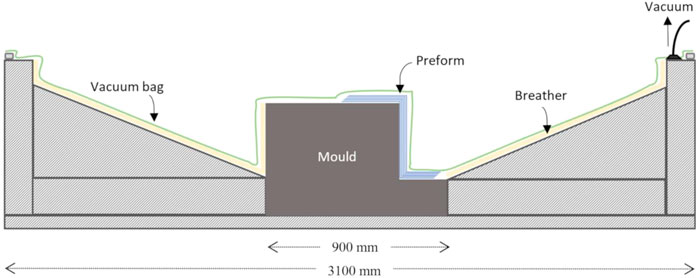
FIGURE 2. Tooling and geometry set up to ensure constant diaphragm kinematics.
During forming, when full vacuum is applied, the diaphragm contacts the top surface first, followed by the male or convex radius and outside edge of the bottom surface. The last surface the diaphragm meets is the female or concave radius. This creates a ‘clamping effect’ on the flange area of the preform where most of the wrinkling was observed. The preform surface was scanned while still under vacuum with a Hexagon Absolute Arm and interrogated for wrinkle dimensions using Polyworks software.
Three carbon fibre NCF orientations were used to create the preforms. The specification of each is shown in Table 2.
TABLE 2. NCF specifications.
Using these NCFs, the matrix of trials seen in Table 3 was carried out. Six plies were placed all at once on the geometry. This number was chosen to show significant wrinkling used to assess the effect of the parameter change. The stitch and loop side of the materials have been shown with the fibre orientation highlighted in red. In the case of unbalanced areal weight NCF formats, the heavier areal weight has been underlined. The placement of veil or binder has been shown through the use of “V” and “B” respectively. Cells have been highlighted to show the change in parameter used as a sensitivity study. This reflects constraints typical to an industrial matrix, far from the idealised one factor at a time matrix of trials. The sensitivity studies on the different parameters were therefore not all available for all three NCF formats.
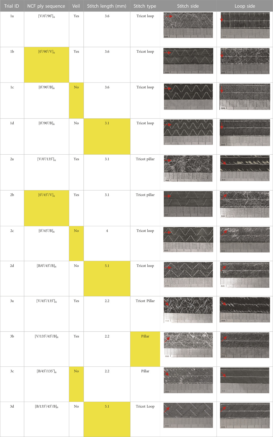
TABLE 3. Matrix of trials.
A number of metrics were considered in order to characterise the resultant wrinkling to allow detailed comparisons.
A qualitative assessment of the shape of the wrinkles was made on the basis of the colour maps generated, see Figure 3.
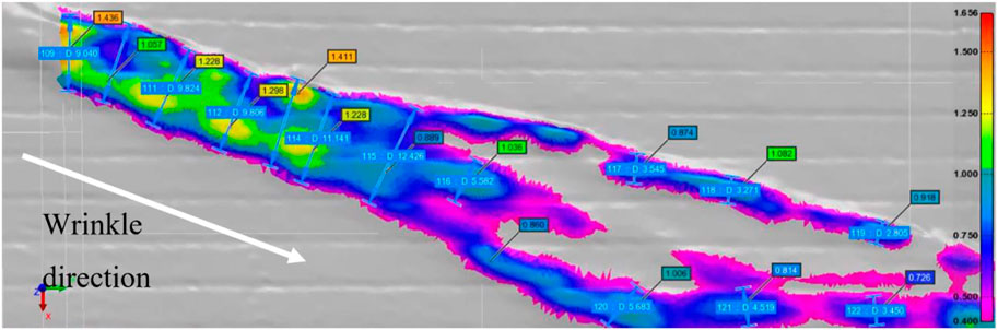
FIGURE 3. Example of sampling points for wrinkle width and height shown along wrinkle length with colour map showing out-of-plane heights.
To capture the size of the wrinkle, three characteristic metrics were considered, including amplitude, wavelength, and aspect ratio. These measures were obtained by sampling the wrinkles along their length, as shown in Figure 3. Wavelength (shown in blue) are sampled perpendicular to the wrinkle direction vector (labelled in white). An aspect ratio is computed at each sampling location. Wrinkle amplitude was measured relative to the upper surface of the outermost ply (coloured in grey in Figure 3). A lower limit of 0.4 mm out-of-plane height was used in all trials to filter out the “noise” of the overall NCF surface (caused by the stitching or tow edges).
The location of the wrinkle within the part geometry was assessed both qualitatively through visual inspection of the colour maps as well as through coupling wrinkle amplitude with one of two axes of the plane on which wrinkles were found.
Wrinkling was only assessed on the outermost ply while the preform was still under maximum vacuum. Wrinkling was observed to propagate through the stack of six plies during removal of the plies from the geometry. However, no assessment was made of these as the plies were not heated or ‘binder activated’ and therefore no longer consolidated to the geometry once vacuum was released to observe the inner plies.
The scanned preform results, labelled by Trial ID, are shown in Figure 4. Colour maps show the distribution of out-of-plane heights along the wrinkle, with the scale adjusted for each NCF orientation for viewing purposes. The lower end value of the scale has been adjusted to filter out the “noise” caused by the texture of the NCF preform (0.4 mm). A front-on view to the geometry web surface is chosen as this was the area where most of the wrinkling occurred. A rosette shows the orientation of the fibres as seen on the web. Vertical lines show the start and end of both left and right ramps on the geometry.
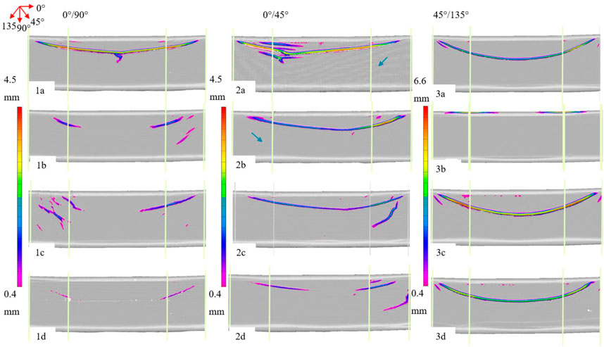
FIGURE 4. Frontal web view of 3D preform scans showing wrinkle height colour maps and location relative to ramps on geometry.
The images show most of the wrinkling initiates on the outside edges of both ramps and descends diagonally down towards the centre plane forming a crescent shape. Not all preforms connect at the centre to form a continuous wrinkle, as seen in most of the 0°/90° trials (1b-d). The 45°/135°‘s on the other hand all seem to show a continuous and symmetric “smile” wrinkle (3a, 3c-d), except for the veiled heavier (areal weight) format (3b). This trial is different in appearance from all others with wrinkling occurring on the upper (convex) radius of the geometry rather than on the web surface. Both wrinkles however are still located around the ramp regions, suggesting it is geometry driven. The distinct wrinkling is likely caused by the combination of veil with pillar stitch pattern, pointing at an interaction between these two parameters.
All wrinkling patterns are approximately symmetric in appearance, though there are differences in overall wrinkle heights between left and right wrinkles, with the 0°/45° layups showing the least symmetry. In fact, the shape of these is seen to change depending on whether the orientation is a 0°/45° or a 0°/135°, as observed when comparing trial 2a to trials 2b-d. Additional shorter wrinkles are also observed in some of these trials.
As well as differences in preform results between NCF orientations, the effect of the NCF architecture is shown. Results show noticeably higher wrinkling on the veiled preforms, especially those with veil applied on the 0° fibres (1a, 2a). For the 45°/135°’s the opposite effect was observed with more noticeable wrinkling on the non-veiled preforms. A higher stitch length on the 0°/45°’s and 45°/135°’s (2d and 3d) showed lower wrinkling whereas on the 0°/90°’s (3c), the effect was the opposite with a slight increase in stitch length (from 3.1 to 3.6) showing higher wrinkling (3c vs. 3d). This shows the importance of tailoring NCF parameters dependent on orientation.
Wrinkle amplitude and wavelength values are shown in Table 4. Results show the highest out-of-plane values for Trials 3b and c, suggesting the combination of pillar stitch pattern on a 45°/135° NCF drives this. Overall results show higher wrinkle amplitude values for veiled materials, with the 45°/135° NCFs showing overall higher wrinkling. The lowest amplitude value (1d) correlated with the smallest visible wrinkling observed in 1d shown in Figure 4. Maximum wrinkle wavelengths on the other hand did not match those with maximum wrinkle amplitudes, with veiled trials (1a, 2a, 2b) showing overall wider wrinkling. The opposite was observed for non-veiled 45°/135°s (3c and 3d). Stitch length had a minimal effect in both wrinkle wavelength and amplitude for 0°/45°s and 45°/135°s, whereas a larger difference in wrinkle wavelength between the 0°/90° trials (1c and d) was observed, with the shorter stitching resulting in lower overall wrinkling. This same trend however was not able to be assessed for 0°/45°s and 45°/135°s as other material parameters may have affected the result (e.g. the change in stitch pattern in the case of the 45°/135°s between 3c and 3d). Higher standard deviation values were observed for wrinkle wavelengths over wrinkle amplitudes. However no clear link is observed between NCF parameters and standard deviation. This points at NCF parameters being sensitive to a number of wrinkle metrics and reinforces the use of several methods, both visual and numerical to characterise them.

TABLE 4. Maximum wrinkle amplitude values (mm).
Discrepancies in maximum and average values for each trial ID are observed in both wrinkle amplitude and wavelength values. Overall, the tabulated results help show the distribution of sample values from the wrinkles shown in the colour maps. Scatter plots for wrinkle amplitude vs. wavelength values for all trials are shown in Figure 5. A linear relationship between amplitude and wavelength is observed in all trials, with amplitude increasing as wavelength increases. This shows wrinkle aspect ratio (ratio of amplitude to wavelength) is specific to the NCF format or trial (1a, 2a, etc). Not all trials however, show a perfectly linear correlation, with some, for example 3c showing a changing aspect ratio value for higher wrinkle values.
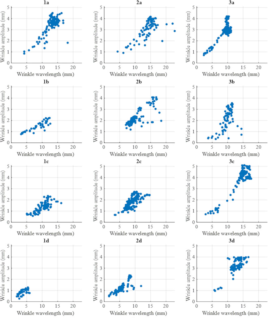
FIGURE 5. Wrinkle amplitude vs. wavelength plots.
Data points were sampled from all wrinkles observed on the geometry web and have not been distinguished for those showing several separate wrinkles. This again shows aspect ratio as a material driven parameter, as data points from different wrinkle instances but for the same NCF material can be best fitted together. In fact, no relationship is observed between number of wrinkles and resultant level of scatter. As the wrinkles were sampled uniformly along their length, shorter or smaller wrinkles contain a smaller number of samples plotted, as is the case for 1d for example where the wrinkling is overall low and the distribution highly clustered. In most cases the scatter increases at higher wrinkle amplitude and wavelength values. The 45°/135°s show an increase in gradient with higher amplitudes for the same wavelength recorded at higher values. The effect of veil on the 0°s for the 0°/90°s shows as a higher aspect ratio (1a vs. 1b and 1c). This effect is not as discernible for the 0°/45°s. Stitch length on the other hand does not seem to have an effect on aspect ratio, but rather on absolute maximum values.
The wrinkle colour maps shown in Figure 4 pointed at asymmetry in both the shape of the wrinkle as well as the distribution of amplitude along the wrinkle. This has been plotted in Figure 6. Wrinkle amplitude values sampled have been shown against their respective location along the length of the web. The area of the ramps is shaded on the graphs. Results show the maximum amplitude values tend to occur on the inner ramp edges, where these meet the flat central plane. Amplitude then decreases in this central plane in the case of continuous wrinkles that join at the centre, or more generally decrease towards the end of the wrinkle. This is also observed for the individual wrinkles surrounding the larger wrinkles (2a, 1c, 2c, 2d) and shows in the form of an upside down “v” shape on the plots. Overall, a sharper increase to the maximum point or “peak” of the wrinkle is observed in the veiled preforms (1a-3b). This is most noticeable in the 45°/135°s where 3c and 3d show flatter peaks. The asymmetry in the 0°/45°s can be observed with one side showing a higher peak amplitude than the other.
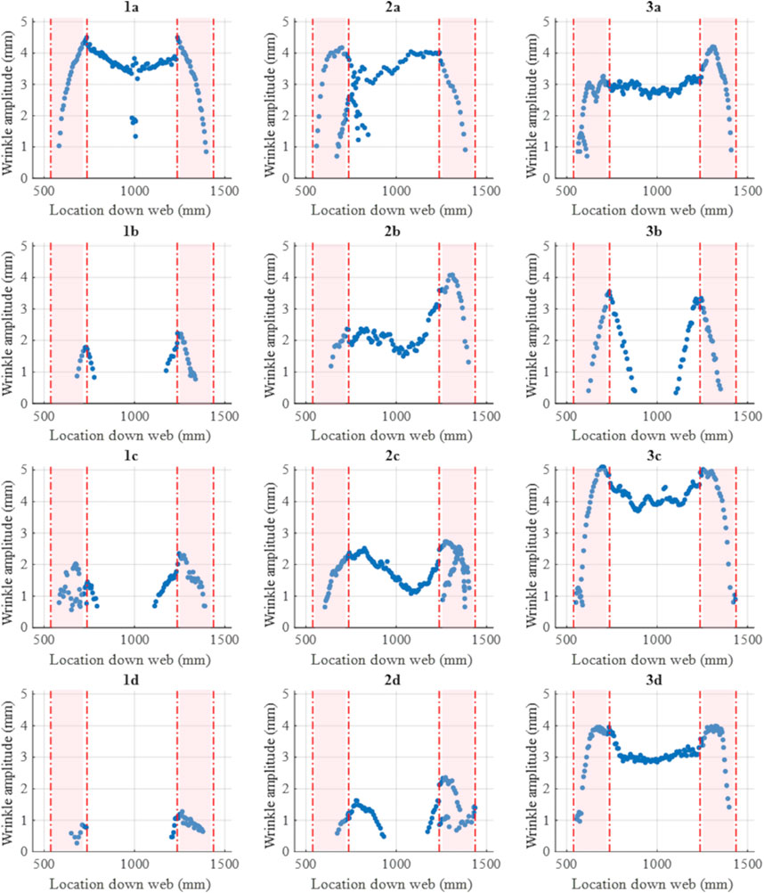
FIGURE 6. Wrinkle amplitude vs. location along web showing location of ramps.
This study has presented a comprehensive matrix of forming trials to show the effect of NCF material architecture on out-of-plane wrinkling. Though the matrix is far from an idealised “one factor at a time” full factorial design, the combined effect of NCF material parameters has been shown where individual parameters could not be isolated. For example, the distinctive corner wrinkling observed in trial 3b was stipulated to be likely due to the combination of veil with pillar stitch pattern. This itself points at a strong interaction between these two parameters. The singular effect of a pillar over a tricot stitch however cannot be isolated due to the likely interaction with other material parameters. Further studies would therefore benefit from a one-factor at a time approach to Design of Experiments. Different methods have also been presented for characterising the resultant wrinkling. This is of relevance as some trends or hypotheses that are visible through some methods are not visible in others. The location of 3b for example, by comparison to all other trials, showed wrinkling in the top radius, rather than on the geometry web. The assessment of the wrinkling can then be based not just on wrinkle dimensions but on whether the location on the structure is critical. Overall, the general similarities in location and shape of the wrinkling point at these being geometry driven. The recess ramp feature causes an excess in fibre length in the centre of the geometry. The diaphragm kinematics (as described in the Methodology) result in this excess occurring between the “clamped” or “tensioned” regions of the preform on the upper and lower surfaces. This leads to the characteristic “smile” wrinkle observed in the centre of the ramps on the flange of the geometry. The reader is referred to the kinematic model of the geometry shown by Jimenez Martin et al. in (Martin et al., 2022a). Sjölander et al. (Hallander et al., 2015), using a similar recess ramp geometry stipulated that the wrinkling was a result of interaction between two layers with specific fibre orientations or due to compression of the entire stack. The differences in wrinkle size (amplitude, wavelength) point at material driven behaviour in forming.
When comparing wrinkle shapes, similarities between trials of the same NCF orientation are observed. The 0°/45°s (2a-d) for example show an asymmetric “smile” wrinkle, i.e. the “trough” of the wrinkle occurs to one side rather than in the centre as is the case for the 45°/135°s. The side (towards left or right ramp) that the trough occurs in depends on whether the NCF is a 0°/45° or a 0°/135°, as seen when comparing 2a to trials 2b-d. This side also shows higher out-of-plane wrinkle values than the longer side of the wrinkle. This is due to an area of the 45° (or 135°) fibres having a free edge at the side of the preform, as shown in Figure 7. The free edge is a result of the sequence of the diaphragm contact points on the geometry, leading to an upper and a lower constrained edge with free edges to the left and right of the geometry. This creates a tension or ‘clamping’ effect across the height of the geometry flange. The area between ‘45 fibre path 1′ and ‘45 fibre path 2′ is fully constrained on both upper and lower edges, whereas the area to the right of ‘45 fibre path 2′ sees a free edge. This phenomenon was shown by Guzman et al. (Guzman-maldonado et al., 2022) in the form of an increase in shear observed in this triangular region of fibres. However, as not enough tension (the tension in this case is provided by the diaphragm) is applied in the direction of the fibres as was stipulated in Guzman’ work, the result instead is higher out-of-plane wrinkling. This may also explain why the amplitude profile for the 45°/135°’s over the length of the geometry decreases in the centre between the two ramps, as the fibres are all constrained in this region (by the two constrained edges shown in Figure 4) and therefore tensioned more than those with a free edge. The tension results in lower out-of-plane wrinkling.
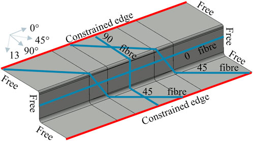
FIGURE 7. Diagram of fibre paths constrained at top and bottom edges of the geometry, and free at either side, left and right.
Preforms with added veil showed overall wider amplitude wrinkling and higher thickness due to the added weight of the veil. The higher amplitude may be due to the additional inter-ply friction created by the veil, as pointed out by Hallander et al. in their study on prepreg (Hallander et al., 2013). The addition of veil also contributes to a higher overall areal weight, likely leading to an increase in bending stiffness, this in turn may contribute to the resultant higher level of wrinkling, both in amplitude and in number of wrinkles. In fact, Boisse et al. (Boisse et al., 2011) showed the direct effect of bending stiffness on number of wrinkles: a higher bending stiffness led to less wrinkles and hence more shearing in the material.
As the veiled material formats showed overall less distributed separate wrinkling, this suggests the addition of veil on NCFs significantly increases the bending stiffness properties. The orientation on which veil is applied was also shown to be an important parameter for unbalanced NCF formats (0°/90° and 0°/45°). With both formats weighted towards the 0° fibres, a difference in resultant wrinkling was observed dependent on which orientation the veil was applied on. Results showed overall higher wrinkling for formats with veil applied on the 0° fibres, showing a higher areal weight exacerbates the influence of veil on the preform. The addition of veil on the 45°/135°s however did not show observable differences in number of wrinkling and showed an opposite effect to the 0°/90°s and 0°/45°s in terms of wrinkle amplitude: veiled 45°/135°s showing lower wrinkle amplitude, whilst veiled 0°/90°s and 0°/45°s leading to higher wrinkle amplitudes. This highlights the complex interaction between NCF parameters and the need to tailor them dependent on orientation.
This study has presented a matrix of trials realistic of an industrial campaign, carried out on a much larger scale geometry with representative features for aerostructures than is currently available in the literature. Results show that whereas location and shape of the wrinkling are driven by geometry, wrinkle size and its defining parameters (amplitude, wavelength, aspect ratio) are driven by the parameters defining NCF architecture. The interaction between these leads to complex wrinkling, characterised both numerically and graphically. The key trends extracted include:
• location and shape of the wrinkling are mainly geometry driven whereas wrinkle amplitude and width are mainly material driven
• non-orthogonal 0°/45° NCF’s show asymmetric wrinkling due to the difference in constrained edges seen by the two fibre orientations
• veiled NCFs showed overall higher wrinkling, though the effect changes dependent on other material variables such as stitch and orientation
• 45°/135°s showed overall higher wrinkling over the 0°/90° and 0°/45° formats.
Conflicting trends observed previously in the literature, for example with regards to veil, have also been shown to differ dependent on which NCF architecture variables these are combined with, once again highlighting the challenge of identifying single key parameters to formability. Trends extracted also differ between wrinkle characterisation methods chosen, showing the complexity in attempting to use these as a single metric for formability. The study therefore shows the importance of using several characterisation methods and not reducing wrinkling definitions to a single data point or set. Overall, the study has showcased the sensitivity of resultant preform wrinkling to NCF architecture and the importance of wrinkle characterisation methods to analyse the sensitivity. The results from the study may impact future process modelling approaches to defect prediction, for example through highlighting key parameters that may influence the model result.
The datasets presented in this article are not readily available because the raw data required to reproduce these findings are subject to industrial confidentiality. Requests to access the datasets should be directed to James Kratz, amFtZXMua3JhdHpAYnJpc3RvbC5hYy51aw==.
CJ: Conceptualization, Methodology, Validation, Formal analysis, Investigation, Data Curation, Writing—Original Draft, Visualization. VM: Conceptualization, Writing—Review and Editing, Supervision. TM: Conceptualization, Resources, Writing—Review and Editing, Supervision, Funding acquisition. JK: Conceptualization, Writing—Review and Editing, Supervision, Funding acquisition.
The research presented was supported by the Airbus, part funded by the UK’s Aerospace Technology Institute, and the EPSRC through the Centre for Doctoral Training in Composites Manufacture (EP/L015102/1) and the Programme Grant “Certification for Design—Reshaping the Testing Pyramid” (CerTest, EP/S017038/1). The support received is gratefully acknowledged.
Authors CJ and TM were employed by the company Airbus UK.
The remaining authors declare that the research was conducted in the absence of any commercial or financial relationships that could be construed as a potential conflict of interest.
All claims expressed in this article are solely those of the authors and do not necessarily represent those of their affiliated organizations, or those of the publisher, the editors and the reviewers. Any product that may be evaluated in this article, or claim that may be made by its manufacturer, is not guaranteed or endorsed by the publisher.
Bardl, G., Nocke, A., Hübner, M., Gereke, T., Pooch, M., Schulze, M., et al. (2018). Analysis of the 3D draping behavior of carbon fi ber non-crimp fabrics with eddy current technique. Compos Part B [Internet] 132, 49–60. doi:10.1016/j.compositesb.2017.08.007
Boisse, P., Hamila, N., Vidal-Sallé, E., and Dumont, F. (2011). Simulation of wrinkling during textile composite reinforcement forming. Influence of tensile, in-plane shear and bending stiffnesses. Compos Sci. Technol. [Internet] 71 (5), 683–692. doi:10.1016/j.compscitech.2011.01.011
Chen, S., Joesbury, A. M., Yu, F., Harper, L. T., and Warrior, N. A. (2021). Optimisation of intra-ply stitch removal for improved formability of biaxial non-crimp fabrics. Compos Part B Eng. 229, 109464. doi:10.1016/j.compositesb.2021.109464
Guzman-maldonado, E., Bel, S., Bloom, D., Fideu, P., and Boisse, P. (2022). Materials & Design Experimental and numerical analyses of the mechanical behavior during draping of non-orthogonal bi-axial non-crimp fabric composite reinforcements. Mater Des. [Internet] 218, 110682. doi:10.1016/j.matdes.2022.110682
Guzman-Maldonado, E., Wang, P., Hamila, N., and Boisse, P. (2019). Experimental and numerical analysis of wrinkling during forming of multi-layered textile composites. Compos Struct. [Internet 208, 208–223. doi:10.1016/j.compstruct.2018.10.018
Hallander, P., Akermo, M., Mattei, C., Petersson, M., and Nyman, T. (2013). Composites: Part A an experimental study of mechanisms behind wrinkle development during forming of composite laminates. Compos Part A [Internet] 50, 54–64. doi:10.1016/j.compositesa.2013.03.013
Hallander, P., Sjölander, J., and Åkermo, M. (2015). Forming induced wrinkling of composite laminates with mixed ply material properties; an experimental study. Compos Part A Appl. Sci. Manuf. [Internet] 78, 234–245. :. doi:10.1016/j.compositesa.2015.08.025
Hallander, P., Sjölander, J., Petersson, M., and Åkermo, M. (2016). Interface manipulation towards wrinkle-free forming of stacked UD prepreg layers. Compos Part A Appl. Sci. Manuf. [Internet] 90, 340–348. doi:10.1016/j.compositesa.2016.07.013
Heieck, F. (2015). Binder application methods for textile preforming processes. APrIL - Adv. Preform Manuf. Industrial LCM-Processes, 1–16.
Lomov, S. (2016). Non-crimp fabric composites: Manufacturing, properties and applications. Cambridge: Woodhead Publishing Series in Composites Science and Engineering.
Martin, C. J., Maes, V., Mcmahon, T., and Kratz, J. (2022). Large scale forming of non-crimp fabrics for aerostructures. Key Eng. Mat. 926, 1387–1398. doi:10.4028/p-809h64
Martin, C. J., Maes, V. K., Mcmahon, T., and Kratz, J. (2022). The role of bias extension testing to guide forming of non-crimp fabrics. Front. Mater. 9, 1–13. doi:10.3389/fmats.2022.825830
Nosrat, F., Gereke, T., and Cherif, C. (2016). Composites: Part A analyses of interaction mechanisms during forming of multilayer carbon woven fabrics for composite applications. Compos PART A [Internet] 84, 406–416. :. doi:10.1016/j.compositesa.2016.02.023
Thompson, A. J., Said, B. E., Belnoue, J. P., and Hallett, S. R. (2018). Modelling process induced deformations in 0/90 non-crimp fabrics at the meso-scale. Compos Sci. Technol. [Internet] 168, 104–110. doi:10.1016/j.compscitech.2018.08.029
Turk, M. A., Vermes, B., Thompson, A. J., Belnoue, J. P-H., Hallett, S. R., and Ivanov, D. S. (2019). Mitigating forming defects by local modification of dry preforms. Compos Part A Appl. Sci. Manuf. 128, 105643. doi:10.1016/j.compositesa.2019.105643
Keywords: non-crimp fabric, forming, dry fibre process, wrinkles, characterisation
Citation: Jimenez Martin C, Maes VK, McMahon T and Kratz J (2023) Influence of NCF architecture on the morphology of forming induced wrinkling. Front. Mater. 10:1126933. doi: 10.3389/fmats.2023.1126933
Received: 18 December 2022; Accepted: 31 January 2023;
Published: 17 February 2023.
Edited by:
Veronique Michaud, Swiss Federal Institute of Technology Lausanne, SwitzerlandReviewed by:
Naim Naouar, Institut National des Sciences Appliquées de Lyon (INSA Lyon), FranceCopyright © 2023 Jimenez Martin, Maes, McMahon and Kratz. This is an open-access article distributed under the terms of the Creative Commons Attribution License (CC BY). The use, distribution or reproduction in other forums is permitted, provided the original author(s) and the copyright owner(s) are credited and that the original publication in this journal is cited, in accordance with accepted academic practice. No use, distribution or reproduction is permitted which does not comply with these terms.
*Correspondence: James Kratz, amFtZXMua3JhdHpAYnJpc3RvbC5hYy51aw==
Disclaimer: All claims expressed in this article are solely those of the authors and do not necessarily represent those of their affiliated organizations, or those of the publisher, the editors and the reviewers. Any product that may be evaluated in this article or claim that may be made by its manufacturer is not guaranteed or endorsed by the publisher.
Research integrity at Frontiers
Learn more about the work of our research integrity team to safeguard the quality of each article we publish.