 Zhenwen Sun
 Weiping Huang1
 Hailong Lu
 Yuanchao Yin
95% of researchers rate our articles as excellent or good
Learn more about the work of our research integrity team to safeguard the quality of each article we publish.
Find out more
ORIGINAL RESEARCH article
Front. Mater. , 13 January 2023
Sec. Mechanics of Materials
Volume 10 - 2023 | https://doi.org/10.3389/fmats.2023.1118046
This article is part of the Research Topic Design and Mechanical Failure of Deep-Sea Pressure Structures View all 6 articles
Fibre reinforced flexible pipes are subjected to radial compression loads caused by the tensioner during pipe laying, which may lead to excessive deformation or even damage of the pipe. In this study, the mechanical characteristics of a glass fibre reinforced unbonded flexible pipe are investigated under radial compression loading. In the theoretical analysis, the hoop reinforcement layer of the pipe is considered equivalent to an orthotropic circular tube. An analytical equation for calculating the radial stiffness of the circular tube per unit length is then derived based on the classical elastic theory of the ring. Radial compression tests are carried out with a universal testing machine and displacement loading within the elastic deformation range is applied to two 500 mm long samples. A 3D numerical model is established to simulate the compression process of the flexible pipe, through which the distribution characteristics of the displacement, strain and stress of the hoop reinforcement layer are also obtained. The load-displacement curves obtained from the tests and numerical model are linearly fitted to calculate the radial stiffness of the pipe. The radial stiffness obtained by the numerical model is very close to that obtained by the analytical method. However, owing to factors such as material defects and initial ovality, the radial stiffness measured experimentally is lower than the analytical result.
Fibre reinforced flexible pipes are a new type of offshore flexible pipe. They usually consist of reinforcement layers and polymer layers, similar to typical flexible pipes (API SPEC 17J, 2014). The hoop reinforcement layer serves to resist external pressure, whereas the tensile reinforcement layers mainly provide axial stiffness. Fibre reinforced flexible pipes, such as the Technip (Do and Lambert, 2012) and Deepflex products (Bryant et al., 2007) replace metal reinforcement layers with composite reinforcement layers, which results in a lighter weight, better corrosion resistance, and improved fatigue performance compared with typical flexible pipes.
Fibre reinforced flexible pipes may be subjected to uniform loads caused by hydrostatic pressure during operation and concentrated loads caused by the tensioner during laying. As a result, buckling and crushing damage are the most common failure modes of flexible pipes (API RP 17B, 2014). To avoid excessive deformation and failure, the radial stiffness and ultimate failure load of flexible pipes should be calculated. The classical ring elastic theory (Timoshenko and Gere, 1961) is used to derive the calculation formula for the radial stiffness by equating the carcass layer to the homogeneous ring with a rectangular section and ignoring the contribution of all other layers to the radial resistance. The main difference between theoretical methods is the determination of the thickness of the equivalent ring. These methods mainly include the section area equivalent method (Zhang et al., 2003), unit area bending stiffness equivalent method (de Sousa et al., 2001) and unit length bending stiffness equivalent method (Martins et al., 2003). The finite element method can be used to establish 3D models considering the detailed geometry and non-linear factors such as the material plasticity and contact, thus providing more accurate solutions for the stress, displacement and other variables and improving the convenience of parametric sensitivity analyses. Prototype tests can be used to observe the whole deformation and failure process of flexible pipes directly to verify the analytical and numerical results.
Malcorps and Felix-Henry (2008) demonstrated experimentally that the deformation of a flexible pipe under radial crushing is a gradual process. Pesce et al. (2010) obtained the real yield stress of the carcass layer through a 3D numerical model and presented a sensitivity analysis regarding the ovality. The effects of geometric non-linearity and material plasticity were considered in a subsequent numerical analysis (Franzini et al., 2011). Optical measurements and image processing were used in radial crushing tests (Fujarra et al., 2010) to accurately capture the displacement behaviour of the carcass layer, thus providing a comprehensive understanding of the deformation behaviour of the pipe. A non-linear analytical model of the equivalent ring considering the combined action of the carcass layer and pressure armour (Pesce et al., 2012) was also extended to consider the crushing problem of flexible pipes. Santos et al. (2015) proposed a 2D numerical model to predict the stress and strain fields of an umbilical cable under a radial crushing load, while the displacement field was assessed using a high-resolution digital image correlation (DIC) system (Santos et al., 2016). Mendonça and Martins (2016; 2017) studied the stress and displacement of the carcass layer and pressure armour with parametric variations using the finite element method. Tang et al. (2016) proposed the strain energy equivalent method for the carcass layer and verified it through a finite element model and radial compression tests. Caleyron et al. (2017) introduced collapse tests of flexible pipes conducted by Technip; the corresponding calculations were performed using finite element models considering the ovality, plasticity, and manufacturing residual stress. Ren et al. (2019) modified the bending stiffness equivalent method for the carcass layer by introducing the geometric coefficient g, which further improved the accuracy of the solution.
Almeida et al. (2017) established a damage model that was connected to finite element software through the UMAT subroutine to evaluate the effect of the material stacking sequence on the failure of a composite pipe under radial crushing loads. Stabla et al. (2022) demonstrated that the winding angle and mosaic pattern had a significant influence on the radial compression response of a filament-wound pipe using both experimental and numerical approaches. Lisbôa et al. (2022) developed a finite element model updating routine to verify the influence of the winding pattern on the damage evolution parameters of wound cylinders. A numerical simulation of a composite pipe under tensile and radial compressive loads was conducted using the LS-DYNA finite element software (Abdallah and Braimah, 2022) to evaluate the effects of the winding angle and ply sequence on the pipe stiffness and failure mode.
A glass fibre reinforced unbonded flexible pipe with an inner diameter of 6-inch and nine layers is investigated in this study. The pipe consists of liner, inner hoop layer, two inner tensile reinforcement layers, hoop reinforcement layer, membrane, two outer tensile reinforcement layers and outer sheath, as shown in Figure 1. The tensile reinforcement and hoop reinforcement layers are all spiral structures wound in a single direction using a glass fibre wet winding process. The inner hoop layer is a circular structure formed by curing after cross winding of the glass fibre. The liner, membrane and outer sheath are formed by extrusion moulding of polyethylene. The hoop reinforcement layer has a large winding angle and the largest thickness of all layers, and thus it has the greatest contribution to the radial resistance.
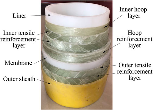
FIGURE 1. Fibre reinforced unbonded flexible pipe with an inner diameter of 6-inch.
To avoid excessive deformation or damage of the fibre reinforced flexible pipe caused by the tensioner, the behaviour under radial compression should be analysed, particularly the most dangerous two-point loading condition. The radial stiffness of the fibre reinforced flexible pipe under a symmetrical radial compression load is obtained using analytical method, tests and finite element model in this study, and the results of different methods are compared. The displacement, strain, and stress distribution characteristics of the hoop reinforcement layer are also discussed.
According to the classical elastic theory (Timoshenko and Gere, 1961), the instability process of a ring can be regarded as a bending problem of a circular bar. It is assumed that the ring has only a small deformation in the radial direction, and the tangential deformation and higher-order small quantities can be ignored. Thus, the deflection differential equation of the circular bar can be given as follows:
where
The ring under a symmetrical concentrated load is shown in Figure 2. The bending moment at any section,
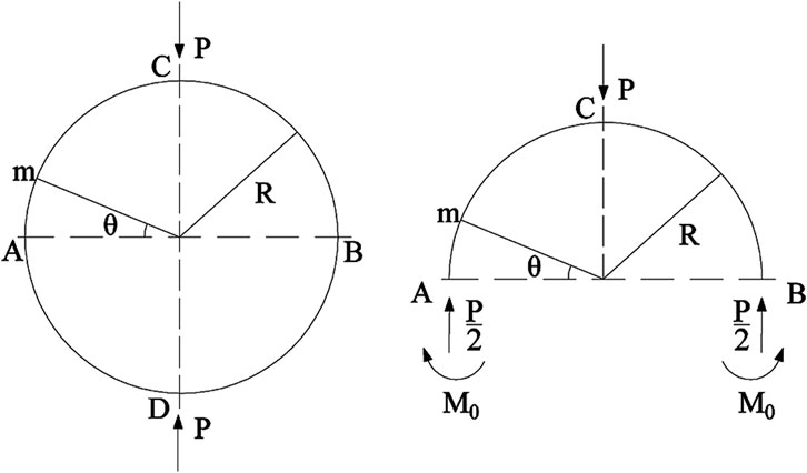
FIGURE 2. Ring under a symmetrical radial compression load.
Substituting Eq. 2 into Eq. 1 yields the general solution of the equation as follows:
According to the Castigliano theorem, the partial derivative of the ring strain energy,
Substituting Eq. 2 into Eq. 4 and integrating gives the bending moment as follows:
Substituting Eq. 5 into Eq. 3 yields the deflection of the ring as follows:
For a uniform circular tube of infinite length, the deflection differential equation similar to Eq. 1 can be obtained by extracting a ring of unit length along the axial direction of the tube. The difference is that the ring is a part of the tube, and its rectangular section will not deform when the ring is bent under axial stress. Then, the elastic modulus,
where
The corresponding displacement can be calculated as follows:
When
The radial compression stiffness per unit length of the ring within the range of elastic deformation is given as follows:
The equivalent thickness of the tube can be estimated using the section area equivalent method (Zhang et al., 2003). For the hoop reinforcement layer composed of two spiral belts, the equation can be given as follows:
where
For the radial compression tests, a sample of the fibre reinforced flexible pipe containing all layers should be used, because it is difficult to obtain a separate sample of the hoop reinforcement layer under the condition where multiple inner and outer structural layers exist. Unlike the interlocking structure, the hoop reinforcement layer is a spiral-wound structure that lacks sufficient axial restraint. If the radial compression load acts on the hoop reinforcement layer directly, the spiral belts will be unable to maintain the original winding shape and will become disordered. The hoop reinforcement layer cannot play full role in radial resistance in this condition, which may lead to a large deviation in the test results.
Two 500 mm long samples of fibre reinforced flexible pipe with an inner diameter of 150 mm were extracted for the test. The main geometric parameters and material of each layer of the sample are respectively listed in Tables 1, 2.
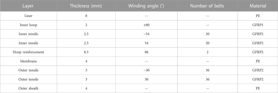
TABLE 1. Geometric parameters and material of each layer.
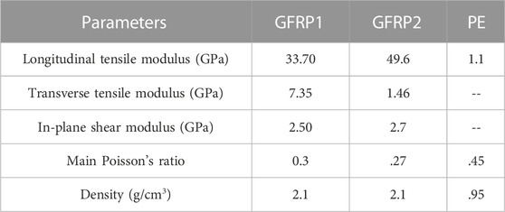
TABLE 2. Parameters of materials.
The primary equipment for the test was a computer-controlled electro-hydraulic servo universal testing machine, as shown in Figure 3. The sample was placed at the centre of the rigid platform, which was completely fixed to the testing machine to ensure that there was no vertical rigid body displacement. The upper steel plate had dimensions of 500 × 400 mm, and the axial direction of the sample was aligned with the long side of the steel plate to ensure uniform radial compression of the sample. The steel plate was connected to an actuator, and the radial compression load was applied to the sample by controlling the vertical displacement. To avoid the influence of the inertial force, the loading rate of the steel plate should not be too large. In addition, the total displacement of the steel plate should be controlled within a certain range to maintain the sample in the elastic deformation range.
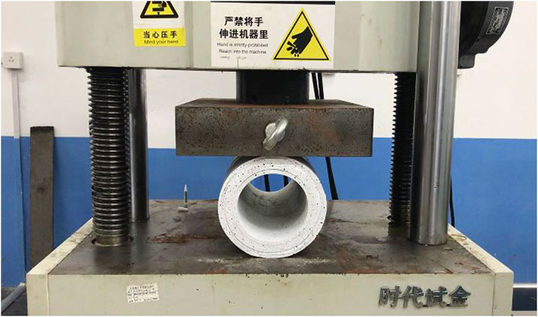
FIGURE 3. Sample and testing machine for the radial compression tests.
Each loading process in the tests lasted for 1.5 min at a speed of 11 mm/min. During the test, the time history curves of the vertical displacement and reaction force of the upper steel plate were output by the displacement sensor installed on the testing machine and the force sensor installed on the actuator, respectively. Then, the radial stiffness of the samples could be obtained from the load-displacement curves.
Using the ABAQUS finite element software, a 3D numerical model of the fibre reinforced flexible pipe and the upper and lower steel plates was established to simulate the radial compression process of the universal testing machine. The local coordinate systems were established for material orientations of all fibre reinforced layers, wherein direction 1 referred to the fibre direction, direction 2 referred to the transverse direction, and direction 3 referred to the thickness direction, thus the output strain and stress followed the direction of local coordinates. The steel plates were defined as rigid bodies, and reference points RP1 and RP2 were located at the centre point of the upper surface of the upper plate and centre point of the lower surface of the lower plate, respectively. Kinematic coupling constraints were established between the two reference points and their corresponding surfaces, and the boundary conditions could then be added through the reference points. Considering the loading condition, all of the degrees of freedom of the RP2 and all of the degrees of freedom except U2 of the RP1 were constrained. The contacts between the pipe and the plates and those between the adjacent layers of the pipe were all defined as general contact. The tangential behaviour was defined using a penalty method based on the Coulomb friction model while the normal behaviour was set as a hard contact. According to the results of friction tests, the friction factor between composite layers was set as .18 while that between composite layer and PE layer was set as .08.
Structured mesh was selected for the cylindrical layers and swept mesh along the helix direction was employed for the spiral layers. After the mesh convergence analysis, the global mesh size was set as 5 mm. The element number along the thickness direction of the hoop reinforcement layer was set as 4. The outer sheath was divided into 83 elements along the axial direction and 116 elements along the circumferential direction. To avoid the influence of excessive deformation of elements on the analysis, Eight-node brick element with reduced integration (C3D8R) were adopted for all parts of the model. The whole model included 164,796 elements and 300,140 nodes, as shown in Figure 4.
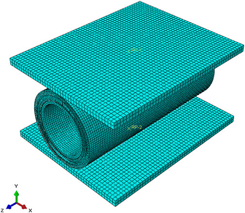
FIGURE 4. 3D finite element model of the fibre reinforced flexible pipe and steel plates.
ABAQUS/Explicit solver was employed for the quasi-static analysis to prevent the convergence problem of the calculation because the model contains non-linear factors such as complex contact. The loading time was set to .1 s. A displacement of −16.5 mm was applied along the U2 direction through RP1. Smooth step was used to control the loading rate and energy curves were monitored to control the inertial effect, thus the accuracy of the calculation can be guaranteed.
The time history curves (Figure 5) of the total internal energy (ALLIE), elastic strain energy (ALLSE), artificial strain energy (ALLAE) and kinetic energy(ALLKE) of the pipe and elastic strain energy of the hoop reinforcement layer (ALLSE-L5) during the loading process were extracted from the finite element results. As shown in Figure 5, the internal energy curve remains relatively smooth without obvious fluctuations throughout the loading process. The kinetic energy remains low and the ratio of kinetic energy to internal energy is only approximately 6.8% at .05 s, which confirms that the quasi-static condition is satisfied in the loading process. The ratio of artificial strain energy to internal energy is approximately 3.3% at .1 s, which indicates that the hourglass problem has little influence. The proportion of elastic strain energy to internal energy is approximately 96.7%, indicating that almost all of the work performed by the external force is converted into elastic deformation of the pipe. The elastic strain energy of the hoop reinforcement layer accounts for 92.3% of the total strain energy, which demonstrates that the hoop reinforcement layer contributes most of the radial stiffness of the pipe.
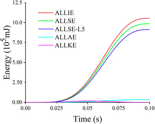
FIGURE 5. Energy time history curves of the fibre reinforced flexible pipe.
When the loading process of the test is completed, the sample shows a certain amount of elliptical deformation (Figure 6A). Similar deformation can also be seen in the finite element analysis results (Figure 6B).
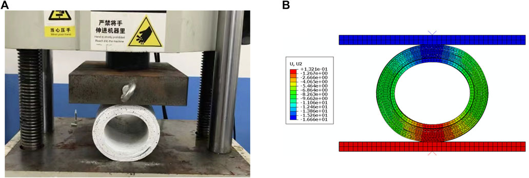
FIGURE 6. Deformation of the fibre reinforced flexible pipe. (A) Experimental result, (B) Numerical result.
The displacement contour images of the hoop reinforcement layer are shown in Figure 7. The points with the maximum horizontal displacement (6.59 mm) are located on the left and right sides of the section, and thus the diameter of hoop reinforcement layer in the horizontal direction increases by 13.18 mm. The points with the maximum vertical displacement (16.19 mm) are located on the upper side of the section. Owing to the elastic deformation of the outer layers caused by compression load, the maximum vertical displacement is slightly less than that of the upper plate (16.5 mm). For the same reason, the points located on the lower side of the section still remain a displacement of .34 mm although the lower plate is constrained in vertical direction. As a result, the diameter of hoop reinforcement layer in the vertical direction decreases by 15.86 mm.
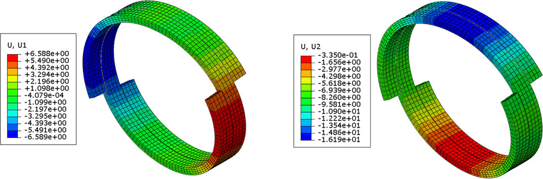
FIGURE 7. Displacement contour images of the hoop reinforcement layer. (A) Horizontal displacement, (B) Vertical displacement.
The vertical displacement and vertical reaction force obtained by different methods were extracted to acquire the load-displacement scatter plot (Figure 8). The results show that with the displacement increased from zero to 16.5 mm gradually, the reaction force obtained by the finite element model, test 1, test 2 and Eq. 10 increased from zero to 126.88kN, 107.41kN, 102.55kN, and 116.53kN, respectively. The relationship between the load and displacement is approximately linear, thus the radial stiffness per unit length of the pipe can be obtained through the result of linear fitting (the line in Figure 8) and further calculation. The radial stiffness values of the pipe and errors obtained by different methods are summarised in Table 3.
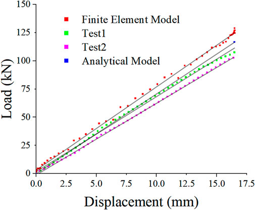
FIGURE 8. Load-displacement curves obtained by different methods.

TABLE 3. Radial stiffness of the fibre reinforced flexible pipe calculated using different methods.
As indicated in Table 3, the radial stiffness obtained by analytical model and numerical model are reasonable. The analytical result considering only the hoop reinforcement layer is 95.7% of the finite element result considering all layers of the pipe, which is similar to the conclusion that the elastic strain energy of the hoop reinforcement layer accounts for 92.3% of the total strain energy. The radial stiffness of the numerical result and the analytical result are 13.5% and 8.7% more than the experimental result respectively because the actual production process of the pipe is not ideal. Material defects such as an insufficient fibre volume ratio, uneven distribution of the fibres, uneven winding tension, uneven dipping, and excessive porosity will cause the actual elastic constant of the glass fibre reinforced belts to be lower than that measured by the material test, which will lead to a decrease in the radial resistance of the pipe. In addition, structural defects such as initial ovality are inevitable in the manufacturing process, which further reduces the radial stiffness of the pipe.
The accuracy of the finite element model was verified by comparing the radial stiffness results with those obtained in the tests and with the analytical equations in the previous section. The distributions of strain and stress in the fibre direction of the hoop reinforcement layer under a radial compression load are discussed in this section because the strain and stress in the primary direction of materials are closely related to the failure of anisotropic materials. As the load applied on the pipe model was uniform along the axis direction, one pitch length of the spiral belt in the middle section of the hoop reinforcement layer was extracted for analysis.
Eight points were selected along the circumferential direction of the hoop reinforcement layer, as shown in Figure 9. Regions with large tensile strains in the fibre direction include the 0° position (P1) and 180° position (P3) on the inner surface of the layer as well as the 90° position (P6) and 270° position (P8) on the outer surface of the layer. Regions with large compressive stresses in the fibre direction include the 0° position (P5) and 180° position (P7) on the outer surface of the layer as well as the 90° position (P6) and 270° position (P8) on the inner surface of the layer. The output curves of strain (fibre direction) and displacement (upper plate) at different points (Figure 10) show that the strains are consistent if two points are symmetrical about the horizontal or vertical axis, confirming the uniformity of the load applied to the pipe. When loading was completed, the average strains of P1 and P3, P5 and P7, P6 and P8, and P2 and P4 are .97%, −.97%, .56%, and −.61%, respectively. The 0° and 180° positions are directly subjected to the radial compression load, leading to a greater strain than that of the 90° and 270° positions.
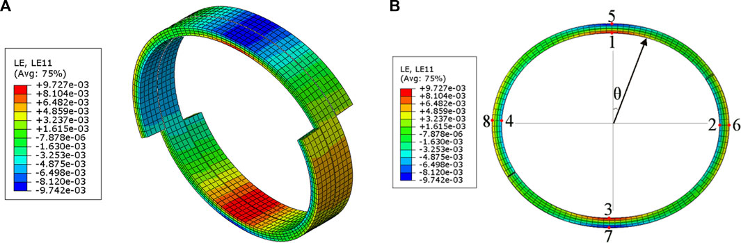
FIGURE 9. Contour images of the fibre-direction strain of the hoop reinforcement layer. (A) ISO view, (B) Front view.
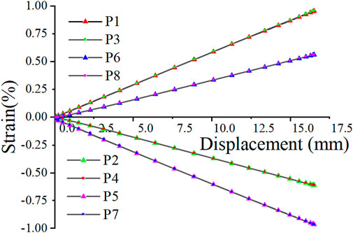
FIGURE 10. Strain-displacement curves of points on the hoop reinforcement layer.
As shown in Figures 11A,B, the stress distribution characteristics of the hoop reinforcement layer are consistent with the strain distribution characteristics shown in Figure 9. The output curves of stress (fibre direction) and displacement (upper plate) at different points (Figure 12) show that the average stresses at P1 and P3, P5 and P7, P6 and P8, and P2 and P4 are 476.3 MPa, −473.6 MPa, 281.8 MPa, and - 304.9 MPa, respectively, when loading was completed. These results indicate that the stresses at the 0° and 180° positions are significantly higher than that of the 90° and 270° positions. For glass fibre reinforced plastics, the tensile strength in the fibre direction is usually higher than the compressive strength in the same direction. It can be inferred that with a further increase in the radial compression load, the regions near P5 and P7 may reach the compressive strength of the material, leading to subsequent structural damage. Therefore, it is necessary to focus on monitoring the contact position between the pipe and the tensioner when fibre reinforced flexible pipe is laid into the water.
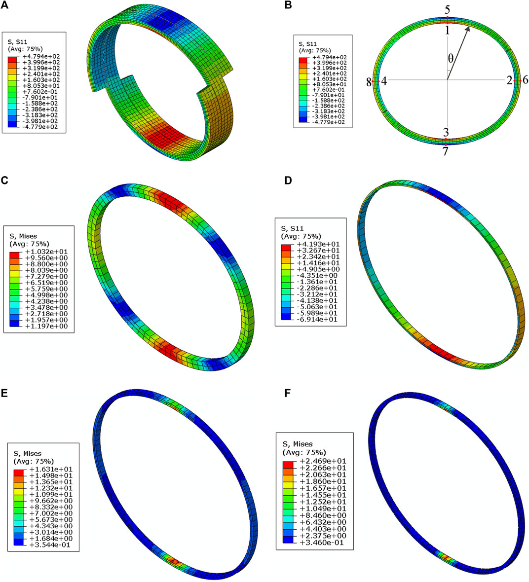
FIGURE 11. Contour images of the stress distribution of the pipe layers (A) ISO view of fibre-direction stress of the hoop reinforcement layer. (B) Front view of fibre-direction stress of the hoop reinforcement layer. (C) Mises stress of the liner. (D) Fibre-direction stress of the inner hoop layer. (E) Mises stress of the membrane. (F) Mises stress of the outer sheath.
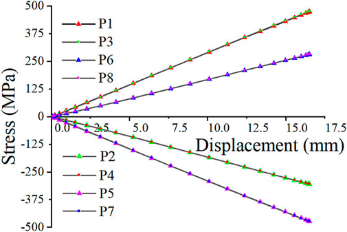
FIGURE 12. Stress-displacement curves of points on the hoop reinforcement layer.
Except for the hoop reinforcement layers, other layers also contribute to the radial stiffness. The contributions of cylinder layers are greater than those of helical layers, thus the middle sections of the liner, the inner hoop layer, the membrane and the outer sheath were extracted for stress analysis. To acquire the distribution characteristics of stress, the mises stress of isotropic layers and fibre-direction stress of inner hoop layers were output, respectively. As shown in Figures 11C–F, the stress at the 0° and 180° positions of the sections are significantly higher than that of other positions, which is similar to that of hoop reinforcement layer. The maximum mises stress of the liner, the membrane and the outer sheath are 10.32, 16.31, and 24.69 MPa, respectively. The maximum tensile stress and compressive stress of the inner hoop layer are 41.93 and 69.14 MPa, respectively. As a conclusion, the maximum stresses in the cylinder layers are much less than those in the hoop reinforcement layer, which identified the leading role of hoop reinforcement layer in radial resistance.
The mechanical characteristics of fibre reinforced flexible pipe under a symmetrical radial compression load were investigated in this study. An analytical equation for calculating the radial stiffness of orthotropic circular tubes were derived. Radial compression tests of two samples of fibre reinforced flexible pipes were performed. A 3D numerical model was established to simulate the radial compression process of the pipe. The following conclusions were drawn.
1) The radial stiffness per unit length obtained by the analytical method and finite element model are 8.7% and 13.5% more than that obtained by the tests, respectively, which indicate that the analytical model and numerical model can give reasonable estimations for the radial stiffness of the fibre reinforced flexible pipe.
2) The maximum strain and stress are located at the 0° and 180° positions of the inner and outer surfaces of the hoop reinforcement layer, which are greater than those of other layers. So the stress at those two positions may reach the compressive strength first.
Nevertheless, the analytical model and numerical model proposed in this study are only applicable in the range of elastic deformation. The strength of the materials and the failure mode of the pipe under radial compression load should be taken into account in further research.
The datasets presented in this article are not readily available because it also forms part of an ongoing study. Requests to access the datasets should be directed to Zhenwen Sun, c3p3bXNueHpAMTYzLmNvbQ==.
ZS: Conceptualization, Methodology, Experiment, Data curation Investigation, Formal analysis, Writing original draft. WH: Investigation, Writing—review and editing, Supervision. HL: Investigation, Writing—review and editing, Supervision. JY: Investigation, Writing—review and editing, Supervision. YY: Experiment. YB: Experiment.
Financial support for this research was provided by the National Key R&D Program of China (2021YFA1003501) the National Natural Science Foundation of China (Nos. U1906233, 11732004, 52201312), the Key R&D Program of Shandong Province (2019JZZY010801).
The authors declare that the research was conducted in the absence of any commercial or financial relationships that could be construed as a potential conflict of interest.
All claims expressed in this article are solely those of the authors and do not necessarily represent those of their affiliated organizations, or those of the publisher, the editors and the reviewers. Any product that may be evaluated in this article, or claim that may be made by its manufacturer, is not guaranteed or endorsed by the publisher.
Abdallah, M. H., and Braimah, A. (2022). Numerical design optimization of the fiber orientation of glass/phenolic composite tubes based on tensile and radial compression tests. J. Com. Str. 280, 114898. doi:10.1016/j.compstruct.2021.114898
Almeida, J. H. S., Ribeiro, M. L., Tita, V., and Amico, S. C. (2017). Damage modeling for carbon fiber/epoxy filament wound composite tubes under radial compression. J. Com. Str. 160, 204–210. doi:10.1016/j.compstruct.2016.10.036
API RP 17B (2014). Recommend practice for flexible pipe. Washington DC: American Petroleum Institute.
API SPEC 17J (2014). Specification for unbonded flexible pipe. Washington D.C: American Petroleum Institute.
Bryant, M., Bhat, S., and Chen, B. (2007). “Nonmetallic unbonded flexible pipes for deep water,” in Proceedings of the 2007 international oil conference and exhibition (Mexico: Veracruz). Paper No. SPE 108473. doi:10.2118/108473-MS
Caleyron, F., Corre, V. L., and Paumier, L. (2017). “Effect of installation on collapse performance of flexible pipes,” in Proceedings of the 36th International Conference on Ocean, Offshore and Arctic Engineering - OMAE2017, Trondheim, Norway. Paper No. OMAE2017-61100, V05AT04A002. doi:10.1115/OMAE2017-61100
de Sousa, J. R. M., Ellwanger, G. B., Lima, E. C. P., and Papaleo, A. (2001). “Local mechanical behavior of flexible pipes subjected to installation loads,” in Proceedings of the 20th international conference on offshore Mechanics and arctic engineering - omae2001 (Rio de Janeiro, Brazil.
Do, A-T., and Lambert, A. (2012). “Qualification of unbonded dynamic flexible riser with carbon fibre composite armours,” in Proceedings of offshore technology conference (Houston, Texas, USA. Paper No. OTC 23281. doi:10.4043/23281-MS
Franzini, G. R., Pesce, C. P., Takafuji, F. C. M., Goncalves, R. T., Tanaka, R., Silva, M., et al. (2011). “Crushing of flexible pipes under traction: A theoretical-experimental assessment,” in Proceedings of the 30th international conference on ocean, offshore and arctic engineering - omae2011 (Rotterdam, Netherlands, 503–512. Paper No. OMAE2011-49524. doi:10.1115/OMAE2011-49524
Fujarra, A. L. C., Goncalves, R. T., Pesce, C. P., Silva, M. R., and Godinho, C. A. F. (2010). “Crushing tests of flowlines internal layers: An experimental approach via optional motion capture and image processing,” in Proceedings of the 29th international conference on ocean, offshore and arctic engineering - omae2010 (Shanghai, China, 531–537. Paper No. OMAE2010-20440. doi:10.1115/OMAE2010-20440
Lisbôa, T. V., Almeida, J. H. S., Spickenheuer, A., Stommel, M., Amico, S. C., and Marczak, R. J. (2022). FEM updating for damage modeling of composite cylinders under radial compression considering the winding pattern. J. Thin Str. 173, 108954. doi:10.1016/j.tws.2022.108954
Malcorps, A., and Felix-Henry, A. (2008). “Validation of a computer model for flexible pipe crushing resistance calculations,” in Proceedings of the 27th international conference on offshore Mechanics and arctic engineering - omae2008 (Estoril, Portugal), 343–350. Paper No. OMAE2008- 57381. doi:10.1115/OMAE2008-57381
Martins, C. A., Pesce, C. P., and Aranha, J. A. P. (2003). “Structural behavior of flexible pipe carcass during launching,” in Proceedings of 22nd international conference on offshore Mechanics and arctic engineering - omae2003 (Mexico: Cancun), 537–546. Paper No. OMAE2003-37053. doi:10.1115/OMAE2003-37053
Mendonça, H. G., and Martins, C. A. (2017). “Parametric analysis of crushing and squeezing loads over a flexible pipe during installation procedure,” in Proceedings of the 36th International Conference on Ocean, Offshore and Arctic Engineering - OMAE2017. Trondheim, Norway. Paper No. OMAE2017-62167, V05AT04A034. doi:10.1115/OMAE2017-62167
Mendonça, H. G., and Martins, C. A. (2016). “Parametric analysis on the crushing resistance of flexible pipes under installation loads,” in Proceedings of the 35th international conference on ocean, offshore and arctic engineering - omae2016 (Busan, South Korea. Paper No. OMAE2016-54453, V005T04A008. doi:10.1115/OMAE2016-54453
Pesce, C. P., Franzini, G. R., Rabelo, M. A., Ramos, R., Goncalves, R. T., Tanaka, R., et al. (2012). “A nonlinear analytical model for flexible pipe crushing analysis,” in Proceedings of the 31th International Conference on Ocean, Offshore and Arctic Engineering - OMAE2012, Rio de Janeiro, Brazil, 569–583. Paper No. OMAE2012-83701. doi:10.1115/OMAE2012-83701
Pesce, C. P., Martins, C. A., Neto, A. G., Fujarra, A., Takafuji, F. C. M., Franzini, G. R., et al. (2010). “Crushing and wet collapse of flowline carcasses: A theoretical-experimental approach,” in Proceedings of the 29th International Conference on Ocean, Offshore and Arctic Engineering - OMAE2010, Shanghai, China, 521–529. Paper No. OMAE2010-20423. doi:10.1115/OMAE2010-20423
Ren, S., Liu, W., Song, Y., Geng, H., and Wu, F. (2019). Crushing study for interlocked armor layers of unbonded flexible risers with a modified equivalent stiffness method. J. Int. J. Nav. Arch. Ocean. Eng. 11, 521–529. doi:10.1016/j.ijnaoe.2018.09.006
Santos, C. C. P., Pesce, C. P., Franzini, G. R., and Filho, O. O. (2016). “An experimental assessment on umbilical cable crushing using digital image correlation,” in Proceedings of the 35th International Conference on Ocean, Offshore and Arctic Engineering - OMAE2016, Busan, South Korea. Paper No. OMAE2016-54875, V005T04A017. doi:10.1115/OMAE2016-54875
Santos, C. C. P., Pesce, C. P., Salles, R., Franzini, G. R., and Tanaka, R. L. (2015). “A finite element model for umbilical cable crushing analysis,” in Proceedings of the 34th International Conference on Ocean, Offshore and Arctic Engineering - OMAE2015, St. John's, Newfoundland, Canada. Paper No. OMAE2015-41622, V05AT04A043. doi:10.1115/OMAE2015-41622
Stabla, P., Lubecki, M., and Smolnicki, M. (2022). The effect of mosaic pattern and winding angle on radially compressed filament-wound CFRP composite tubes. J. Com. Str. 292, 115644. doi:10.1016/j.compstruct.2022.115644
Tang, M., Lu, Q., Yan, J., and Yue, Q. (2016). Buckling collapse study for the carcass layer of flexible pipes using a strain energy equivalence method. J. Ocean. Eng. 111, 209–217. doi:10.1016/j.oceaneng.2015.10.057
Keywords: fibre reinforced flexible pipe, radial stiffness, elastic theory of circular tube, radial compression test, numerical model
Citation: Sun Z, Huang W, Lu H, Yan J, Yin Y and Bu Y (2023) Study on the mechanical characteristics of a fibre reinforced flexible pipe under radial compression loads. Front. Mater. 10:1118046. doi: 10.3389/fmats.2023.1118046
Received: 07 December 2022; Accepted: 03 January 2023;
Published: 13 January 2023.
Edited by:
Yu Zhang, China University of Petroleum, ChinaReviewed by:
Chen An, China University of Petroleum, ChinaCopyright © 2023 Sun, Huang, Lu, Yan, Yin and Bu. This is an open-access article distributed under the terms of the Creative Commons Attribution License (CC BY). The use, distribution or reproduction in other forums is permitted, provided the original author(s) and the copyright owner(s) are credited and that the original publication in this journal is cited, in accordance with accepted academic practice. No use, distribution or reproduction is permitted which does not comply with these terms.
*Correspondence: Zhenwen Sun, c3p3bXNueHpAMTYzLmNvbQ==
Disclaimer: All claims expressed in this article are solely those of the authors and do not necessarily represent those of their affiliated organizations, or those of the publisher, the editors and the reviewers. Any product that may be evaluated in this article or claim that may be made by its manufacturer is not guaranteed or endorsed by the publisher.
Research integrity at Frontiers
Learn more about the work of our research integrity team to safeguard the quality of each article we publish.