
95% of researchers rate our articles as excellent or good
Learn more about the work of our research integrity team to safeguard the quality of each article we publish.
Find out more
ORIGINAL RESEARCH article
Front. Mater. , 03 February 2023
Sec. Mechanics of Materials
Volume 10 - 2023 | https://doi.org/10.3389/fmats.2023.1117520
This article is part of the Research Topic Design and Mechanical Failure of Deep-Sea Pressure Structures View all 6 articles
 Bowen Zhang*
 Zhengquan Wan
Titanium alloys has high fatigue resistance, high corrosion resistance, high temperature resistance, and other excellent properties, and have been widely used in deep-sea equipment and aviation industries. In this paper, the fracture mechanism and failure strain of TA31 titanium alloy, which has been widely used in deep-sea equipment, were studied experimentally and numerically in different stress states. Considering the pressure sensitivity, the Modified Johnson-Cook (MJC) model and the Bonora damage model were used to study the fracture behavior. In order to obtain the parameters of models, four types of specimens under different stress triaxiality were conducted, and a hybrid experimental-numerical approach was employed in this paper. Then, the coupled constitutive elastic–plastic-damage model was developed and implemented in ABAQUS explicit finite element analysis (FEA) code. Finally, to validate the suggested model, FEA simulation was carried out and compared with the experimental results. The comparison revealed that the Bonora model with constant parameters was not enough to predict the failure strain. The damage parameters were sensitive to the stress triaxiality. In addition, the fracture morphology was observed by scanning electron microscope (SEM), which revealed the micro-mechanism of failure for TA31 titanium alloy. It is concluded that a higher stress triaxiality and shear mechanism lead to lower plastic deformation, and will inhibit the void growth on the damage evolution.
Titanium alloy is an essential material for marine structures, which has the advantages of high specific strength and good corrosion resistance. It has been widely used in the deep-sea pressure hulls. In recent years, deep-sea engineering equipment has been characterized by large working depth and high working load, and its structural design is more sensitive to the requirements of volume-density ratio. The numerical method based on the ideal elastoplastic constitutive model will inevitably produce conservative design results, which is not conducive to the improvement of the payload of the manned submersible. On the contrary, it will increase the burden on the overall performance of the equipment.
Constitutive relation model is the basis of structural analysis and plays an important role in structural design. Johnson-Cook (Johnson and Cook, 1985) put forward an empirical plasticity model considering strain effect, strain rate effect and temperature effect, and established a fracture criterion on the basis of J-C model. Bao and Wiezbicki, (2004) discovered the functional relationship between stress triaxiality and failure strain through the compression, shear, shear/tensile and tensile tests of aluminum alloy, and found that stress triaxiality has a great influence on the failure behavior of aluminum alloy. Lou et al. (2012), Lou and Yoon, (2015); Lou et al. (2017) proposed a new ductile fracture criterion to model the fracture behavior of metals for nucleation, growth and shear coalescence of voids during plastic deformation. The equivalent plastic strain to fracture can be estimated in the space of stress triaxiality and Lode parameter. Choung et al. (2012), Choung et al. (2014) carried out a lot of tensile tests on the flat specimens of EH36 high strength steel with different notches, and created a new formula of failure strain in low average stress triaxiality region. Park et al. (2018); Park et al. (2019) combined with Swift-Voce model to extend the hardening function for equivalent plastic strains beyond diffusion necking, and then based on a series of tests of EH36 steel, the Hosford-Coulomb fracture model was calibrated and verified.
Based on the law of thermodynamics, continuum damage mechanics (CDM), considering a coupled relationship between damage evolution and plasticity, has been demonstrated to be able to cope with a wide range of problems in ductile fracture of metals. The constitutive framework of CDM for ductile damage, applying linear damage in the effective plastic strain, was initially developed by Lemaitre, (1985). Bonora et al. (2005) modified the original expression of the damage dissipation potential proposed by Lemaitre, allowing to get a non-linear damage model in terms of multiaxial stress state. Then, the Bonora damage model was used to model ductile damage processes in ferritic steels (Bonora et al., 2006). The researches above confirmed the potential of the Bonora damage model in predicting ductile failure occurrence in structures under multi-axial state of stress loading conditions. Cao et al. (2014) enhanced the original Lemaitre model to account for stress triaxiality and Lode angle. Jorge et al. (2017) established a new model for the characterization of material ductile fractures using the Lemaitre model, where the constant denominator of damage was replaced by a function of triaxiality. Recently, Bonora et al. (2020); Testa et al. (2020) investigated the effect of stress triaxiality on the strain required for void nucleation based on the Bonora damage model. Recently, within the ABAQUS explicit framework, a simple element deletion method has been widely used. JN Reddy (Kim and Reddy, 2016; Thamburaja et al., 2019) and co-workers have exploited the use of element deletion based on modeling with a non-local fracture criterion to simulate the fracture behavior, which is very instructive.
In recent years, many scholars have carried out more research work on the form of pressure-hulls for deep-sea equipment. New kind of geometries for pressure hulls, such as toroid-shaped shell (Zhang et al., 2021), egg-shaped shell (Zhang et al., 2017; Zhang et al., 2022a) and barrel shapes shell (Zhang et al., 2022b), have received considerable attention because of their low imperfection sensitivity, rational hydrodynamics, and high loading capacity. However, the above studies for the deep-sea pressure hulls did not consider the damage evolution of the materials in the numerical investigation, and the fracture mechanism and failure strain were neglected. In the framework of CDM, the Bonora damage model is material independent, allowing the description of different damage evolution laws with plastic strain without the need to change the choice of the damage dissipation potential. With the help of the Bonora damage model, the influence of material softening behavior on the ultimate load-carrying capacity for pressure-hulls can be elucidated.
In this paper, the MJC plasticity model coupled with the Bonora damage model are chosen to investigate the failure strain of TA31 titanium alloy. A hybrid experimental-numerical approach is employed to calibrate the parameters of model, and four types of specimens under different stress triaxiality are conducted. Subsequently, FEA simulation is carried out to predict the failure strain, and the predicted value are compared with the experimental results. Finally, scanning electron microscope (SEM) is committed to reveal the fracture mechanism. The results proved that a higher stress triaxiality and shear mechanism will inhibit the void growth on the damage evolution.
There are two main types of titanium alloys used for marine structures:TC4 and TA31 (see Table 1 for the main alloy composition). TC4 titanium alloy is a dual-phase alloy, which is widely used in the field of aerospace, and a lot of related research has been done (Luo et al., 2008; Allahverdizadeh et al., 2015). Compared with TC4 titanium alloy, TA31 titanium alloy has the advantages of high plasticity, high fracture toughness and good weldability. However, there are few studies on the constitutive relation model of TA31 titanium alloy. In this paper, Experimental and numerical investigation of TA31 titanium alloy will be committed. Figure 1 shows the microstructure of the tested TA31 titanium alloy, which consisted of equiaxed primary α phase in a transformed β matrix. The α+β phases are clearly visible and the average grain size is approximately 50 μm. The characteristic of the bi-modal structure is that the equiaxed primary α phase with a content of less than 50% is distributed on the matrix of the β transformation structure. The bi-modal structure is a combination of the basket-weave structure and the equiaxed structure, which has the characteristics of both types of structure and has better comprehensive mechanical properties.
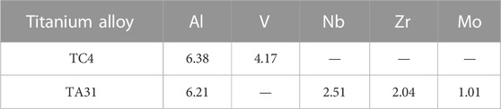
TABLE 1. Main chemical composition of titanium alloy (mass fraction, %).

FIGURE 1. Microstructure of the tested TA31 titanium alloy.
The aim of this experiment is to study the plastic hardening behavior and failure mechanism of TA31 alloy. Four types of specimens are designed to represent different stress states, as shown in Figure 2, including smooth round bar (SRB) tensile test, notched round bar tensile test with different notch radius R (NRB) and shear-induced specimens test (Shear).
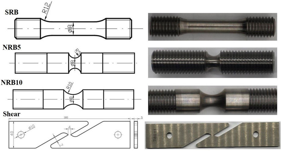
FIGURE 2. Specimen geometries.
In the test, an electronic extensometer with a gauge distance of 50 mm is used to obtain the load-displacement curve until the fracture, and the test load is controlled by displacement. In order to capture the fracture position within the gauge length, a slow loading rate (2 mm/min) is adopted.
The measured yield strength and ultimate strength of TA31 alloy are 813MPa and 881 MPa respectively, and Young’s Modulus is 118 GPa There is no obvious yield platform for TA31 alloy, and notch size has great influence on bearing capacity and elongation of samples. Figure 3 shows the different macro-fracture phenomena, such as SRB, NRB with different notch radius and shear-induced specimens. The size of oblique shear lip decreases with the decrease of notch radius, which indicates that the influence of the shear fracture mechanism is gradually weakened. On the contrary, very small and almost zero dimples appear on the smooth fracture surface of the shear-induced specimens, and the necking phenomenon is not observed.
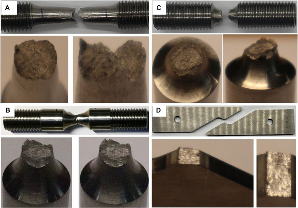
FIGURE 3. The fracture surfaces: (A) smooth round bar, (B) notched round bar, R = 10 mm, (C) notched round bar, R = 5 mm, (D) shear-induced specimen.
The plasticity model and damage model will be formulated in terms of invariants of stress tensor, such as the equivalent stress
Where σ1, σ2 and σ3 denote principal stresses. The plane stress state is dominant in the most of pressure-hulls for deep-sea equipment. It was shown by Xue (Xue and Wierzbicki, 2008) and Wierzbicki that the condition σ3 = 0 relates the parameters η and L as shown in Eq. 5.
Eq 5 calculates the corresponding value for the stress triaxiality under plane stress with a given Lode parameter between [-1, 1]. In this paper, the fracture loci under plane stress will be depicted in the space of (η,
The Johnson-Cook plasticity model (Johnson and Cook, 1985) is an empirical model for metals subjected to large strains, high strain rates and high temperatures.
Where
Based on the J-C model, Zhang (Zhang et al., 2022c) developed a new plasticity model of TA31 titanium, which was short for Modified Johnson-Cook (MJC) model. In order to consider the pressure sensitivity effect, a parameter accounting for stress triaxiality was introduced into the strain hardening modulus, B, and hardening exponent, n, as described in Eq. 8.
Where b1∼b3, n1∼n3 are parameters to be determined. Table 2 shows the obtained parameters for MJC model of TA31 titanium alloy after the calibration.
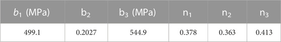
TABLE 2. Hardening model parameters for MJC model of TA31 titanium alloy.
Damage is considered as a thermodynamic state variable, which characterizes the deterioration of the material. Assuming that the distribution of damage is isotropic, the value of damage in all directions can be shown by the scalar factor D. The progressive damage of a ductile material is based on the change of the shape and the number of voids within the material, which can also be represented by the change of the Young’s modulus of material, as shown in Eq. 9. According to the strain equivalence hypothesis (Lemaitre, 1985), the constitutive equations of a damaged material are the same of the virgin material with no damage where the stress is simply replaced by the effective stress, and the value of the strain in the damaged material is equal to the value of the strain in the undamaged material with a stress value, as shown in Eq. 10.
Where σeff is the effective stress, σ is the stress value in the damaged material, and E0 and Eeff are the Young’s modulus of the undamaged and damaged material, respectively. In the absence of any coupling between the damage and plasticity dissipation potentials, the total dissipation potential is given by linear superposition of the dissipation potential with plastic deformation, fp, and the damage dissipation potential, FD, for the Bonora damage model (Bonora, 1997). The damage dissipation is assumed to depend on the deformation history, where the damage, D, variable is coupled with plastic strain, as formulated in Eq. 12.
Where S0 is a material constant, α is damage exponent that determines the shape of the damage evolution curve, n is the hardening exponent of plasticity model in a power-law form, Dcr is the value of damage at failure, and p is equivalent plastic strain. The damage associated variable Y, which is called damage strain energy release rate, is defined as Eq. 13.
Where μ is Poisson’s ratio, and η is stress triaxiality. By normality rule, the following expression for the kinetic law of damage evolution can be obtained in Eq. 14.
Under the assumption of proportional loading condition, the damage evolution is given according to the following expression.
Where pth is the threshold strain under multiaxial stress at which damage process are initiated, and
In this paper, The FEA models are established in the ABAQUS/explicit platform to simulate the foregoing quasi-static tests. Damage behavior and failure stain could be predicted by FEA simulation using an appropriate developed subroutine VUMAT. Instead of separating the elements, an element is removed if the critical damage value of the material point is reached. Figure 4 shows the FEA models used in this paper. Three dimensional hexahedral elements with reduced integration (C3D8R) are employed, and the minimum element size is kept to be 0.1 mm in the minimum section. Adaptive meshing is employed to avoid element distortion in the large plastic deformation. Taking the advantage of symmetry to reduce computing time, one-eighth of the model is adopted for round bar specimens, and a half of the model is used for shear specimens making a half of the thickness.
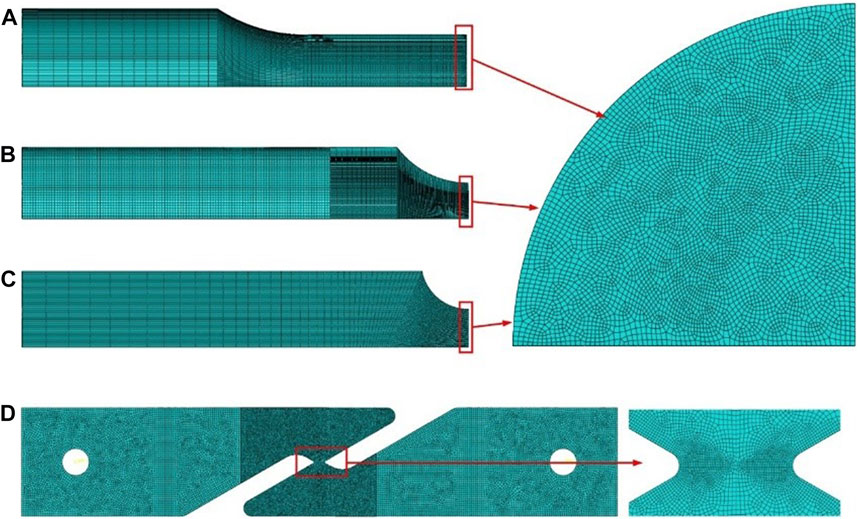
FIGURE 4. Typical FEA models of the selected tension tests: (A) smooth round bar, (B) notched round bar, R = 10 mm, (C) notched round bar, R = 5 mm, (D) shear-induced specimen.
Damage threshold strain indicates the strain level at which damage process starts to take place, and voids nucleation are large enough to affect the material stiffness at this stage. In order to simplify, the damage threshold strain is equal to the uniaxial plastic threshold strain
The mechanical responses and failure mechanisms of specimens in different stress states are quite different as shown in Figure 5, which shows the load-displacement curves predicted by FEA simulation and those obtained in the tests. A similar tendency is observed between the experimental and numerical results for the tensile tests with the round bar specimens, and the critical points are located in the center region of the minimum section, and the maximum load occurs at the beginning of necking. Whereas the maximum load of shear-induced specimens occurs until complete fracture, and the critical point is located at the outer surface, as shown in Figure 5D.
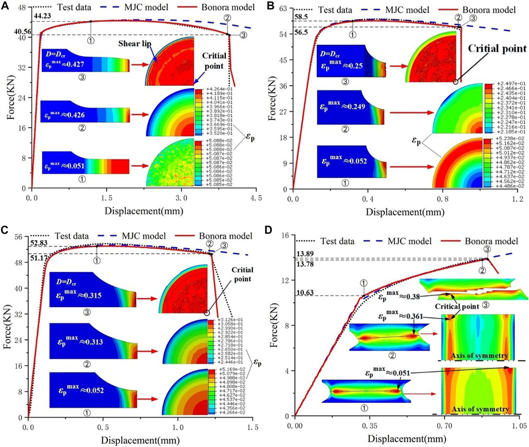
FIGURE 5. Load versus displacement curves obtained in the tests and FEA simulation: (A) the smooth round bar (
Owing to the absence of the softening behavior of material, the MJC model can only accurately predict the load-displacement relationship before necking from this figure. It can be seen that the numerical results based on the Bonora model are in good agreement with the results of tests. However, the damage parameters (
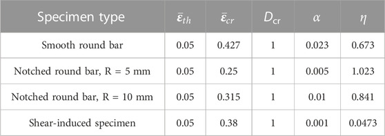
TABLE 3. The parameters for Bonora damage model.
Failure strain is the strain at the end of plastic deformation, or right before final crack at the point where fracture initiates. Measure of failure strain is a big challenge in the tests. Because fracture initiates inside of metals, it is impossible to measure the moment of fracture. The failure strain obtained from the foregoing tests is the mean value of the specimen, which is lower than the strain in the interior of necking section as shown in Figure 6.

FIGURE 6. Stress versus plastic strain for smooth round bar.
Currently, a hybrid experimental-numerical approach has been widely employed to obtain failure strain. In this method, tests are committed at first and load-displacement curves are recorded. Then these tests are simulated based on FEA model and the failure strains are extracted from simulations at the fracture onset. In this paper, this hybrid experimental-numerical method is adopted to measure failure strains in smooth round bar specimens, notched round bar specimens and shear-induced specimens for TA31 alloy. As shown in Figure 5 above, it is observed that the predicted fracture onset based on the Bonora damage model agrees well with tests for all of the specimens. Simultaneously, the evolution of stress triaxiality with plastic strain of fracture onset can be obtained from numerical analysis of the forgoing tests as shown in Figure 7. It can be found that as the stress triaxiality increases, the failure strain
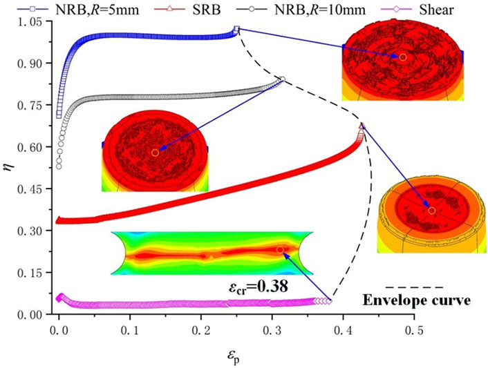
FIGURE 7. Equivalent plastic strain versus stress triaxiality for the critical point of each specimens.
The stress state plays a significant role in determining the parameter of Bonora damage model. As shown in Figure 8, both
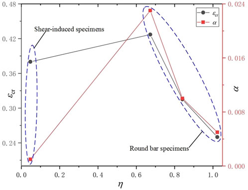
FIGURE 8. Stress triaxiality versus damage parameters.
The changes in stress triaxiality and equivalent plastic strain are non-proportional with increasing load, and the distributions are predicted by FEA simulation with Bonora damage model in Figure 9 and Figure 10. Figure 9A shows that the εp-value and the η-value remain 0.0508 and 0.333 respectively across the minimum section before damage initiates for the smooth round bar specimens, whereas the value of the notched round bar specimens exhibit a larger variation across the minimum section. Figure 9B shows that the εp-value and the η-value decrease from the center point to the outer surface along the minimum section, which indicates that the crack is predicted to start from the center of the section and to propagate towards the outer surface for the round bar specimens.

FIGURE 9. Distributions of stress triaxiality and equivalent plastic strain for round bar specimens: (A) the initiation of damage, (B) the initiation of crack.
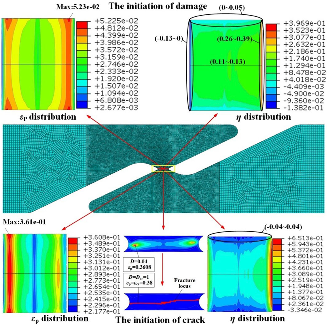
FIGURE10. Distributions of stress triaxiality and equivalent plastic strain for shear specimens.
For the shear-induced specimens, the η-value varied greatly around zero, which indicates that pure shear deformation does not exist in practice. However, As shown in Figure 10, the η-value remain minor across the outer surface, which is approximate to the pure shear state. The critical point is located at the shear slip band which is at the outer surface close to the edge of the shear gauge.
Scanning electron microscope (SEM) images of the fracture surface have been acquired to analyze the fracture mechanism. In the round bar specimens, many dimples of varying size are present on the fracture surface as shown in Figures 11(A–C). It can be found that the size of the dimple varies with the notch radius. The SRB specimens with the smallest triaxiality produces the largest dimple, whereas the NR5 specimen with the highest triaxiality produces the smallest dimple. However, in the shear-induced specimens, as shown in Figure 11D, very minor microvoids appear on the smooth fracture surface. Qi (Qi et al., 2017) pointed out that the growth of cavity is the comprehensive effect of shear stress and tension stress. Hence, higher stress triaxiality, where tension stress plays a dominant role, will promote the isotropic enlargement of microvoids, which will lead to the constriction of the ligament between two voids before shear aggregation. In addition, it seems that the high hydrostatic stress, on behalf of high stress triaxiality, will enhance the expansion of spherical cavity. In the shear-induced specimens, the stress triaxiality is close to zero, and the shear stress dominates, resulting in the elongation of the voids in the fracture along the shear fracture direction. The above research shows that the deformation mechanism of micro voids of TA31 alloy is greatly influenced by the stress state, which is also the result of competition between shear mechanism and tension mechanism in the plastic deformation process.
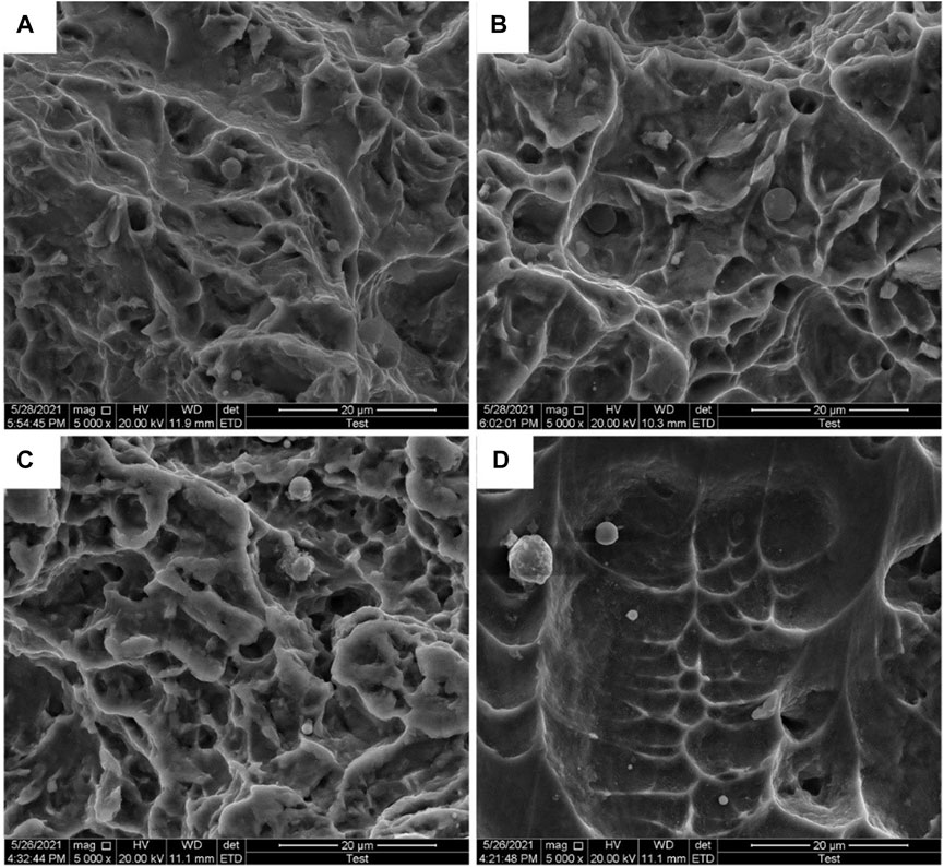
FIGURE 11. The SEM fractographies (5,000×): (A) smooth round bar, (B) notched round bar, R = 10 mm, (C) notched round bar, R = 5 mm, (D) shear-induced specimen.
The evolution of the internal microvoids is varying with stress triaxiality, which is also illustrated briefly in Figure 12. The SRB specimens are under uniaxial load with
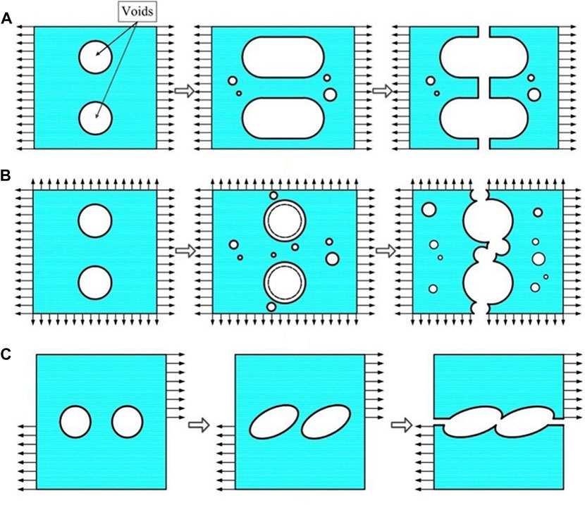
FIGURE 12. The evolution of the voids under diverse stress states: (A) the evolution of voids for SRB specimens; (B) the evolution of voids for NRB specimens; (C): the evolution of voids for Shear-induced specimens.
In this paper, the investigation of fracture mechanism and failure strain with different stress triaxiality for TA31 titanium alloy have been committed. This study has furthered our understanding of the applicability of MJC model and Bonora damage model in the process of plastic deformation and ductile fracture. A series of tests, including round bar specimens with different notched radius and shear-induced specimen, have been carried out to generate diverse facture mechanism under different stress state, covering a wide range of η. By employing the FEA simulation, parameter study has been performed to get a better understanding of Bonora damage model.
(1) Owing to the absence of the softening behavior of material, the MJC model can only accurately predict the load-displacement relationship before necking. After the threshold value of plastic strain (
(2) The Bonora damage model can be used to predict failure strain and fracture location of TA31 titanium alloy. Based on the Bonora damage model, a hybrid experimental-numerical approach is performed to obtain the failure strain for all of the specimens accurately. Nevertheless, the damage parameters are sensitive to the stress triaxiality. α and
(3) The fracture mechanism of TA31 titanium is the result of competition between shear mechanism and tension mechanism, and the fracture mechanism is critical to plastic deformation process. It is important to remark that Bonora model with constant parameters is not enough to predict the failure strain and damage evolution. From a practical point of view, it is better to choose a series of calibration tests close to the real application loading condition to guarantee appropriate accuracy of the results, and the Bonora damage model need to be modified to take stress triaxiality into consideration for determining the parameter in the further. At the same time, this paper does not consider the anisotropy of titanium alloys, which will also be studied in the future.
The raw data supporting the conclusion of this article will be made available by the authors, without undue reservation.
ZW is considered to be someone who has made substantive intellectual contributions to this study. ZW has instructed the tests of TA31 titanium alloy. ZW has also revised this paper critically for important intellectual content. All authors listed have made a substantial, direct, and intellectual contribution to the work and approved it for publication.
The authors declare that the research was conducted in the absence of any commercial or financial relationships that could be construed as a potential conflict of interest.
All claims expressed in this article are solely those of the authors and do not necessarily represent those of their affiliated organizations, or those of the publisher, the editors and the reviewers. Any product that may be evaluated in this article, or claim that may be made by its manufacturer, is not guaranteed or endorsed by the publisher.
Allahverdizadeh, N., Andrea, G., Manes, A., and Giglio, M. (2015). An experimental and numerical study for the damage characterization of a Ti–6Al–4V titanium alloy. Int. J. Mech. Sci. 93, 32–47. doi:10.1016/j.ijmecsci.2015.01.005
Bao, Y., and Wierzbicki, T. (2004). On fracture locus in the equivalent strain and stress triaxiality space. Int. J. Mech. Sci. 46 (1), 81–98. doi:10.1016/j.ijmecsci.2004.02.006
Bonora, N. (1997). A nonlinear CDM model for ductile failure. Eng. Fract. Mech. 58 (1), 11–28. doi:10.1016/s0013-7944(97)00074-x
Bonora, N., Gentile, D., Pirondi, A., and Newaz, G. (2005). Ductile damage evolution under triaxial state of stress: Theory and experiments. Int. J. Plasticity 21 (5), 981–1007. doi:10.1016/j.ijplas.2004.06.003
Bonora, N., Ruggiero, A., Esposito, L., and Gentile, D. (2006). CDM modeling of ductile failure in ferritic steels: Assessment of the geometry transferability of model parameters. Int. J. Plasticity 22, 2015–2047. doi:10.1016/j.ijplas.2006.03.013
Bonora, N., Testa, G., Ruggiero, A., Iannitti, G., and Gentile, D. (2020). Continuum damage mechanics modelling incorporating stress triaxiality effect on ductile damage initiation. Fatigue and Fract. Eng. Mater. Struct. 43 (8), 1755–1768. doi:10.1111/ffe.13220
Cao, T. S., Gachet, J. M., Montmitonnet, P., and Bouchard, P. O. (2014). A Lode-dependent enhanced Lemaitre model for ductile fracture prediction at low stress triaxiality. Eng. Fract. Mech. 124, 80–96. doi:10.1016/j.engfracmech.2014.03.021
Choung, J., Nam, W., Lee, D., and Song, C. Y. (2014). Failure strain formulation via average stress triaxiality of an EH36 high strength steel. Ocean. Eng. 91, 218–226. doi:10.1016/j.oceaneng.2014.09.019
Choung, J., Shim, C-S., and Song, H. C. (2012). Estimation of failure strain of EH36 high strength marine structural steel using average stress triaxiality. Mar. Struct. 29, 1–21. doi:10.1016/j.marstruc.2012.08.001
Johnson, G. R., and Cook, W. H. (1985). Fracture characteristics of three metals subjected to various strains, strain rates, temperatures and pressures. Eng. Fract. Mech. 21, 31–48. doi:10.1016/0013-7944(85)90052-9
Jorge, L. M., Julio, C. R., and Murilo, A. V. (2017). Continuum damage mechanics applied to numerical analysis of ship collisions. Mar. Struct. 56, 206–236. doi:10.1016/j.marstruc.2017.08.003
Kim, J., and Reddy, J. N. (2016). Modeling of functionally graded smart plates with gradient elasticity effects. Mech. Adv. Mater. Struct. 27, 437–447. doi:10.1080/0145935x.2016.1199188
Lemaitre, J. (1985). A continuous damage mechanics model for ductile fracture. J. Eng. Mater. Technol. 107, 83–89. doi:10.1115/1.3225775
Lou, Y., Chen, L., Clausmeyer, T., Tekkaya, A. E., and Yoon, J. W. (2017). Modeling of ductile fracture from shear to balanced biaxial tension for sheet metals. Int. J. Solids Struct. 112, 169–184. doi:10.1016/j.ijsolstr.2016.11.034
Lou, Y., Huh, H., Lim, S., and Pack, K. (2012). New ductile fracture criterion for prediction of fracture forming limit diagrams of sheet metals. Int. J. Solids Struct. 49 (25), 3605–3615. doi:10.1016/j.ijsolstr.2012.02.016
Lou, Y., and Yoon, J. W. (2015). Anisotropic behavior in plasticity and ductile fracture of an aluminum alloy. Key Eng. Mater. 651, 163–168. doi:10.4028/www.scientific.net/kem.651-653.163
Luo, J., Li, S. Q., and Li, H. (2008). High temperature deformation behavior of TC4 titanium alloy and its flows stress model. Chin. J. Nonferrous Metals 18 (8), 1395–1401.
Park, S. J., Lee, K., Choung, J., and Walters, C. L. (2019). Ductile fracture prediction of EH36 grade steel based on Hosford–Coulomb model. Ships Offshore Struct. 14, 219–230. doi:10.1080/17445302.2019.1565300
Park, S. J., Lee, K., Choung, J., and Walters, C. L. (2018). Ductile fracture prediction of high tensile steel EH36 using new damage functions. Ships Offshore Struct. 13, 68–78. doi:10.1080/17445302.2018.1426433
Qi, H., Li, X., Han, X., and Chen, J. (2017). A new shear and tension based ductile fracture criterion: Modeling and validation. Eur. J. Mech. A-Solids 66, 370–386. doi:10.1016/j.euromechsol.2017.08.005
Shamshiri, A. R., Haji Aboutalebi, F., and Poursina, M. (2021). A new numerical approach for determination of the Lemaitre’s ductile damage parameter in bulk metal forming processes. Archive Appl. Mech. 91 (10), 4163–4177. doi:10.1007/s00419-021-01998-y
Testa, G., Bonora, N., Ruggiero, A., Iannitti, G., and Gentile, D. (2020). Stress triaxiality effect on void nucleation in ductile metals. Fatigue and Fract. Eng. Mater. Struct. 43 (7), 1473–1486. doi:10.1111/ffe.13212
Thamburaja, P., Sarah, K., Srinivasa, A., and Reddy, J. N. (2019). Fracture of viscoelastic materials: FEM implementation of a non-local and rate form-based finite-deformation constitutive theory. Comput. Methods Appl. Mech. Eng. 354, 871–903. doi:10.1016/j.cma.2019.05.032
Xue, L., and Wierzbicki, T. (2008). Ductile fracture initiation and propagation modeling using damage plasticity theory. Eng. Fract. Mech. 75, 3276–3293. doi:10.1016/j.engfracmech.2007.08.012
Zhang, B. W., Wan, Z. Q., and Zhang, A. F. (2022). Effect of stress triaxiality on the failure behaviora of TA31 titanium alloy. J. Ship Mech. 26 (10), 1485–1495.
Zhang, J., Dai, M. Q., Wang, F., Tang, W. X., Zhao, X. L., and Zhu, Y. M. (2022). Theoretical and experimental study of the free hydroforming of egg-shaped shell. Ships Offshore Struct. 17 (2), 257–267. doi:10.1080/17445302.2020.1827637
Zhang, J., Di, C. Y., Wang, F., and Tang, W. X. (2021). Buckling of segmented toroids under external pressure. Ocean. Eng. 239, 109921–110012. doi:10.1016/j.oceaneng.2021.109921
Zhang, J., Liu, C., Tang, W. X., Wang, F., Zhao, X. L., Zhang, J. F., et al. (2022). Collapse of barreled frustums under external hydrostatic pressure. Mar. Struct. 84, 103218. doi:10.1016/j.marstruc.2022.103218
Keywords: TA31 titanium alloy, stress triaxiality, fracture mechanism, bonora damage model, finite element analysis
Citation: Zhang B and Wan Z (2023) Fracture mechanism and failure strain of TA31 titanium alloy for deep-sea pressure hulls based on continuum damage mechanics. Front. Mater. 10:1117520. doi: 10.3389/fmats.2023.1117520
Received: 06 December 2022; Accepted: 19 January 2023;
Published: 03 February 2023.
Edited by:
Yongmei Zhu, Jiangsu University of Science and Technology, ChinaReviewed by:
Napat Vajragupta, VTT Technical Research Centre of Finland Ltd., FinlandCopyright © 2023 Zhang and Wan. This is an open-access article distributed under the terms of the Creative Commons Attribution License (CC BY). The use, distribution or reproduction in other forums is permitted, provided the original author(s) and the copyright owner(s) are credited and that the original publication in this journal is cited, in accordance with accepted academic practice. No use, distribution or reproduction is permitted which does not comply with these terms.
*Correspondence: Bowen Zhang, Ym93ZW4xMjI0MTkwNjlAMTI2LmNvbQ==
Disclaimer: All claims expressed in this article are solely those of the authors and do not necessarily represent those of their affiliated organizations, or those of the publisher, the editors and the reviewers. Any product that may be evaluated in this article or claim that may be made by its manufacturer is not guaranteed or endorsed by the publisher.
Research integrity at Frontiers
Learn more about the work of our research integrity team to safeguard the quality of each article we publish.