 Yifan Dong1
 Denghui Liu
 Xiurong Zuo
- 1Key Laboratory of Material Physics, Ministry of Education, School of Physics and Microelectronics, Zhengzhou University, Zhengzhou, China
- 2School of Electrical and Information Engineering, Zhengzhou University, Zhengzhou, China
The relationship between the microstructure and the mechanical and corrosion properties of a welded joint of 620-grade marine steel was studied using metallographic microscopy, scanning electron microscopy, an energy dispersive spectrometer, transmission electron microscopy, and microhardness and tensile tests. The results showed that the strength and hardness of the weld center area (WMmid) were higher than those of the inner and outer welding surface region (WMin and WMout) because the volume fraction of the martensite-austenite (MA) constituents (21.6%) was higher than that in WMin and WMout (18.0% and 14.3%, respectively). There were numerous MnO-Al2O3-SiO2-TiO2-type inclusions located at the bottom of dimples in the fracture surface; however, the MA constituents took precedence over this kind of inclusion in inducing pitting corrosion. In contrast, pitting corrosion can be initiated by Al2O3-MgO-CaO-CaS inclusions in the heat-affected zone (HAZ) and base metal (BM). The corrosion resistance of the welded joint was in the order of weld metal > HAZ > BM. The WMmid with smaller dendrite spacing and a larger size of MA constituents had better corrosion resistance compared with the WMin and WMout. The corrosion resistance of the HAZ decreased in the sequence of coarse grain HAZ, fine grain HAZ, and intercritical HAZ.
1 Introduction
620-grade marine steels used in the construction of various ships have high strength and toughness to resist the external load. However, during the welding process of marine steels, the existence of the thermal effect is inevitable, which causes changes in the microstructure of the welded joint (Li et al., 2011; Yang et al., 2015; Poberezhnyi et al., 2016; Chu et al., 2020; Kumar et al., 2021), which then inevitably affects the mechanical properties of the materials. Furthermore, marine steels are susceptible to pitting corrosion with the presence of aggressive anions and dissolved oxygen in the service environment (Ma et al., 2015; Cui et al., 2016).
During the welding process, the weld metal (WM) forms a multiphase structure. The fine martensite–austenite (MA) constituents and intragranular acicular ferrite (IAF) in the WM show excellent strength, low temperature toughness, and excellent corrosion resistance (Wang et al., 2015; Dong et al., 2022; Liu et al., 2022). The heat-affected zone (HAZ) is formed by the temperature field effect between the molten WM and the adjacent matrix. The coarse bainite structure formed in the coarse grain HAZ (CGHAZ) is deteriorative to the toughness and corrosion resistance of the material (Ma et al., 2018; Dong et al., 2022). A double-phase structure is formed in the intercritical HAZ (ICHAZ), affecting the strength and toughness of the material and significantly reducing the corrosion resistance of the material (Ma et al., 2018; Rodrigues et al., 2021).
Shibaeva et al. (2014) suggested that microstructure features with a different content of alloy elements (e.g., carbon, manganese) may cause the formation of galvanic pairs, with the current densities of various microstructures increasing in a sequence of ferrite–bainite, ferrite–pearlite, and ferrite–martensite, thus indicating the deterioration of corrosion resistance in this order. Additionally, oxide and sulfide inclusions have been recognized as the key factors to induce pitting corrosion in many studies (Krawiec et al., 2006; Li et al., 2016; Liu et al., 2017; Dong et al., 2020; Kovalov et al., 2022). With high grain boundary energy at the interface of the Al-Mg-Ca-O-S inclusion and matrix, pitting usually occurs at the inclusion, inducing the initiation of circle pitting corrosion, due to the adsorption and electromigration of chloride ions (Zheng et al., 2013; Fan et al., 2017; Wang et al., 2018a). In contrast, inclusions containing SiO2 with high chemical stability exhibit better corrosion resistance (Li et al., 2016). Furthermore, the pitting is greatly inclined to be initiated at the MA and carbides located at the grain boundaries, deteriorating the corrosion resistance of steels (Wang et al., 2018b).
The microstructure of the welded joint varies greatly with multiple welding passes, and Al-Mg-Ca-O-S inclusions are the main types of inclusion in aluminum killed steel, which is different from the WM-containing SiO2 inclusions. Therefore, it is necessary to study the influence of the microstructure characteristics and inclusion types of the welded joint on the strength and corrosion resistance of the materials, especially high-strength marine steels. In the present study, the mechanical properties of the welded joint of 620-grade marine steel were tested by tensile tests, and the relationship between the microstructure and the mechanical properties of the welded joint was analyzed. Furthermore, the mechanism of pitting corrosion was also studied in the weld joint.
2 Experimental procedures
The as-received state of the steel plate with a thickness of 10 mm was quenched at 880°C, followed by water cooling, and tempered at 650°C, followed by air cooling. The chemical components (wt.%) of the marine steel were C 0.07, Si 0.25, Mn 0.80, Cr 1.30, Ni 1.80, Mo 0.20, P 0.007, S 0.0005, and Fe in balance.
The welding process for the longitudinal submerged-arc welding was conducted using two internal-welding passes (WM1 and WM2) and three outer-welding passes (WM3, WM4, and WM5) with a Y-type groove. The macroscopic morphology of the welded joint is shown in Figure 1. The welded joint includes the WM, HAZ, and base metal (BM, near the HAZ). The HAZ can be divided into the CGHAZ, the fine grain HAZ (FGHAZ), and the ICHAZ (Li et al., 2011; Dong et al., 2022).
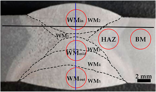
FIGURE 1. Macroscopic morphology of the welded joint.
Prior to hardness testing, the welded joint sample was ground, mechanically polished, and etched in a 4% nital solution. The microhardness distributions on the cross section of the welded joint were measured using a HXD-2000TMSC/LCD Vickers hardness tester with a force of 1,000 gf and a dwell time of 15 s. The two hardness marking lines were along the transverse and thickness directions, respectively. The former was located at 2 mm from the surface of the inner welding zone (marked by the black solid line in Figure 1), and the latter was located at the thickness direction of the WM center (marked by the blue line in Figure 1). Tensile tests were performed on a SANS CMT 5105 electronic universal tester at room temperature. In line with GB/T 228.1-2010, round tensile specimens with a gauge diameter of 3.5 mm and a gauge length of 17.5 mm were adopted on the locations of the inner welding surface region (WMin: the second pass, WM2), the weld center area (WMmid: the third and the fourth passes, WM3 and WM4), and the outer welding surface region (WMout: the fifth pass, WM5), marked by red circles in Figure 1.
For the original microstructure observation, specimens for JSM 6700F scanning electron microscope (SEM) observation were etched with 4% nitric acid alcohol solution. After nine images were selected using the nine square format, the proportion fraction of the hard phase structure (MA constituent + carbide) contained in each tensile sample was calculated using Image-Pro Plus (IPP) software. After polishing, the welded joint was immersed in saturated picric acid solution for 10 s to observe the dendrite morphology using an OLYMPUS BX51M metallographic microscope (OM). The average of the dendrite spacing in the WM was measured using IPP software. The thin foils for the WM, which were prepared using a double jet electro-polisher in a mixed solution of 10 mL perchloric acid and 90 mL of ethanol at –20°C under a voltage of 20 V, were examined using JEM-2100F transmission electron microscopy (TEM).
To characterize the pitting corrosion resistance, the welded joint was immersed in 3.5 wt.% NaCl solution at room temperature for 40 s after polishing. The corrosion morphology of the welded joint was observed under OM and SEM. The core of the pitting corrosion was assessed using an INCA-ENERGY energy dispersive spectrometer (EDS).
3 Results
3.1 Mechanical properties of the welded joint
Figure 2A shows the hardness variation at the center of the WM along the thickness direction. It can be seen that the hardness values of WM1 and WM3 in the center welding passes were higher than those of WM2, WM4, and WM5, with the low trough of hardness at the junction of the adjacent weld passes. Figure 2B shows the hardness variation of the welded joint at a distance of 2 mm from the inner surface along the transverse direction. It can be seen from Figure 2B that the hardness value of the HAZ was significantly higher than those of the WM and BM. Furthermore, it is worth noting that the hardness value of the junction zone between the HAZ and BM decreased first and then increased. In addition, the hardness value of the fusion line (FL) was lower than that of the surrounding area. A similar hardness distribution was obtained in Królicka et al.’s (2020) study on the welded joints of bainite steel.
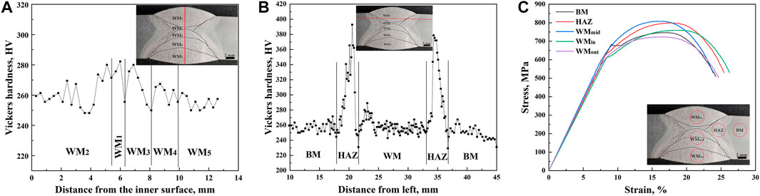
FIGURE 2. Curves of the hardness variation along the thickness (A) and transverse (B) direction and the stress–strain (C) of the welded joint.
The stress–strain curves shown in Figure 2C and the corresponding tensile properties in Table 1 show that there was a yield platform in the tensile curve of the BM, with a yield strength of 685 MPa, and the yield ratio was as high as 91.82%. There was an inflection point in the tensile curves of the HAZ and WMin, the yield strengths of which were higher than 600 MPa, and the yield ratio was approximately 80%. The tensile curves of the WMmid and WMout showed continuous yield, and the yield ratios of less than 76% were the lowest observed. The strength of the WMmid containing WM3 and WM4 with high hardness was higher than those of the WMout and WMin with low hardness. Similarly, the strength of the HAZ with high hardness was higher than those of the BM, WMout, and WMin with low hardness. The area reduction of the WM was smaller than that of the BM and the HAZ, implying a poor plastic deformation ability (Table 1).
TABLE 1. Tensile properties of the welded joint.
3.2 Fractography
The SEM fracture morphology of the tensile specimens of the welded joint is shown in Figure 3. The top view of the fracture surface of the WMin and WMmid specimens was approximately circular, which was divided into the elliptic-shaped fiber zone at the center and the shear-lip zone at the outer periphery, whereas circular-shaped fiber zones were found for the HAZ and BM. The fracture surface sizes of the HAZ and BM samples were essentially the same, which were smaller than those of the WMin and WMmid samples, indicating more significant necking in the HAZ and BM.

FIGURE 3. Top view and detailed view of the tensile tested fracture surface. For the WMin, (A) the fiber zone and (B) the shear-lip zone; for the WMmid, (C) the fiber zone and (D) the shear-lip zone; for the HAZ, (E) the fiber zone and (F) the shear-lip zone; and for the BM, (G) the fiber zone and (H) the shear-lip zone.
In the center of the fiber zone of the WMin and WMmid specimens, there was a large amount of equiaxed fine dimples with a certain number of cleavage facets. The detailed view of the shear-lip zone, marked by a white box, was characterized by shear dimples and tear ridges as a result of shear stress. For the WMin, the number of cleavage facets was more than for the WMmid (Figures 3A, C), indicating that the WMmid had better ductility than the WMin. In addition, it is worth noting that the presence of different-sized spherical inclusions was located at the bottom of dimples in the WMin and WMmid specimens. The difference in deformation properties between the inclusions and the nearby matrix led to the formation of dimples as a result of stress concentration at the interface between them (Wu et al., 2013; Pandey et al., 2017; Pandey et al., 2019).
In the center of the fiber zone of the HAZ, fine dimples, deep dimples, a small amount of fine cleavage facets, and secondary cracks were observed to reveal the ductile dimple fracture (Figure 3E). The shear-lip zone displaying a quasi cleavage fracture with a certain amount of large-size shear dimples is shown in Figure 3F. For the BM, the fracture characteristic was similar to that of the HAZ, but the number of cleavage facets was observed to be slightly increased in the fiber region, as shown in Figure 3G. In addition, there were no obvious inclusions existing at the bottom of the dimples in both the HAZ and BM. Because of the low content of S and O in the investigated steel, there were few inclusions in both the HAZ and BM, which can induce ductile dimples. It can be concluded that precipitates or MA were the key factors that caused ductile dimple fractures and cleavage fractures, which were associated with the decohesion of the precipitated particle–matrix interface (Chatterjee et al., 2014; Liu et al., 2015).
The fiber zones of the HAZ and BM were almost circular-shaped, and the degree of necking was obviously more serious than that of the WM with an elliptic-shaped fiber zone. In addition, there were a large number of deep dimples in the fiber zone of the HAZ and BM, indicating that the plastic deformation ability of the HAZ and BM was more excellent than that of the WM with slightly-large shallow dimples.
3.3 Microstructure of the welded joint
3.3.1 Microstructural features of the weld
Figure 4 shows the microstructure of the welded joint by OM and SEM. The microstructure of the WM exhibited the characteristic of dendrite morphology, and the direction of the dendrite was perpendicular to the FL (Wu et al., 2020). By observing Figures 4C, F, I, L, O, it can be seen that the dendrite spacing in WM2 and WM5 was significantly larger than those in WM1, WM3, and WM4, although the dendrite morphology of WM5 was not as obvious as that of WM2.
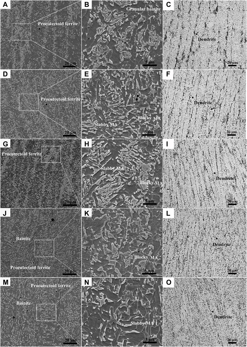
FIGURE 4. SEM and OM morphologies of WM2 (A–C), WM1 (D–F), WM3 (G–I), WM4 (J–L), and WM5 (M–O).
As shown in Figure 4, granular bainite with various-sized MA constituents aggregated into bands and proeutectoid ferrite was distributed between the bands, with a small size of fine MA constituents at the grain boundaries. Due to the overlap of the welding layers, WM1, WM3, and even WM4 were subjected to the thermal effect of subsequent welding passes, resulting in the uniform diffusion of alloying elements and the dense distribution of MA constituents with a slabby and blocky shape, as shown in Figures 4D, G, J (Dong et al., 2022). Additionally, a large proportion of supergiant slabby and blocky MA constituents were distributed on WM3. Due to the slow cooling resulting from the heat insulation of the flux in WM2 and WM5 located in the surface area, the microstructure included a large volume fraction (f) of proeutectoid ferrite (Figures 4A, M), resulting in low hardness in WM2 and WM5 (Figure 2A).
3.3.2 Microstructural features of the HAZ and BM
The high temperature of the molten WM leads to the inevitable formation of the HAZ in the welding process. Except for the zones near WM2 and WM5, the HAZ particularly near the FL location had been heated many times during the welding process. The SEM and OM morphology of the BM and HAZ is shown in Figure 5. The microstructural characteristic of the CGHAZ, which was formed with a peak temperature of about 1,350°C (Poberezhnyi et al., 2016; Dong et al., 2022), was identified as bainite with a large number of MA constituents uniformly distributed in the ferrite matrix (Figure 5B). Due to the tempering effect of other weld passes, there was mostly a large size of MA constituents with a round edge in the CGHAZ. For the FGHAZ, the peak temperature was slightly higher than the Ac3 leading to small-size granular bainite with a dense distribution of MA constituents, due to the rapid cooling (Figure 5C). The relatively higher hardness of the FGHAZ can be attributed to the fine-grained strengthening and second-phase strengthening effect of the MA constituents or carbides (Ma et al., 2020). The peak temperature of the ICHAZ was between Ac1 and Ac3. The ICHAZ microstructure with ferrite plus granular bainite, which were distributed alternately, showed obvious bands parallel to the surface of the steel plate (Figure 5D). Fine MA constituents were mainly concentrated in the bainite band zone and some were scattered in the ferritic grain boundary. The microstructure of the BM was high-temperature tempered martensite, with large-sized granular carbides dispersed at the grain boundaries and lath boundaries (Figure 5E).
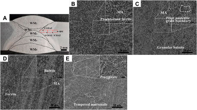
FIGURE 5. Macro location of each area of the HAZ (A) and SEM morphologies of the CGHAZ (B), FGHAZ (C), ICHAZ (D), and BM (E).
3.4 Pitting corrosion of the welded joint
Figure 6 shows the metallographic morphology of the welded joint immersed in 3.5% sodium chloride solution. It can be concluded that the corrosion resistance of the WM was obviously higher than that of the HAZ and BM. However, the WM exhibited inhomogeneous corrosion. There was a small number of corrosion pits in WM1, WM3, and WM4, while a large number of large pits existed in WM2 and WM5. Furthermore, the pitting corrosion in WM2 was mostly distributed in the near surface area. The corrosion resistance from high to low was WM1/WM3, WM4, WM5, and WM2. In addition, there were also differences in the corrosion resistance of the HAZ as, far from the WM, the corrosion resistance of the HAZs gradually decreased.
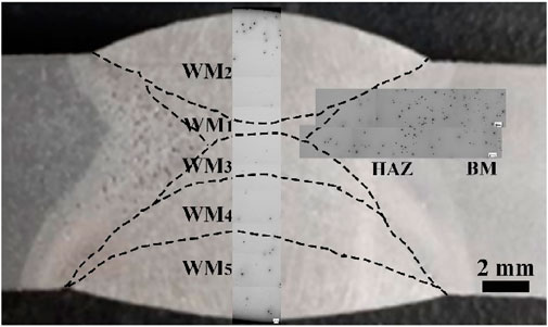
FIGURE 6. Metallographic morphology of the weld joint after immersion.
Figure 7 shows the morphology of the stable pitting corrosion in the HAZs. Although the microstructure characteristics were different in different regions of the HAZ, the corrosion pits all contained obvious cores. There were obvious bands in the corrosion pits of the ICHAZ and BM, which were consistent with the direction of the microstructural bands. It has been demonstrated that the micro galvanic effect between hard and soft phases leads to electrochemical corrosion (Kadowaki et al., 2019; Rajput et al., 2020). As observed in Figure 6, the corrosion resistance of the ICHAZ and BM was significantly lower than that of the CGHAZ and FGHAZ, which may be attributed to the uneven distribution of the microstructure-containing bands (Shibaeva et al., 2014).
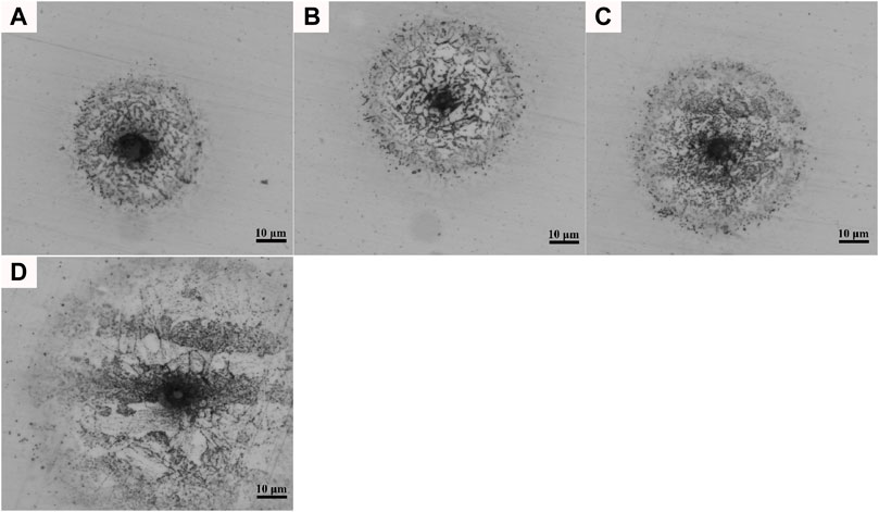
FIGURE 7. Metallography of stable pitting corrosion in the HAZs: (A) CGHAZ; (B) FGHAZ; (C) ICHAZ; (D) BM.
The pitting morphologies of the welded joint in different corrosion stages are presented in Figure 8. As observed in Figures 8A–C, it can be confirmed that the corrosion spots in the WM were scattered in the early stage of corrosion without an obvious single core. With further corrosion, the pits spread uniformly in a circular manner, due to the electromigration of chloride ions (Wang et al., 2021). In addition, dendrite characteristics were obvious in the stable corrosion stage (see Figures 8B,C). The unique pitting core of the HAZ and BM can be observed in Figures 7, 8D–I. The pit nucleus was obviously initiated by an inclusion with a near-spherical shape. Subsequently, the pit continued to develop uniformly around the inclusion, indicating the homogeneous corrosion rate in all directions (Figures 8D–I).
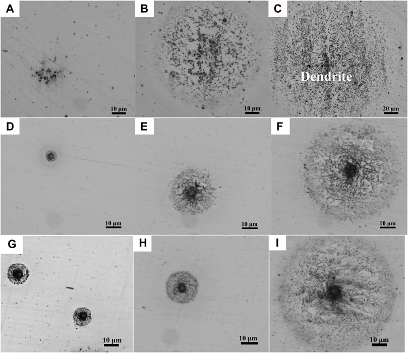
FIGURE 8. OM images of pitting corrosion in different stages: (A–C) WM2; (D–F) FGHAZ; (G–I) BM.
4 Discussion
4.1 Effect of microstructure on the mechanical properties
When the WMmid containing WM3 and WM4 was subjected to the thermal effect of subsequent welding passes, the further diffusion of alloying elements of C, Mn, and Ni from ferrite into austenite occurred, resulting in the dense distribution of MA constituents with a slabby and blocky shape, as shown in Figures 4G-L. There were plenty of mobile dislocations in the ferrite (inset of Figure 9A), which were induced by the volume expansion from austenite to martensite transformation during cooling, leading to continuous yielding behavior or only an inflection point in the tensile curves (Figure 2C) (Zuo and Li, 2015). Table 2 shows that the dendrite spacing of the WMmid was 89.63 μm, which was much smaller than those of the WMin and WMout (142.34 μm and 116.51 μm, respectively). The f of the MA constituents in the WMmid (21.6%) was larger than those in the WMin and WMout (18.0% and 14.3%, respectively), leading to the high hardness, high strength, and low yield ratio of the WMmid (Table 1) (Huda et al., 2016).
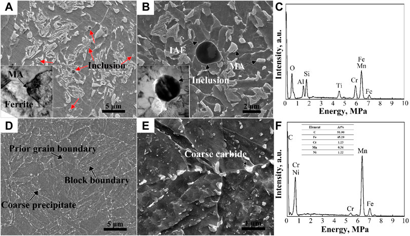
FIGURE 9. SEM morphologies of WM (A,B) and BM (D,E) at different magnification. The corresponding EDS maps of the inclusion (C) and coarse carbide (F) are marked by an arrow in (B) and (E), respectively. TEM bright field images are shown in the insets of (A,B).
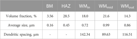
TABLE 2. Average size and volume fraction of the MA constituents in different regions.
As shown in Figures 9A, B, numerous inclusions were found in the WM, regarded as MnO-Al2O3-SiO2-TiO2 type inclusions by EDS (Figure 9C), which were deoxidation products during welding. It is worth noting that this type of inclusion could induce the formation of IAF, as shown in the inset of Figure 9B, whose laths divided the prior austenite grains into small regions, implying the grain refinement (Xiao et al., 2006). This kind of inclusion was also found at the bottom of the dimples (Figures 10A, B, E). Because micro-crevices are prone to occur at the interface between the inclusion and the ferrite matrix under external stress, large amounts of ductile dimples formed both in the fiber region and the shear lip region. Additionally, the dimples were also generated by the deformation incongruity of the MA constituents/polygonal ferrite (Wu et al., 2013; Huda et al., 2016).
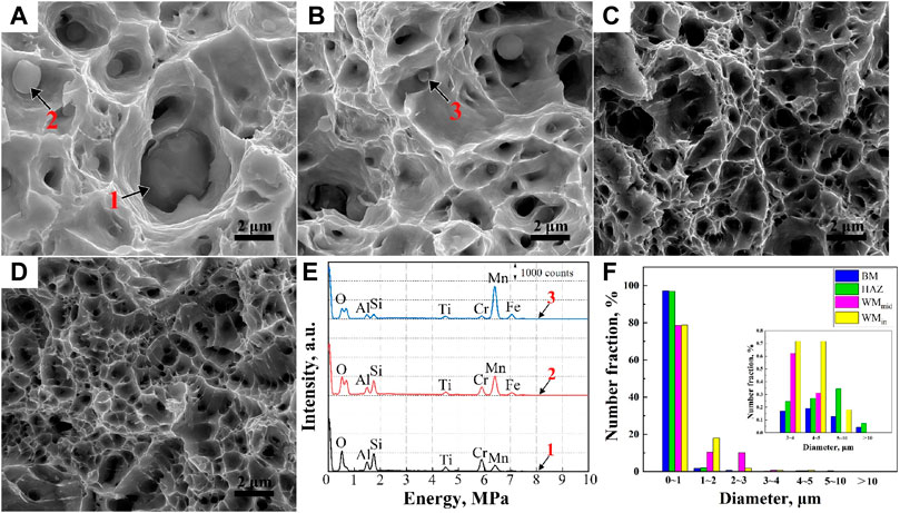
FIGURE 10. Fracture morphologies of the WMin (A), WMmid (B), HAZ (C), and BM (D). The corresponding EDS maps (E) of inclusions are marked by 1, 2, and 3, respectively. The number fraction of the dimples’ diameter in a certain diameter is shown in (F).
Figures 10C, D show that there were only a few inclusions found at the bottom of the dimples in the BM and HAZ. As observed in Figures 9D, E, the BM exhibited a high-temperature tempered martensite microstructure with a large fraction of carbide precipitated mainly in the martensitic packets, block and sub-block boundaries, and prior austenite grain boundaries (PAGBs) (Liu et al., 2015; Pandey et al., 2017; Pandey et al., 2019). The microstructures of the HAZs consisted of fine bainite, ferrite, and MA constituents. It can be deduced that the coarse carbides at the PAGBs of the BM and MA in the HAZ helped the formation of deep dimples. The f of the hard phase of the HAZ was 28.5%, much larger than that of the BM with 3.56%, resulting in the high tensile strength and low yield ratio. In conclusion, from the fracture characteristics of the WM, HAZ, and BM (Figures 3, 10), there were more deep dimples larger than 5 μm in diameter in the BM and HAZ compared to the WMin and WMout, which shows the better plasticity of the BM and HAZ compared to the WM (Konovalenko et al., 2017).
4.2 Formation mechanism of pitting corrosion
4.2.1 Pitting corrosion of the weld
As observed in Figures 11A, B, trench-like pits were generated on the interface of the MA and ferrite at the center of the corrosion pit, which was thought to be owing to the dissolution of the ferrite. However, there were no corrosion pits around the MnO-Al2O3-SiO2-TiO2 inclusions. Therefore, it can be deduced that the MA constituents took precedence over the inclusions of MnO-Al2O3-SiO2-TiO2 in inducing the pitting corrosion. This can be largely explained as follows.
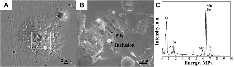
FIGURE 11. SEM morphology of corrosion in WM2 at low (A) and high (B) magnification and the EDS map (C) of the inclusion in (B).
Due to the different solubility limits of the alloying elements (e.g., P, Ni, Cr, Mn, and Mo) solubilized in the ferrite and austenite, the elements’ segregation at ferrite/MA was formed, which generated a large number of dislocations existing near the interface of the MA constituents and ferrite, as displayed in the inset of Figure 9A, further bringing about the higher interface energy and small atomic activation energy (Shibaeva et al., 2014; Kadowaki et al., 2019; Li et al., 2019). Therefore, as shown in Figures 11A, B, the MA constituents acted as cathodic sites inside the anodic ferrite, preferentially generating trench-like pits with the dissolution of the ferrite. Similar results have been obtained in prior studies (Rajput et al., 2020).
The spherical inclusions, confirmed as MnO-Al2O3-SiO2-TiO2-type compound inclusions by EDS in Figure 11C, had good stability and corrosion resistance, and remained intact after immersion, as shown in Figure 11B. Jiang et al. (2015) discovered that MnO-Al2O3-SiO2-TiO2-type compound inclusions were recognized as the combination of TiOx-MnO cores enwrapped by MnO-Al2O3-SiO2 inclusions. Such inclusions contributed to the IAF formation, as mentioned in Section 4.1. The defects at the inclusions/ferrite interface are the key factors for pitting corrosion. TEM analysis was performed to further characterize the inclusion and surrounding IAF, as shown in the inset of Figure 9B. There were few defects (e.g., dislocations, voids) existing in the IAF near the inclusion, so it can be reasonably inferred that MnO-Al2O3-SiO2-TiO2 inclusions surrounded by the IAF hindered the pitting nucleation at the interface between them to a large extent.
As shown in Figure 6, there were scattered pits in WM1, WM3, and WM4, while serious pitting corrosion occurred in WM2 and WM5. Due to the repeated heating of WM1, WM3, and WM4 caused by subsequent passes, the ferrite-forming elements further diffused and homogenized in the ferrite, which continually decreased the ferrite/MA grain boundary segregation, and the residual stress was also released during repeated heating, leading to the good corrosion resistance (Singh et al., 2021). It can be seen from Table 2 that the WMmid-containing WM3 and WM4, with the larger size of the MA constituents and smaller dendrite spacing, had better corrosion resistance compared to the WMin containing WM2 and the WMout containing WM5, as shown in Figures 4, 6. The polarization phenomenon could be formed owing to the micro-galvanic corrosion behavior of the hard MA constituents and ferrite matrix. The rapid diffusion of anions and cations could be achieved by the short pole distance, resulting from the small dendrite spacing of the WMmid, which was equivalent to increasing the electrode reaction interface, further inhibiting the corrosion.
4.2.2 Pitting corrosion of the HAZ
As observed in Figure 6, the corrosion resistance of the HAZ decreased in the sequence of CGHAZ, FGHAZ, and ICHAZ, with the decrease of peak temperature during welding. Furthermore, the pitting corrosion in the HAZ originated from the inclusions, as shown in Figure 12. The inclusions, as the cores of corrosion pits, were identified as Al2O3-MgO-CaO-CaS inclusions by EDS analysis in Figure 12C, and CaS was wrapped in the outer layer of the inclusion due to the segregation of S (Yang et al., 2013). Based on the much higher thermal expansion coefficient of the CaS compared to the ferrite matrix, cavities were formed between them, leading to the adsorption of chloride ions and the initiation of corrosion pits (Wang et al., 2018b; Wang et al., 2021). Therefore, the CaS initially dissolved owing to its higher activity than oxide inclusion, which further decreased the pH of the electrolyte by the CaS chemical dissolution, as shown in Eqs. (1), (2) (Tyurin et al., 2007; Wang et al., 2018b):
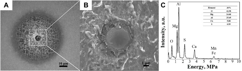
FIGURE 12. SEM morphology of corrosion in the HAZ at low (A) and high (B) magnification and the EDS map (C) of the inclusion in (B).
Wang et al. (2021) and Wranglen (1974) distinguished the inclusions of Ca-Mg-Al-O-S into active and inactive by the CaO/Al2O3 ratios in xCaO-yAl2O3. CaO/Al2O3 ratios below 1.3 were considered as active, while those higher than 1.3 were considered as inactive. The CaO/Al2O3 ratios (R) can be calculated using Eqs. (3), (4) (Wang et al., 2021):
where N is the number of all the atoms; NA is the Avogadro constant (6.02 ×
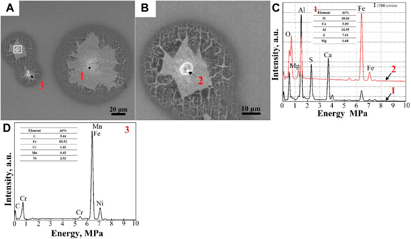
FIGURE 13. SEM morphologies of pit corrosion in the BM (A) and the pit nucleus (B) marked by the white box in (A) at higher magnification. The EDS maps (C,D) of the pit nucleus are marked by 1, 2, and 3.
The various-sized MA constituents in the CGHAZ were densely distributed on the ferrite matrix, possibly causing short-circuit protection. Due to the high peak temperature above Ac3, complete austenitizing had occurred, with much precipitates’ dissolution in the austenite, which led to a decrease in the number of pit initiation sites. Grain refinement can also improve the corrosion resistance of materials (Ma et al., 2018; Rodrigues et al., 2021). Therefore, the microstructure of the FGHAZ with refined grain had no detrimental effect on the corrosion resistance. However, in the ICHAZ, a dual-phase microstructure with obvious band structure was formed, exhibiting serious pitting corrosion. Hence, the corrosion resistance of the ICHAZ was significantly lower than that of the CGHAZ and FGHAZ.
4.2.3 Pitting corrosion of the BM
The corrosion morphology of the BM is shown in Figure 13. The microstructure of the BM was high-temperature tempered martensite with numerous carbides (Figures 9D, E). It can be clearly seen from Figure 13A that the pit nucleus was not unique and can be distinguished into two types: Al2O3-MgO-CaO-CaS inclusion (Figure 13C); and carbide (Figure 13D). The small pit’s nucleus at higher magnification is shown in Figure 13B. It was found that the inclusion was dissolved partly, and the remaining section was regarded as Al2O3-MgO spinel by EDS. A similar phenomenon was reported by Wang et al. (2021), who stated that Al2O3-MgO spinel in (Mg, Al, Ca)-Ox-Sy inclusions would remain after CaS dissolution in EH36 shipbuilding steels. According to Figure 9E, the coarse carbides located at the boundaries were preferable for cathodic reactions to increase corrosion sensitivity (Li and Luo, 2002; Krawiec et al., 2006; Singh et al., 2021). Chloride ions can increase the anodic current density and induce the pitting initiation of plate martensite with M23C6 (M: Cr, Ni, Mn) precipitates (Hu et al., 2011). However, it was difficult to estimate the preferential corrosion between carbides and Al2O3-MgO-CaO-CaS inclusions.
Compared with the corrosion in the WM and HAZ, passive films were clearly observed on the pit corrosion surface of the BM (Figure 13). However, passive films were broken around the pitting core, indicating poor stability, due to Cl ions adsorbed and gathered in the cavities/crevices (Li and Luo, 2002; Talebian et al., 2019). If the fragment falls off, the exposed substrate will be further corroded, greatly deteriorating the corrosion resistance of the material.
5 Conclusion
(1) The microstructure of the WM was proeutectoid ferrite and granular bainite with various-sized MA constituents aggregating into bands. The BM exhibited a high-temperature tempered martensite microstructure with a large fraction of carbide precipitated mainly in the martensite packets, block and lath boundaries, and PAGBs. The microstructures of the HAZs consisted of fine bainite, ferrite, and MA constituents.
(2) The strength and hardness of the welded joint showed a correlation with the f of the MA constituents. The strength and hardness of the WMmid containing WM3 and WM4 were higher than those of the WMin and WMout containing WM2 and WM5 because the f of the MA constituents in the WMmid (21.6%) was higher than those in the WMin and WMout (18.0% and 14.3%, respectively). There were numerous MnO-Al2O3-SiO2-TiO2-type inclusions in the WM, located at the bottom of most dimples. However, there were only a few Al2O3-MgO-CaO-CaS inclusions found at the bottom of dimples in the BM and HAZ. Compared to the fracture characteristics of the WM, the HAZ and BM exhibited numerous deep dimples, indicating the superior plasticity.
(3) In the WM, the MA constituents took precedence over MnO-Al2O3-SiO2-TiO2 inclusions in inducing the pitting corrosion, whereas the pitting corrosion in the HAZ and BM originated from Al2O3-MgO-CaO-CaS inclusions. The corrosion resistance of the welded joint was in the order of WM > HAZ > BM. The WMmid containing WM3 and WM4, with the larger size of MA constituents and the smaller dendrite spacing, had the better corrosion resistance compared to the WMin containing WM2 and the WMout containing WM5. The corrosion resistance of the HAZ decreased in the sequence of CGHAZ, FGHAZ, and ICHAZ with the decrease of peak temperature during welding.
Data availability statement
The original contributions presented in the study are included in the article/supplementary material; further inquiries can be directed to the corresponding author.
Author contributions
YD: writing–original draft, conceptualization, investigation, and experimental validation. DL: investigation and experimental validation. HD: experimental validation. HS: methodology. XZ: writing–review and editing, supervision, conceptualization, and funding acquisition.
Funding
This research was funded by Henan Provincial Science and Technology Cooperation Project China (No. 182106000016) and the Key R&D and Promotion Special Project of Henan Province (No. 212102210444).
Acknowledgments
The authors gratefully acknowledge the financial support provided by Nanjing Iron & Steel Co., Ltd. The funder was not involved in the study design, collection, analysis, interpretation of data, the writing of this article, or the decision to submit it for publication.
Conflict of interest
The authors declare that the research was conducted in the absence of any commercial or financial relationships that could be construed as a potential conflict of interest.
Publisher’s note
All claims expressed in this article are solely those of the authors and do not necessarily represent those of their affiliated organizations, or those of the publisher, the editors, and the reviewers. Any product that may be evaluated in this article, or claim that may be made by its manufacturer, is not guaranteed or endorsed by the publisher.
References
Chatterjee, A., Chakrabarti, D., Moitra, A., Mitra, R., and Bhaduri, A. K. (2014). Effect of normalization temperatures on ductile–brittle transition temperature of a modified 9Cr–1Mo steel. Mat. Sci. Eng. A 618, 219–231. doi:10.1016/j.msea.2014.09.021
Chu, Q. L., Xu, S., Tong, X. W., Li, J., Zhang, M., Yan, F. X., et al. (2020). Comparative study of microstructure and mechanical properties of X80 SAW welds prepared using different wires and heat inputs. J. Mat. Eng. Perform. 29, 4322–4338. doi:10.1007/s11665-020-04986-5
Cui, Z. Y., Liu, Z. Y., Wang, L. W., Li, X. G., Du, C. W., and Wang, X. (2016). Effect of plastic deformation on the electrochemical and stress corrosion cracking behavior of X70 steel in near-neutral pH environment. Mat. Sci. Eng. A 677, 259–273. doi:10.1016/j.msea.2016.09.033
Dong, Y. F., Liu, D. H., Hong, L., Liu, J. J., and Zuo, X. R. (2022). Correlation between microstructure and mechanical properties of welded joint of X70 submarine pipeline steel with heavy wall thickness. Metals 12, 716. doi:10.3390/met12050716
Dong, Z. Q., Li, M., Behnamian, Y., Luo, J. L., Chen, W. X., Amirkhiz, B. S., et al. (2020). Effects of Si, Mn on the corrosion behavior of ferritic–martensitic steels in supercritical water (SCW) environments. Corros. Sci. 166, 108432. doi:10.1016/j.corsci.2020.108432
Fan, Y., Wang, Q. F., and Yang, W. X. (2017). Pitting behavior and mechanism caused by Ca-Al-O-S composite inclusions in low-alloy steels. Anti-Corros. Method M. 64, 218–224. doi:10.1108/ACMM-05-2016-1675
Hu, Y. B., Dong, C. F., Sun, M., Xiao, K., Zhong, P., and Li, X. G. (2011). Effects of solution pH and Cl-on electrochemical behaviour of an Aermet100 ultra-high strength steel in acidic environments. Corros. Sci. 53, 4159–4165. doi:10.1016/j.corsci.2011.08.024
Huda, N., Midawi, A. R. H., Gianetto, J., Lazor, R., and Gerlich, A. P. (2016). Influence of martensite-austenite (MA) on impact toughness of X80 line pipe steels. Mat. Sci. Eng. A 662, 481–491. doi:10.1016/j.msea.2016.03.095
Jiang, M., Wang, X. H., Hu, Z. Y., Wang, K. P., Yang, C. W., and Li, S. R. (2015). Microstructure refinement and mechanical properties improvement by developing IAF on inclusions in Ti–Al complex deoxidized HSLA steel. Mat. Charact. 108, 58–67. doi:10.1016/j.matchar.2015.08.018
Kadowaki, M., Muto, I., Katayama, H., Masuda, H., Sugawara, Y., and Hara, N. (2019). Effectiveness of an intercritical heat-treatment on localized corrosion resistance at the microstructural boundaries of medium-carbon steels. Corros. Sci. 154, 159–177. doi:10.1016/j.corsci.2019.04.019
Konovalenko, I., Maruschak, P., Chausov, M., and Prentkovskis, O. (2017). Fuzzy logic analysis of parameters of dimples of ductile tearing on the digital image of fracture surface. Procedia Eng. 187, 229–234. doi:10.1016/j.proeng.2017.04.369
Kovalov, D., Taylor, C. D., Heinrich, H., and Kelly, R. G. (2022). Operando electrochemical TEM, eEx-situ SEM and atomistic modeling studies of MnS dissolution and its role in triggering pitting corrosion in 304L stainless steel. Corros. Sci. 199, 110184. doi:10.1016/j.corsci.2022.110184
Krawiec, H., Vignal, V., Heintz, O., and Oltra, R. (2006). Influence of the dissolution of MnS inclusions under free corrosion and potentiostatic conditions on the composition of passive films and the electrochemical behaviour of stainless steels. Electrochim. Acta. 51, 3235–3243. doi:10.1016/j.electacta.2005.09.015
Królicka, A., Radwański, K., Kuziak, R., Zygmunt, T., and Ambroziak, A. (2020). Microstructure-based approach to the evaluation of welded joints of bainitic rails designed for high-speed railways. J. Constr. Steel Res. 175, 106372. doi:10.1016/j.jcsr.2020.106372
Kumar, S., Shahi, A. S., Sharma, V., and Malhotra, D. (2021). Effect of welding heat input and post-weld thermal aging on the sensitization and pitting corrosion behavior of AISI 304L stainless steel butt welds. J. Mat. Eng. Perform. 30, 1619–1640. doi:10.1007/s11665-021-05454-4
Li, C. W., Wang, Y., and Chen, Y. H. (2011). Influence of peak temperature during in-service welding of API X70 pipeline steels on microstructure and fracture energy of the reheated coarse grain heat-affected zones. J. Mat. Sci. 46, 6424–6431. doi:10.1007/s10853-011-5592-7
Li, S. C., Guo, C. Y., Hao, L. L., Kang, Y. L., and An, Y. G. (2019). In-situ EBSD study of deformation behaviour of 600 MPa grade dual phase steel during uniaxial tensile tests. Mat. Sci. Eng. A 759, 624–632. doi:10.1016/j.msea.2019.05.083
Li, W. S., and Luo, J. L. (2002). Uniformity of passive films formed on ferrite and martensite by different inorganic inhibitors. Corros. Sci. 44, 1695–1712. doi:10.1016/S0010-938X(01)00178-0
Li, Y. B., Liu, J., Deng, Y. D., Han, X. P., Hu, W. B., and Zhong, C. (2016). Ex situ characterization of metallurgical inclusions in X100 pipeline steel before and after immersion in a neutral pH bicarbonate solution. J. Alloy Compd. 673, 28–37. doi:10.1016/j.jallcom.2016.02.224
Liu, D. H., Dong, Y. F., Li, R. T., Jiang, J. X., Li, X. Y., Wang, Z. L., et al. (2022). Evaluation of mechanical properties and microstructure of X70 pipeline steel with strain-based design. Metals 12, 1616. doi:10.3390/met12101616
Liu, Q., Yang, S. F., Zhao, M. J., Zhu, L. B., and Li, J. S. (2017). Pitting corrosion of steel induced by Al2O3 inclusions. Metals 7, 347. doi:10.3390/met7090347
Liu, W., Liu, X., Lu, F. G., Tang, X. H., Cui, H. C., and Gao, Y. L. (2015). Creep behavior and microstructure evaluation of welded joint in dissimilar modified 9Cr–1Mo steels. Mat. Sci. Eng. A 644, 337–346. doi:10.1016/j.msea.2015.07.068
Ma, G., Zuo, X. R., Hong, L., Ji, Y. L., Dong, J. Y., and Wang, H. H. (2018). Investigation of corrosion behavior of welded joint of X70 pipeline steel for deep sea. Acta Metall. Sin. 54, 527–536. doi:10.11900/0412.1961.2017.00149
Ma, H. C., Liu, Z. Y., Du, C. W., Wang, H. R., Li, X. G., Zhang, D. W., et al. (2015). Stress corrosion cracking of E690 steel as a welded joint in a simulated marine atmosphere containing sulphur dioxide. Corros. Sci. 100, 627–641. doi:10.1016/j.corsci.2015.08.039
Ma, H. C., Zhao, J. B., Fan, Y., Huang, Y. H., Liu, Z. Y., Du, C. W., et al. (2020). Comparative study on corrosion fatigue behaviour of high strength low alloy steel and simulated HAZ microstructures in a simulated marine atmosphere. Int. J. Fatigue. 137, 105666. doi:10.1016/j.ijfatigue.2020.105666
Pandey, C., Mahapatra, M. M., Kumar, P., Kumar, P., Saini, N., Thakare, J. G., et al. (2019). Study on effect of double austenitization treatment on fracture morphology tensile tested nuclear grade P92 steel. Eng. Fail. Anal. 96, 158–167. doi:10.1016/j.engfailanal.2018.09.036
Pandey, C., Mahapatra, M. M., Kumar, P., and Saini, N. (2017). Effect of creep phenomena on room-temperature tensile properties of cast & forged P91 steel. Eng. Fail. Anal. 79, 385–396. doi:10.1016/j.engfailanal.2017.05.025
Poberezhnyi, L., Maruschak, P., Prentkovskis, O., Danyliuk, I., Pyrig, T., and Brezinová, J. (2016). Fatigue and failure of steel of offshore gas pipeline after the laying operation. Arch. Civ. Mech. Eng. 16, 524–536. doi:10.1016/j.acme.2016.03.003
Rajput, A., Ramkumar, J., and Mondal, K. (2020). Effect of pearlitic morphology with varying fineness on the cavitation erosion behavior of eutectoid rail steel. Ultrason. Sonochem. 71, 105399. doi:10.1016/j.ultsonch.2020.105399
Rodrigues, C. A. D., Bandeira, R. M., Duarte, B. B., Tremiliosi-Filho, G., Roche, V., and Jorge, A. M. (2021). The influence of Ni content on the weldability, mechanical, and pitting corrosion properties of a high-nickel-bearing supermartensitic stainless steel. J. Mat. Eng. Perform. 30, 3044–3053. doi:10.1007/s11665-021-05600-y
Shibaeva, T. V., Laurinavichyute, V. K., Tsirlina, G. A., Arsenkin, A. M., and Grigorovich, K. V. (2014). The effect of microstructure and non-metallic inclusions on corrosion behavior of low carbon steel in chloride containing solutions. Corros. Sci. 80, 299–308. doi:10.1016/j.corsci.2013.11.038
Singh, M., Shahi, A. S., and Singh, D. (2021). Influence of heat input on the pitting corrosion and tensile behavior of GTA welded martensitic stainless steel (AISI410 SS) joints. Mat. Today. 46, 10282–10287. doi:10.1016/j.matpr.2020.12.187
Talebian, M., Raeissi, K., Atapour, M., Fernández-Pérez, B. M., Betancor-Abreu, A., Llorente, I., et al. (2019). Pitting corrosion inhibition of 304 stainless steel in NaCl solution by three newly synthesized carboxylic Schiff bases. Corros. Sci. 160, 108130. doi:10.1016/j.corsci.2019.108130
Tyurin, A. G., Pyshmintsev, I. Y., Kostitsyna, I. V., and Zubkova, I. M. (2007). Thermodynamics of chemical and electrochemical stability of corrosion active nonmetal inclusions. Prot. Mater. 43, 34–44. doi:10.1134/S0033173207010043
Wang, L. W., Xin, J. C., Cheng, L. J., Zhao, K., Sun, B. Z., Li, J. R., et al. (2018). Influence of inclusions on initiation of pitting corrosion and stress corrosion cracking of X70 steel in near-neutral pH environment. Corros. Sci. 147, 108–127. doi:10.1016/j.corsci.2018.11.007
Wang, Y. F., Cheng, G. X., Wu, W., and Li, Y. (2018). Role of inclusions in the pitting initiation of pipeline steel and the effect of electron irradiation in SEM. Corros. Sci. 130, 252–260. doi:10.1016/j.corsci.2017.10.029
Wang, Y. H., Zhang, X., Cheng, L., Liu, J., Hou, T. P., and Wu, K. M. (2021). Correlation between active/inactive (Ca, Mg, Al)-Ox-Sy inclusions and localised marine corrosion of EH36 steels. J. Mat. Res. Technol. 13, 2419–2432. doi:10.1016/j.jmrt.2021.06.030
Wang, Y. P., Zuo, X. R., and Li, J. L. (2015). Corrosion resistance of the welded joint of submarine pipeline steel with ferrite plus bainite dual-phase microstructure. Steel Res. Int. 86, 1260–1270. doi:10.1002/srin.201400309
Wranglen, G. (1974). Pitting and sulphide inclusions in steel. Corros. Sci. 14, 331–349. doi:10.1016/S0010-938X(74)80047-8
Wu, B. T., Qiu, Z. J., Pan, Z. X., Carpenter, K., Wang, T., Ding, D. H., et al. (2020). Enhanced interface strength in steel-nickel bimetallic component fabricated using wire arc additive manufacturing with interweaving deposition strategy. J. Mat. Sci. Technol. 52, 226–234. doi:10.1016/j.jmst.2020.04.019
Wu, S. J., Sun, G. J., Ma, Q. S., Shen, Q. Y., and Xu, L. (2013). Influence of QLT treatment on microstructure and mechanical properties of a high nickel steel. J. Mat. Process. Tech. 213, 120–128. doi:10.1016/j.jmatprotec.2012.08.005
Xiao, F. R., Liao, B., Shan, Y. Y., Qiao, G. Y., Zhong, Y., Zhang, C. L., et al. (2006). Challenge of mechanical properties of an acicular ferrite pipeline steel. Mat. Sci. Eng. A 431, 41–52. doi:10.1016/j.msea.2006.05.029
Yang, W., Zhang, L. F., Wang, X. H., Ren, Y., Liu, X. F., and Shan, Q. L. (2013). Characteristics of inclusions in low carbon Al-killed steel during ladle furnace refining and calcium treatment. ISIJ Int. 53, 1401–1410. doi:10.2355/isijinternational.53.1401
Yang, Y. H., Shi, L., Xu, Z., Lu, H. S., Chen, X., and Wang, X. (2015). Fracture toughness of the materials in welded joint of X80 pipeline steel. Eng. Fract. Mech. 148, 337–349. doi:10.1016/j.engfracmech.2015.07.061
Zheng, S. Q., Li, C. Y., Qi, Y. M., Chen, L. Q., and Chen, C. F. (2013). Mechanism of (Mg, Al, Ca)-oxide inclusion-induced pitting corrosion in 316L stainless steel exposed to sulphur environments containing chloride ion. Corros. Sci. 67, 20–31. doi:10.1016/j.corsci.2012.09.044
Keywords: marine steel, welded joint, mechanical properties, MA constituents, pitting corrosion
Citation: Dong Y, Liu D, Du H, Sun H and Zuo X (2023) Effect of microstructure on the mechanical properties and corrosion resistance of a welded joint of 620-grade marine steel. Front. Mater. 10:1107125. doi: 10.3389/fmats.2023.1107125
Received: 24 November 2022; Accepted: 09 January 2023;
Published: 25 January 2023.
Edited by:
Yong A. Zhang, University of Science and Technology Beijing, ChinaReviewed by:
Qiao Yanxin, Jiangsu University of Science and Technology, ChinaPavlo Maruschak, Ternopil Ivan Pului National Technical University, Ukraine
Copyright © 2023 Dong, Liu, Du, Sun and Zuo. This is an open-access article distributed under the terms of the Creative Commons Attribution License (CC BY). The use, distribution or reproduction in other forums is permitted, provided the original author(s) and the copyright owner(s) are credited and that the original publication in this journal is cited, in accordance with accepted academic practice. No use, distribution or reproduction is permitted which does not comply with these terms.
*Correspondence: Xiurong Zuo, enVveGl1cm9uZ0B6enUuZWR1LmNu