
94% of researchers rate our articles as excellent or good
Learn more about the work of our research integrity team to safeguard the quality of each article we publish.
Find out more
ORIGINAL RESEARCH article
Front. Mater. , 31 August 2022
Sec. Structural Materials
Volume 9 - 2022 | https://doi.org/10.3389/fmats.2022.991584
 Jing Ji1,2
 Yunhao Li1Liangqin Jiang1,2*Hongguo Ren3*Qingqin Wang4Lei Zhang3*Lingjie He1Zhanbin Zhang1
Honeycombed beams are widely used because they are conducive to the layout of pipelines and circuits, and the traditional honeycombed beams are generally H-shaped steel beams and concrete-encased upper flange composite beams. In this paper, a composite beam with concrete-filled steel tube as both upper and lower flanges and steel plate with circular openings as web is proposed. The effective constraint of steel tube on concrete strengthens the deformation ability of concrete. In order to study the flexural behavior of composite beams with concrete filled steel tube flanges and honeycombed steel webs (SHC), 25 simply-supported SHC beams were designed to carry out the four-point bending load simulation analysis. By reasonable modeling method. The main parameters of SHC concluding the compression strength of concrete (fck), yield strength of steel (fyfk), height-to-span ratio (H/L), ratio of space to height of web (s/hw), thickness of steel tube flange (t1), thickness of web (t2) and ratio of hole to height of web (a/hw) were discussed, and the whole loading process of the beam was analyzed. The results showed that the SHC specimens could be divided into elastic stage, elastic-plastic stage and plastic stage under four-point bending load. Steel tube in the tensile zone yielded firstly before specimens failed, and the failure mode of the specimens was that the concrete at the loading point was crushed. Though the steel tube in lower flange at the support, loading point and mid-span yielded, the web did not buckle. SHC could meet the requirements of Chinese code in the normal use stage, and the cross-section deformation basically conformed to the plane assumption. Finally, based on the unified strength theory, a prediction formula of ultimate bending moment is established, which is in good agreement with experiment and can lay the foundation for the popularization and application of this kind of beams.
With the increasing of height for buildings, the traditional steel structure is prone to buckling instability, and will produce large vibration under the actions of earthquake and strong wind, which can affect comfort and not meet the needs of engineering projects. At present, the combination with new materials and new structural forms, such as the organization between FRP, concrete with high ductility and steel tube with high strength, multi-web structure, can make the members greatly play the advantages of materials, which can be widely used in the architectures (Ekmektapar and Al-Eliwi, 2017; Afshar et al., 2020; Alajarmeh et al., 2021; Cai et al., 2021; Lepcha and Patton, 2021; Vedernikov et al., 2022). With the continuous development of science and technology, wide flange steel has emerged. Honeycombed steel beams have begun to be widely used in bridges, factories, crane bridges and other projects, which can reduce the use of steel by 45%, and the cross-sectional height of honeycombed beams after opening can be increased by 1.2–1.7 (Raut et al., 2020). As the height of cross section increased, the moment of inertia and resistance of cross section increased, so the stiffness and strength of beams could be improved (Ji et al., 2021a). Based on this research, a new type of assembled frame structure composed of the composite beams and columns with rectangular concrete filled steel tube flanges and honeycombed steel web was proposed. The composite columns and beams with concrete filled rectangular steel tube flanges had large stiffness, good stability and were not prone to structural stability, and the external steel tube could effectively restrict the deformation of internal concrete to prevent brittle failure of concrete (Ji et al., 2017; Ji et al., 2018a; Ji et al., 2018b; Ji et al., 2021b; Ji et al., 2022). The honeycombed steel web can reduce the weight of structure, and the pipeline system can be arranged through the honeycomb to make the building structure more aesthetically pleasing. The new frame system with many advantages will be widely used in high-rise buildings and bridges (Shao et al., 2020).
The research on mechanical properties of beam with concrete filled steel tubular flange and honeycombed beams has always been a new hot topic at home and abroad. The flexural experiments of three beams with rectangular steel tube flanges under concentrated loading at mid-span were carried out by (Ren., 2015), and the failure modes of three sections were studied. According to the different positions of neutral axis, the theoretical calculation formulas of elastic and plastic flexural capacity of four different sections were deduced. Three-point bending experiments were carried out on five concrete beams with rectangular steel tube upper flange by (Fu, 2016). It was found that the deformation curves of the composite beams were half-wave sine curves, and the composite beams with smaller height-width ratio of upper flanges and higher web had larger greater flexural capacity. The composite beams with large sectional size were prone to buckling at the top of the upper flange. Three honeycombed beams with rectangular concrete filled steel tube upper flanges were tested by (Tan, 2017). The results showed that the bearing capacity and out-of-plane stiffness of the beams could be improved by increasing the width of upper flange. The stiffness of the upper flanges should not be too large, otherwise distortional buckling would occur easily in the mid-span. During the process of instability for beams, the stress around the hole is the most concentrated. The numerical simulations of end-plate connection between full-scale columns and honeycombed beams were performed by (Madjour et al., 2018). It was determined that the end-plate connection could improve the overall flexural and shear capacity of honeycombed beams with circular and sinusoidal web openings. The test and simulation analysis of the full-scale steel honeycombed beams were carried out by (Grilo et al., 2018), and based on the resistance curves, a new formula was proposed to calculate the shear resistance in the beams when the web was buckled. The tests on the bearing capacity of honeycombed beams under negative bending moment were carried out by (Ma et al.,2019), and the results showed that the expansion ratio and spacing of holes have great influences on the strength of beams. When the expansion ratio increased from 1.2 to 1.3, the strength of the composite beams increased by 53.5% and the stiffness increased by 49.3%. The finite element analysis of elastic and inelastic buckling of honeycombed beams under strong axial bending were carried out by (Rajana et al., 2020). It was found that the thickness of web and the geometric shape of flange have the greatest influence on the flexural behavior of this kind of beams (Felipe et al., 2021). The I-shaped composite beams with rectangular concrete filled steel tube flanges and honeycombed steel web are further studied on the basis of honeycombed steel beams and concrete filled steel tube beams, which can better play the advantages of both and achieve maximum benefit. At present, there are few studies on this kind of composite beams in China and foreign countries, and there is a lack of relevant structural design and construction specifications. Therefore, the research on the flexural bearing capacity of such composite beams has theoretical significance and practical value.
Based on the finite element software ABAQUS, the flexural behavior of 25 SHC composite beams were analyzed in this paper, and the main parameters included the compression strength of concrete (fck), yield strength of steel (fyfk), height-to-span ratio (H/L), ratio of space to height of web (s/hw), thickness of steel tube flange (t1), thickness of web (t2) and ratio of hole to height of web (a/hw). The finite element models of full-scale SHC composite beams were established rationally, and the four-point flexural performance analysis of this kind of beams were carried out. The load-displacement curves, load-strain curves and failure modes of the composite beams could be obtained, and the influences of different parameters on the flexural capacity of SHC composite beams were analyzed. The calculation formula for the flexural capacity of the composite beams could be statistically regressed, which could give important theoretical significance and engineering practical for its popularization and application.
25 composite beams with concrete filled steel tube flanges and honeycombed steel web (SHC) were designed, including the main controlled parameters as the compression strength of concrete (fck), yield strength of steel (fyfk), height-to-span ratio (H/L), ratio of space to height of web (s/hw), thickness of steel tube flange (t1), thickness of web (t2) and ratio of hole to height of web (a/hw), as shown in Table 1. All specimens with a sectional size (b×H) of 400 mm × 800 mm. The stiffeners with a thickness of 16 mm were arranged at the position of L/3, 2L/3 and two ends of SHC beams, and the strength of steel was the same as that of beam and steel tube. The schematic and sectional sizes of SHC are shown in Figure 1.

TABLE 1. The main parameters of 25 specimens.

FIGURE 1. SHC and the local dimensions. (A)The composition of SHC (B)The sectional size of SHC and steel web.
The ideal double-broken line model (Han, 2007) was adopted as the elastic-plastic constitutive model of the steel tube flanges and honeycombed steel web, as shown in Figure 2 εy and fy were the yield strain and yield strength of steel, respectively.

FIGURE 2. Constitutive model of steel tube flanges and steel webs.
Concrete is a kind of heterogeneous materials with complex mechanical properties. The influence of plastic damage on concrete was considered in the ABAQUS software. Through comparing the proposed constitutive models of concrete considering constraint effect proposed by (Teng et al.,2007; Mander et al.,1988; Han and Tao, 2001; Pagoulatou et al.,2014), the constitutive model of confined concrete proposed by Han was adopted. The comparisons of constitutive models for concrete are shown in Figure 3, and material parameters are shown in Table 2.
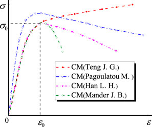
FIGURE 3. The comparison of different constitutive models of concrete.

TABLE 2. Material parameters of concrete.
The stress-strain relationship of concrete under uniaxial compression:
Where fc is compressive strength of concrete. ξ is constraint effect coefficient of concrete. σ0 is peak tensile stress. ε0 is peak tensile strain. β0 reflects the ductility and energy absorption of concrete.
The stress-strain relationship of concrete under uniaxial tension:
Where σp is peak tensile stress. εp is peak tensile strain.
The FEM of SHC was established based on ABAQUS software. The concrete, steel tube flanges, honeycombed web, and stiffeners were established by C3D8R solid element, and the interaction between concrete and steel tube adopted binding, and slabs and stiffeners were bonded to steel tubes (Liu, 2005; Dai and Lam, 2010; Ji et al., 2019; Ji et al., 2021b). In order to avoid stress concentration at the loading point, rigid slabs were set at the ends of beams and three-point loading positions. The reference points (RP1 and RP2) were set at an axial distance of 10 mm from the three-point of beams, and coupled with slabs. The displacements of RP3 was constrained in X, Y and Z directions (U1 = U2 = U3 = 0), and the displacement of RP4 was constrained in Y and Z directions (U2 = U3 = 0). Hexahedral element was used for the mesh generation. In order to obtain the optimal meshing, the specimens selected from the references (Fu, 2016; Yu et al., 2018) were simulated. A variety of size grids were used for comparisons, as shown in Figure 4, and it could be found that the mesh size of 80 mm was more reasonable. The finite element model of SHC composite beams was shown in Figure 5.

FIGURE 4. Comparisons of different mesh sizes for existing specimens. (A) Comparisons of different mesh sizes for specimens by Fu Y. (B) Comparisons of different mesh sizes for specimens by Yu C.J.
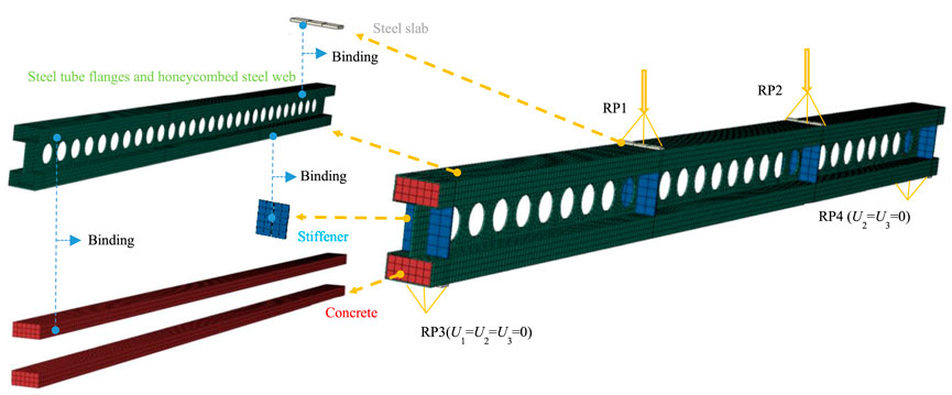
FIGURE 5. Meshing and boundary conditions of SHC.
In order to verify the rationality of the finite element modeling, the above modeling method was adopted. Five beams with rectangular concrete-filled steel tube flanges by (Fu, 2016), one beam with circular concrete-filled steel tube flanges by (Wang et al., 2008), seven beams with rectangular concrete-filled steel tubes by (Yu et al., 2018) and six beams with rectangular concrete-filled steel tubes by (Liu and Wu, 2010) were analyzed by finite element simulation. The specific parameters of specimens were shown in Table 3.
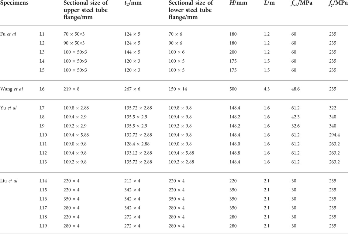
TABLE 3. The specific parameters of 19 existing specimens.
By finite element simulation, the load-displacement curves of the simply-supported beams could be obtained, and the comparisons of load-displacement curves between experiments and simulations were shown in Figure 6. It could be seen by comparisons that the load-displacement curves obtained by simulations and experiments were in good agreement, and the rationality of the finite element modeling was verified. The comparative results of the ultimate bearing capacity (
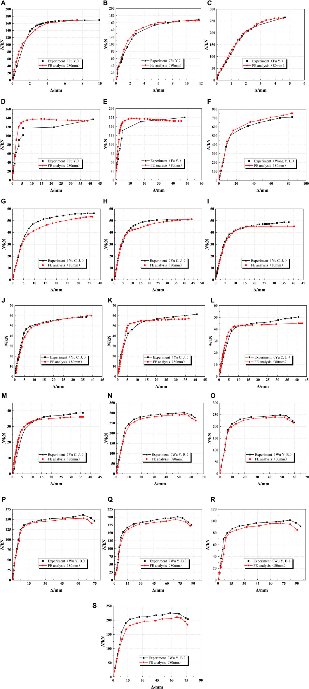
FIGURE 6. Comparisons between simulated curves and experimental curves (A)L1 (B) L2 (C) L3 (D) L4 (E) L5 (F) L6 (G) L7 (H) L8 (I) L9 (J) L10 (K) L11 (L) L12 (M) L13 (N) L14 (O) L15 (P) L16 (Q) L17 (R) L18 (S) L19.

FIGURE 7. Comparisons between
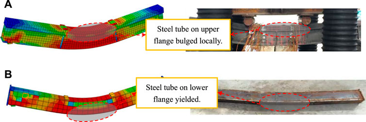
FIGURE 8. Failure modes of L2 and L10 specimens (A) L2 was crushed (B)The steel tube of L10 yielded.
In order to understand the change of material strength and the influence of geometric relationship on the flexural behavior of beams, 25 specimens with different parameters (fck, fyfk, t1, t2, a/hw, s/hw and H/L) were compared and analyzed. The specific information is shown in Figure 9.
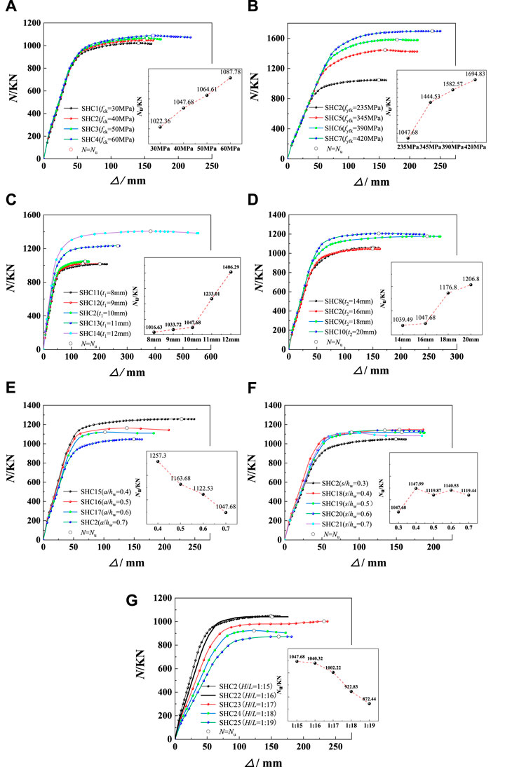
FIGURE 9. Comparisons of load-displacement curves for 25 SHC. (A) SHC with different fck (B) SHC with different fyfk (C) SHC with different t1 (D) SHC with different t2 (E) SHC with different a/hw (F) SHC with different s/hw (G) SHC with different H/L.
The load-displacement curves of specimens with different fck are shown in Figure 9A, It could be seen that when fck increased from 30 to 60MPa, ultimate flexural bearing capacity (Nu) increased from 1,022.36 KN to 1,087.78KN, which increased only by 6.40%. And the corresponding mid-span displacement (ΔNu) increased from 140.83 to 162.54mm, by 15.41%. It could illustrate that fck had no obvious influence on the ultimate flexural behavior of beams.
It could be seen from Figure 9B that the load-displacement curves of each specimen had the same trend, but the ultimate bearing capacity varied greatly. When fyfk increased from 235 to 420 MPa, Nu increased from 1,047.68 KN to 1,694.83 KN, by 65.78%. Meanwhile, ΔNu increased from 149.39 to 236.94 mm, by 58.60%.Therefore, Nu could be effectively improved by increasing fyfk, Moreover, the deformation ability was improved under peak load.
As shown in Figure 9C, when t1 increased from 8 to 9 mm, 10 mm in turn, Nu increased the most only by 3.05%, and with the change of that t1 increased from 8 to 11mm and 12 mm in turn, Nu increased from 1,016.63 KN to 1,233.01 KN and 1,406.29KN, respectively, which increased by 21.28 and 38.33%. It could be found that ΔNu basically increased with the increase of t1. When t1 changed from 8 to 10 mm, ΔNu increased by 80.67%. When t1 exceeded 10 mm, Nu was improved most obviously.
It could be seen from Figure 9D that when t2 increased from 14 to 16, 18 and 20 mm in turn, Nu increased from 1,039.49 KN to 1,047.68, 1176.80 and 1,206.80 KN, respectively, which increased by 0.8, 13.2 and 16.1%, and ΔNu increased from 150.05 to 149.39, 246.95 and 160.43 mm, respectively, by −0.44, 64.57 and 6.91%. This meant that the web could provide a part of the bending strength of the beam, resulting in higher Nu, and t2 had no obvious influence on ΔNu.
The opening size and spacing of the web have an impact on the flexural behavior of the beam. It could be seen from Figures 9E,F that when a/hw increased from 0.4 to 0.7, Nu decreased from 1,257.30 KN to 1,047.68 KN, which decreased by 16.67%, and ΔNu decreased by 39.61, 55.37 and 34.55%.
When s/hw increased from 0.3 to 0.4, 0.5, 0.6 and 0.7 in turn, Nu changed from 1,047.68 KN to 1,147.99, 1119.87, 1140.53 and 1,119.44KN, respectively, which increases by 9.57, 6.89, 8.86 and 6.85%, while ΔNu changed by 3.25%, 5.37%, −9.92% and −39.86%, respectively, without showing obvious regularity. This showed that the opening on the web would weaken the flexural behavior of the beam. Moreover, with the increase of a/hw, the deformation capacity at peak load decreased. In contrast, the larger the opening spacing was, the better the flexural behavior of the beam was, but the impact was relatively small.
When H/L increased from 1:15 to 1:16, 1:17, 1:18 and 1:19 in turn, as shown in Figure 9G, Nu decreased from 1,047.68 KN to 1,040.32, 1002.22, 922.83 and 872.44 KN, respectively, which decreased by 0.7, 4.34, 11.92 and 16.7%, and ΔNu changed from 149.39 mm to 231.98, 122.92, 161.36 and 151.18 mm, showing no obvious regularity. It could be found that when H/L was between 1:15 and 1:16, it had little effect on Nu, but with the further increasing of H/L, the weakening effect on the flexural behavior was obviously enhanced.
The 25 specimens with different parameters were divided into 7 groups. K and µ were compared and analyzed. µ was calculated by the energy equivalent method, which was shown in Formula Eq. 8 and Figure 10. The results of K and μ were shown in Table 4.
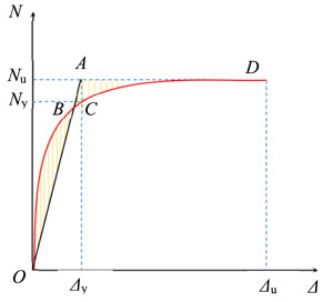
FIGURE 10. Energy equivalence method.
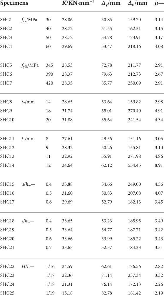
TABLE 4. K and µ for SHC with different parameters.
where Δy and Δu were the yield displacement and ultimate displacement, respectively.
Due that the composite beam is a non-ideal elastic-plastic body, it is impossible to find Δu from the load-displacement curve, and the ultimate displacement of the load-displacement curve is taken as Δu (Hu et al., 2020).
As shown in Figure 11 and Table 4, it was easy to find that the K and µ of the specimens showed different laws with different variables. K is related to elastic modulus and section form (Al et al., 2020), and the improvement of concrete strength can increase the elastic modulus of the beam. However, compared with the specimen with fck = 30 MPa, the K of the specimen with fck = 60 MPa was only raised by 5.81%. The elastic modulus of steel with different fyfk changed little, so the K of SHC5∼SHC7 specimens were similar. When t1 changed from 8 to 12 mm, K increased by 25.47%. When t2 changed from 14 to 20 mm, K increased by 11.27%. The cross-sectional area of steel could be improved with the increase of t1 and t2, which is conducive to raising the elastic modulus of the beam and indirectly improving K. In addition, when a/hw increased from 0.4 to 0.7, K reduced by 15.23%. The opening on the web could reduce the steel section area of the web, so K decreased with the increase of a/hw. When H/L increased from 1:15 to 1:19 in turn, K decreased by 47.14% from 28.72 kN mm−1 to 15.18 kN mm−1, which indicates that the weakening effect of H/L on K was extremely obvious.

FIGURE 11. K and µ of 25 SHC specimens with different parameters.
Notably, µ of specimens with different fck (SHC1∼SHC4) increased from 3.14 to 3.15, 3.17 and 4.08, by 0.32, 0.95 and 29.94%, respectively. When fck = 60 MPa, µ changed sharply. It might be that the high-strength concrete of the steel tube flange had better compressive performance, and the concrete in the compression zone was destroyed later. Besides, the interaction between the confined high-strength concrete and the steel tube was more coordinated, resulting in a significant improvement in µ (Yao and Xiong, 2018). The steel web and steel tube in the beam also had great influence on the deformation ability of the beam. When t2 changed from 14 to 20 mm, μ increased from 2.98 to 3.15, 4.91 and 4.34, by 5.70%, 64.76 and 45.63%, respectively. It is showed that t2 could significantly improve the deformation behavior of beams. Compared with all factors, µ had a great enhancement by the increase of t1. When t1 changed from 8 to 12 mm, μ increased by 192.13%. In addition, the opening of the web could also affect µ, such as a/hw and s/hw. When a/hw increased from 0.4 to 0.7, the greater the a/hw was, the more seriously the deformation capacity of the beam was weakened. When s/hw increased from 0.3 to 0.4, μ increased from 3.15 to 3.49, by 10.79%. However, when s/hw continued to increase to 0.7, μ basically did not increase significantly. The reason was that when the opening spacing was less than 0.4, due to the excessive density of holes, the “softening” phenomenon occurred in the web, and prone to yield. Therefore, the ductility could be improved with the increase of s/hw. When s/hw reached a certain degree, the improvement of the ductility of the beam could tend to a stable state (Liu, 2013). Finally, when the cross section of the beam was determined and the length of the beam was larger, the trend of μ was basically reduced, and the bending deformation ability was weakened obviously.
The SHC specimen could be divided into elastic stage, elastic-plastic stage and plastic stage under four-point bending load, as shown in Figure 12. In the elastic segment (N ≤ Ny), the deformation of the beam was small. Except that the steel tube on the lower flange at the support was close to the yield stress, the specimen was in the elastic deformation stage. When the specimen entered the elastic-plastic segment (Ny < N ≤ Nu), the steel tube on the lower flange at the mid-span position and the steel tube at the loading point gradually reached the yield stress, and the concrete at the upper and lower flange began to crack. With the further increase of deflection, the specimen entered the plastic stage (N ˜ Nu), and the specimen could stably maintain the ultimate load, and the deflection was also improved rapidly. Finally, the concrete on the upper flange at the loading point was crushed and the specimen was destroyed.
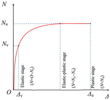
FIGURE 12. The whole process of SHC.
The finite element models of specimen SHC2 was used as a typical specimen to describe failure mode of this kind beams. It could be seen from Figures 13A,B that after the failure of specimen SHC2, although the lower steel tube flange exhibited buckling deformation, the encased concrete almost kept good performance, and the upper concrete at four-point loading position was crushed. Due to the increasing in cross-sectional height and the setting of stiffeners at the web, the SHC composite beams would not appear lateral instability, and there was no local buckling around the opening in the web.
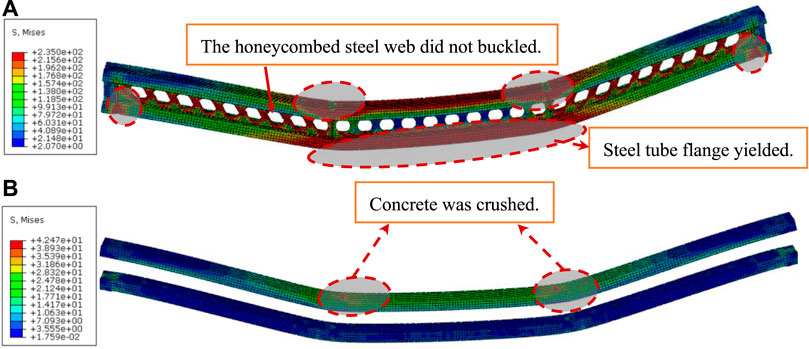
FIGURE 13. The stress cloud of SHC. (A) The stress cloud of steel tube flange of SHC2 (B) The stress cloud of concrete of SHC2.
The load-strain curves of steel and concrete for typical specimens were shown in Figure 14. It was not difficult to find that at the beginning of loading, the steel and concrete maintained elastic deformation, and the relationship between load and strain was basically linear. Under the load of 0.70Nu∼0.86Nu, the steel in the tension zone firstly yielded, and then the concrete in the tension zone began to crack, and finally the concrete in the compression zone was crushed, and the upper steel yielded. However, it was found in Figures 14F–H that the concrete in the tensile zone was firstly destroyed, and then the steel in the tensile zone yielded or the concrete in the tensile zone was crushed. The main reason was that Q345, Q390 and Q420 were adopted for steel, and the concrete in SHC reached the compressive strength and tensile strength before the steel yielded.
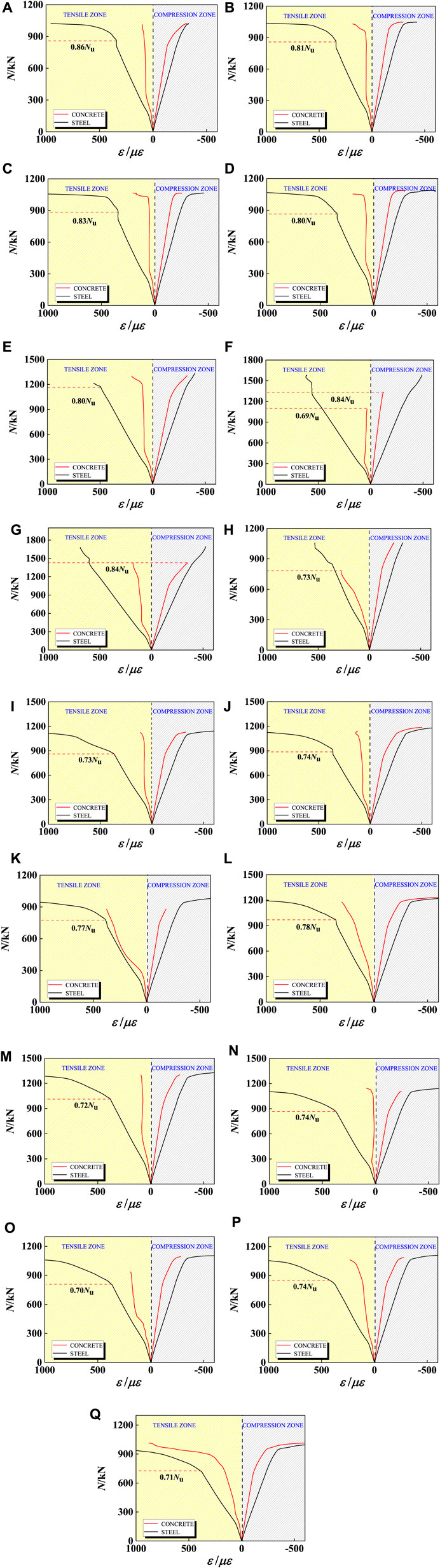
FIGURE 14. Load-strain curves of concrete and steel tube: (A) SHC1; (B) SHC2; (C) SHC3; (D) SHC4; (E) SHC5; (F) SHC6; (G) SHC7; (H) SHC8; (I) SHC9; (J) SHC10; (K) SHC11; (L) SHC13; (M) SHC14; (N) SHC16; (O) SHC18; (P) SHC19; (Q) SHC23.
Deflection curves of all specimens were basically symmetrically distributed under the action of four-point loading. The deflection deformation curves of SHC2, as shown in Figure 15A, was approximately sinusoidal. Moreover, the maximum deflection appeared in the mid-span of SHC composite beams. When the specimen was in normal use stage (N < 0.6Nu), the mid-span deflection was only 0.002L, which could meet the limit L/300 of practical engineering requirements (GB 50010–2010, 2010). When the load reached above 0.91Nu, the deflection deformation speed of the specimens increased continuously, and finally the plastic hinge appeared in the mid-span of the composite beams. With the continuous increase of loading, the load that was borne by the tensile zone of steel tube increased continuously, and the steel tube in the tensile zone buckled, finally the SHC composite beam was destroyed. According to Figure 15B, the span(L) had a great influence on the deflection of beams, and L was proportional to deflection. In addition, under the action of four-point bending load, When the ultimate flexural capacity is reached, the deflection range of SHC is between 0.012 and 0.018L, 3–6 times as the bending deflection limit in Chinese code, which indicated that SHC could have good deformation performance.
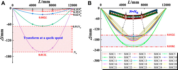
FIGURE 15. Analysis for deflection of SHC. (A) Deflection distribution of SHC2 (B) Deflection distribution of 25 specimens.
It could be seen from Figure 16 that at the initial stage of loading, the longitudinal strain of the mid-span section was basically linear. The steel tube and concrete worked together, so the composite beam had higher flexural bearing capacity. In the elastic working stage, the longitudinal deformation of the mid-span section for SHC composite beams was consistent with the plane section assumption. At the end of loading, when the load was above 0.89 times as the ultimate bearing capacity, the neutral axis began to move upward, but basically in the area of web. The longitudinal strain along the height direction basically present a linear relationship. The concrete of the upper flange was crushed, and the steel tube on the lower flange buckled, which meant both failed corporately. During the whole process of loading, the strain in tensile zone was greater than that in the compression zone.
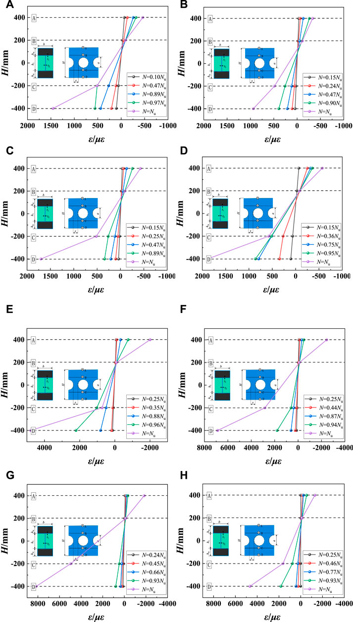
FIGURE 16. Longitudinal strain distribution along the height of mid-span section. (A) SHC1 (B) SHC2 (C) SHC3 (D) SHC4 (E) SHC11 (F) SHC12 (G) SHC17 (H) SHC20.
In this paper, the following basic assumptions were adopted: 1) Plane section assumption. 2) Both steel and concrete were isotropic elastomers. 3) There was no slip between steel tube and concrete. 4) There is no strengthening stage of steel tube material. 5) The concrete in the tensile zone does not consider the tensile effect, and the stress diagram of concrete in the compression zone is rectangular.
Concrete-filled steel tube structures have high bearing capacity, and the plasticity and toughness are good. It can prevent external steel tube buckling by filling concrete in the steel tube. The steel tube increases the constraint effect on the internal concrete and increases the crack resistance of the concrete, so that the bearing capacity of the concrete-filled steel tube beams is higher than that of the steel tube and concrete.
A unified theory of steel tube that regarded concrete-filled steel tube as a unified whole was proposed by (Zhong, 1994). The design value of the composite strength for rectangular concrete-filled steel tube was shown in Formula Eq. 9.
Where
The calculation diagram of the neutral axis for the web of composite beams was shown in Figure 17. According to the plane section assumption, it could be obtained that:
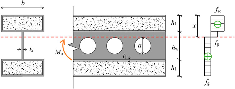
FIGURE 17. Calculation diagram of composite beams.
The resultant force of each part was:
Where, Fsc was the resultant force of rectangular concrete-filled steel tube in compression zone. Ftc was the resultant force generated by the web in compression zone. Ftt was the resultant force generated by the web in tension zone. Fxt was the resultant force of steel tube in tension zone. fsc was axial compressive strength of rectangular concrete-filled steel tube. fg was yield strength of steel tube and web. x was distance from the top of beam to neutral axis. b was width of rectangular concrete-filled steel tube. h1 was height of rectangular concrete-filled steel tube. hw was depth of web. A was height of opening. T1 was thickness of steel tube. T2 was thickness of web.
According to the balance of sectional force, Fsc + Ftc = Ftt + Fxt. x could be obtained. The bending moments of each part were shown in Formula Eqs. 12–15.
Where Msc was the bending moment generated by rectangular concrete-filled steel tube in compression zone. Mtc was the bending moment generated by the web in compression zone. Mtt was the bending moment generated by the web in tension zone. Mxt was the bending moment generated by steel tube in tension zone.
According to the balance of the sectional moment, the flexural bearing capacity of composite beams could be obtained by Formula Eq. 16.
The calculation results of the bearing capacity for 25 full-scale SHC composite beams were shown in Table 5. It could be found that the calculated bearing capacity (
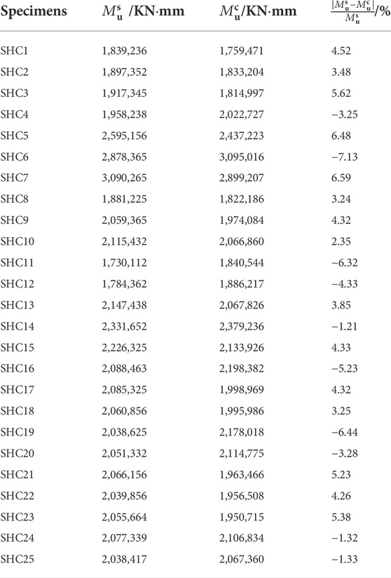
TABLE 5. Comparison between
In order to study the flexural behavior of SHC composite columns, a series of numerical analysis for 25 SHC specimens with different parameters were carried out based on ABAQUS software. The results were as follows:
1) The influences of fck and s/hw on the flexural behavior of the beam were not obvious, but the flexural behavior of the beam could be effectively improved by increasing the steel strength of the flange and the web, the thickness of steel tube and the web, Moreover, the deformation ability of the beams at peak load can be significantly improved with the increase of fyfk and t1. When fyfk changed from 235 to 420 MPa, Nu increased by 65.78%. When t1 increased from 8 to 12 mm, μ increased by 192.13%. In addition, a/hw and H/L had obvious weakening effect on the flexural behavior of the beam, and when a/hw changed from 0.4 to 0.7, Nu, K and μ reduced by 16.67, 15.23 and 30.92%, respectively.
2) Under four-point bending load, SHC specimens could be divided into elastic stage, elastic-plastic stage and plastic stage. Steel tube in the tensile zone yielded firstly before specimens failed, and the failure mode of the specimens was that the concrete at the loading point was crushed. The steel tube in lower flange at the support, loading point and mid-span yielded, but the web did not buckle. The deflection of SHC beam could meet the requirements of Chinese code in the normal use stage, and the ultimate deflection could reach 3–6 times as the normal use deflection, and the deformation ability was good.
3) This kind of beams basically conformed to the plane section assumption. Based on the unified strength theory, a prediction formula of ultimate bending moment was established, which was in good agreement with experiment and could lay the foundation for the popularization and application.
In this paper, the flexural behavior of the composite beams with concrete-filled rectangular steel tube flange and honeycomb steel web has been analyzed by simulation and theoretical research. It is found that the composite beam with concrete-filled rectangular steel tube flange and honeycomb steel web has the advantages of good flexural behavior and large deformation capacity. However, it is urgent to carry out further and in-depth research on such composite beams by combining experiment and finite element method. In addition, only the composite beam is studied in this paper, and the frame structure system composed of columns and joints matching with such composite beams needs to be studied further. Under the background of increasingly mature composite materials and high-performance materials, better mechanical properties may be obtained by pouring new materials such as concrete with high ductility into composite columns and replacing steel tubes with FRP, which needs further study.
The original contributions presented in the study are included in the article/Supplementary Material, further inquiries can be directed to the corresponding authors.
JJ: Finite element simulation, writing; YL: Finite element simulation, writing; LJ: translation, writing; HR: writing; QW: writing; LZ: writing; LH: translation; ZZ: writing. All authors contributed to the article and approved the submitted version.
The research described in this paper was financially supported by General Project of National Natural Science Foundation of China (grant no. 52178143), Joint Guidance Project of Natural Science Foundation of Heilongjiang Province (grant no. LH 2020E018), China-Pakistan Belt and Road Joint Laboratory on Smart Disaster Prevention of Major Infrastructures (grant no. 2022CPBRJL-05), 2021 Social Science Development Research Project of Hebei Province (grant no. 20210301135), Humanities and Social Science Research Project of Higher Education Institutions of Hebei Province (grant no. SQ2021115) Guiding Science and Technology Project of Daqing City (grant no. zd-2021-40) and The Guided Innovation Fund of Northeast Petroleum University (grant no. 2020YDL-02).
QW was employed by China Academy of Building Research Co., Ltd.
The remaining authors declare that the research was conducted in the absence of any commercial or financial relationships that could be construed as a potential conflict of interest.
All claims expressed in this article are solely those of the authors and do not necessarily represent those of their affiliated organizations, or those of the publisher, the editors and the reviewers. Any product that may be evaluated in this article, or claim that may be made by its manufacturer, is not guaranteed or endorsed by the publisher.
50010GB -2010, 201050010GB -2010 (2010). Code for design of concrete structures. Beijing: China Construction Industry Press.
Afshar, A., Jahandari, S., Rasekh, H., Shariati, M., Afshar, A., and Shokrgozar, A. (2020). Corrosion resistance evaluation of rebars with various primers and coatings in concrete modified with different additives. Constr. Build. Mater. 262, 120034. doi:10.1016/j.conbuildmat.2020.120034
Al, Z. A. W., Badaruzzaman, W. H. W., and Tawfeeq, W. M. (2020). New empirical methods for predicting flexural capacity and stiffness of CFST beam. J. Constr. Steel Res. 164, 105778. doi:10.1016/j.jcsr.2019.105778
Alajarmeh, O., Zeng, X. S., Aravinthan, T., Shelley, T., Alhawamdeh, M., Mohammed, A., et al. (2021). Compressive behaviour of hollow box pultruded FRP columns with continuous-wound fibres. Thin-Walled Struct. 168, 108300. doi:10.1016/j.tws.2021.108300
Cai, Z. W., Liu, F. C., Yu, J. T., Yu, K. Q., and Tian, L. K. (2021). Development of ultra-high ductility engineered cementitious composites as a novel and resilient fireproof coating. Constr. Build. Mater. 288, 123090. doi:10.1016/j.conbuildmat.2021.123090
Dai, X., and Lam, D. (2010). Numerical modelling of the axial compressive behaviour of short concrete-filled elliptical steel columns. J. Constr. Steel Res. 66, 931–942. doi:10.1016/j.jcsr.2010.02.003
Ekmekyapar, T., and Al-Eliwi, B. J. M. (2017). Concrete filled double circular steel tube (cfdcst) stub columns. Eng. Struct. 135, 68–80. doi:10.1016/j.engstruct.2016.12.061
Felipe, P. V. F., Konstantinos, D. T., Carlos, H. M., and Silvana, D. N. (2021). Buckling and post-buckling analyses of composite cellular beams. Compos. Struct. 262, 113616. doi:10.1016/j.compstruct.2021.113616
Fu, Y. (2016). Experimental research of bending behavior for composite girders with concrete filled rectangular tubular top-flanges. Daqing: Northeast Petroleum University.
Grilo, L. F., Fakury, R. H., Castro, S. A., and Veríssimo, G. (2018). Design procedure for the web-post buckling of steel cellular beams. J. Constr. Steel Res. 148, 525–541. doi:10.1016/j.jcsr.2018.06.020
Han, L. H. (2007). Concrete filled steel tube structures: Theory and practice. Beijing: Science Press.
Han, L. H., and Tao, Z. (2001). Study on behavior of concrete filled square steel tubes under axial load. China Civ. Eng. J., 17–25. doi:10.3321/j.issn:1000-131X.2001.02.004
Hu, Y. Q., Meloni, M., Cheng, Z., Wang, J. Q., and Xiu, H. L. (2020). Flexural performance of steel-UHPC composite beams with shear pockets. Structures 27, 570–582. doi:10.1016/j.istruc.2020.05.039
Ji, J., He, L. J., Jiang, L. Q., Ren, H. G., Ni, S., Wang, Z. Z., et al. (2021b). Seismic behavior of GFRP tube reactive powder concrete composite columns with encased steel. Front. Mat. 8, 793392. doi:10.3389/fmats.2021.793392
Ji, J., Lin, Y. B., Jiang, L. Q., Li, W., Ren, H. G., Wang, R. L., et al. (2022). Hysteretic behavior of H-Shaped honeycombed steel web composite columns with rectangular concrete-filled steel tube flanges. Adv. Civ. Eng. 2022, 1–24. doi:10.1155/2022/1546263
Ji, J., Xu, Z. C., Jiang, L. Q., Liu, Y. C., Yu, D. Y., and Yang, M. M. (2019). Experimental study on compression behavior of H-shaped composite short column with rectangular CFST flanges and honeycombed steel web subjected to axial load. J. Build. Struct. 40, 63–73. doi:10.14006/j.jzjgxb.2018.0515
Ji, J., Xu, Z. C., Jiang, L. Q., Yuan, C. Q., Zhang, Y. F., Zhou, L. J., et al. (2018a). Nonlinear buckling analysis of H-type honeycombed composite column with rectangular concrete-filled steel tube flanges. Int. J. Steel Struct. 18, 1153–1166. doi:10.1007/s13296-018-0084-0
Ji, J., Xu, Z. C., Jiang, L. Q., Zhang, Y. F., Zhou, L. J., Teng, Z. C., et al. (2018b). Nonlinear buckling analysis of H-type honeycombed composite column with rectangular concrete-filled steel tube flanges. Build. Struct. 48, 50–55+70. doi:10.19701/j.jzjg.2018.15.009
Ji, J., Xu, Z. C., Zhang, W. F., Shen, J., Zhou, L. J., Liu, Y. C., et al. (2017). Eigenvalue buckling analysis of H type honeycombed composite column with rectangular concrete-filled steel tube flanges. J. Northeast Petroleum Univ. 41, 106–116. doi:10.3969/j.issn.2095-4107.2017.01.011
Ji, J., Yang, M. M., Xu, Z. C., Jiang, L. Q., and Song, H. Y. (2021b). Experimental study of H-Shaped honeycombed stub columns with rectangular concrete-filled steel tube flanges subjected to axial load. Adv. Civ. Eng. 2021, 1–18. doi:10.1155/2021/6678623
Ji, J., Zhang, R. B., Yu, C. Y., He, L. J., Ren, H. G., and Jiang, L. Q. (2021a). Flexural behavior of simply supported beams consisting of gradient concrete and GFRP bars. Front. Mat. 8, 693905. doi:10.3389/fmats.2021.693905
Lepcha, K. H., and Patton, M. L. (2021). A numerical study on structural behaviour of lean duplex stainless steel tubular beams with rectangular web openings. Structures 32, 1233–1249. doi:10.1016/j.istruc.2021.01.081
Liu, L. L. (2013). The study on mechanical properties and design methods of cellular beams and fabricated perforated beams. Beijing: Bejing University of Civil Engineering and Architecture.
Liu, W. (2005). Research on mechanism of concrete-filled steel tubes subjected to local compression. Fuzhou: Fuzhou University.
Liu, X., and Wu, Y. B. (2010). Experiment and simulation analysis capacity of concrete-filled rectangular steel tube beam. Ind. Constr. 40, 91–94+104. doi:10.13204/j.gyjz2010.07.023
Ma, H. W., Liu, W. Y., Lin, L., and Yuan, J. L. (2019). Experimental study on the bending capacity of castellated composite beam under negative moment. J. South China Univ. Technol. Sci. Ed. 47, 75–85.
Madjour, A., Soltani, M. R., and Harkati, E. H. (2018). A numerical investigation into the ultimate strength of steel cellular beams with semi-rigid connections. Period. Polytech. Civ. Eng. 62, 517–532. doi:10.3311/ppci.11304
Mander, J. B., Priestley, M. J. N., and Park, R. (1988). Theoretical stress-strain model for confined concrete. J. Struct. Eng. 114, 1804–1826. doi:10.1061/(asce)0733-9445(1988)114:8(1804)
Pagoulatou, M., Sheehan, T., Dai, X. H., and Lam, D. (2014). Finite element analysis on the capacity of circular concrete-filled double-skin steel tubular (CFDST) stub columns. Eng. Struct. 72, 102–112. doi:10.1016/j.engstruct.2014.04.039
Rajana, K., Tsavdaridis, K. D., and Koltsakis, E. (2020). Elastic and inelastic buckling of steel cellular beams under strong-axis bending. Thin-Walled Struct. 156, 106955. doi:10.1016/j.tws.2020.106955
Raut, K. V., Morkhade, S. G., Khartode, Rushikesh R., and Ahiwale, D. D. (2020). Experimental study on flexural behavior of light steel hollow flange beam with various stiffening arrangements. Innov. Infrastruct. Solut. 5, 90. doi:10.1007/s41062-020-00345-4
Ren, Y. W. (2015). Experimental and theoretical investigation of bending behavior for rectangular steel tube flange beams. Daqing: Northeast Petroleum University.
Shao, Y. B., Mohamed, H. S., Wang, L., and Wu, C. S. (2020). Experimental and numerical investigation on stiffened rectangular hollow flange beam. Int. J. Steel Struct. 20, 1564–1581. doi:10.1007/s13296-020-00390-w
Tan, Y. X. (2017). Experimental research on overall stability behavior of castellated I-beam with a rectangular concrete-filled steel tube top flange. Daqing: Northeast Petroleum University.
Teng, J. G., Yu, T., Wong, Y. L., and Dong, S. L. (2007). Hybrid FRP–concrete–steel tubular columns: Concept and behavior. Constr. Build. Mat. 21, 846–854. doi:10.1016/j.conbuildmat.2006.06.017
Vedernikov, A., Minchenkov, K., Gusev, S., Sulimov, A., Zhou, P., Li, C. G., et al. (2022). Effects of the pre-consolidated materials manufacturing method on the mechanical properties of pultruded thermoplastic composites. Polymers 14, 2246. doi:10.3390/polym14112246
Yao, G. F., and Xiong, X. Y. (2018). Ductility analysis of prestressed steel reinforced high-strength concrete beam considering hoop-confined effect. J. Harbin Inst. Technol. 50, 161–168. doi:10.11918/j.issn.0367-6234.201710022
Yu, C. J., Zhang, Y., Fu, G. Y., Yan, D., and Li, S. P. (2018). Flexural behavior of concrete-filled rectangular steel tube beams with non-identical thickness flanges. J. Build. Struct. 39, 120–129. doi:10.14006/j.jzjgxb.2018.09.014
Keywords: concrete filled steel tube flanges beam, honeycombed steel webs, ABAQUS, deflection, flexural bearing capacity
Citation: Ji J, Li Y, Jiang L, Ren H, Wang Q, Zhang L, He L and Zhang Z (2022) Flexural behavior of composite beams with concrete filled steel tube flanges and honeycombed steel webs. Front. Mater. 9:991584. doi: 10.3389/fmats.2022.991584
Received: 11 July 2022; Accepted: 01 August 2022;
Published: 31 August 2022.
Edited by:
Yasin Onuralp Özkılıç, Necmettin Erbakan University, TurkeyReviewed by:
Mahmoud Elsayed, Fayoum University, EgyptCopyright © 2022 Ji, Li, Jiang, Ren, Wang, Zhang, He and Zhang. This is an open-access article distributed under the terms of the Creative Commons Attribution License (CC BY). The use, distribution or reproduction in other forums is permitted, provided the original author(s) and the copyright owner(s) are credited and that the original publication in this journal is cited, in accordance with accepted academic practice. No use, distribution or reproduction is permitted which does not comply with these terms.
*Correspondence: Liangqin Jiang, amlhbmdsaWFuZ3FpbjE5NzhAMTYzLmNvbQ==; Hongguo Ren, cmVuaG9uZ2d1bzc3MTEyNkAxNjMuY29t; Lei Zhang, aGJ6aGFuZ2xlaTIwMjFAMTYzLmNvbQ==
Disclaimer: All claims expressed in this article are solely those of the authors and do not necessarily represent those of their affiliated organizations, or those of the publisher, the editors and the reviewers. Any product that may be evaluated in this article or claim that may be made by its manufacturer is not guaranteed or endorsed by the publisher.
Research integrity at Frontiers
Learn more about the work of our research integrity team to safeguard the quality of each article we publish.