 Yadan Xie
 Jianjiang Zhao1
 Jiangwei Wang
 Hua Wei
95% of researchers rate our articles as excellent or good
Learn more about the work of our research integrity team to safeguard the quality of each article we publish.
Find out more
ORIGINAL RESEARCH article
Front. Mater. , 07 September 2022
Sec. Structural Materials
Volume 9 - 2022 | https://doi.org/10.3389/fmats.2022.973119
This article is part of the Research Topic Editors’ Showcase: Structural Materials View all 6 articles
The investigation about the degradation behavior of turbine blades exposed to complex and extreme environments for long-term service is of great importance to assess the remaining life of the blades. In our work, the microstructure at different positions of the service-exposed turbine blade was characterized from the micron scale to the nanoscale. The results showed that there are noticeable differences in the microstructure at different positions of the blade and the blade has a complex service history. These conclusions suggest that the most severely damaged part of the blade should be responsible for assessing the remaining life of the blade, moreover, the mechanical properties of materials should not be limited to life at constant temperature and stress, rather non-isothermal and variable stress tests are more instructive in assessing the performance or life of aircraft engine blade materials.
During service, turbine blades are usually subjected to severe and complex operating conditions. To enhance the thrust-to-weight ratio of an aero-engine, the gas temperature at the turbine inlet is constantly increasing and then, brings about higher requirements for the materials of the blades (Cumpsty, 1997; Singh, 2014; Gad-Briggs et al., 2017). Nowadays, nickel-based single-crystal or directionally solidified superalloys are the most widely used turbine blade materials, which are remarkable for their excellent high-temperature mechanical properties and corrosion resistance. The unique high-temperature properties of nickel-based high-temperature alloys are partly attributed to their two-phase microstructure, consisting of a disordered face-centered cubic γ-matrix phase whose main composition is Ni and a harder γ′-precipitates with L12 ordered structure whose main composition is Ni3Al and embedded in γ-matrix.
The microstructures of the blade materials are degraded during the service under the coupling effect of temperature and stress, including the evolution of the morphology of the γ′ precipitates and defects (Agudo Jácome et al., 2014; Gan et al., 2020; He et al., 2021) as well as transformation of carbides and precipitation of a topological close-packed phase (TCP) (Zhang et al., 2020). At present, the research on the turbine blades mainly focuses on the relationship among the microstructure (Link et al., 2011; Dubiel and Czyrska-Filemonowicz, 2012; Avila-Davila et al., 2018), service environment (Aurrecoechea et al., 1991; Miura et al., 2010; Chen et al., 2016a; Huang et al., 2018; Fu et al., 2020) and material properties (Fu et al., 2019; Huang et al., 2019; Ren et al., 2021) of the blade. Since the morphology of the γ′ precipitates of nickel-based superalloys is strongly related to the temperature and stress, it is possible to assess the temperature and stress distribution of the blade in service according to the morphology of the precipitates. For example, a profiled assessment of the temperature and stress during service was made based on the morphologies of the precipitates at distinct positions of the blade in previous work by Miura et al. (Miura et al., 2010). Further works to quantify the relationship have been proposed in the early 1990s by Aurrecoechea et al. (Aurrecoechea et al., 1991), who tried to quantify the relationship between temperature/stress and the size of the γ′ precipitates. Nevertheless, in their work, only the variation of the γ′ precipitates size, which could not be used as the only criterion for the degradation of the precipitates, was considered and there were large variations between the precipitates size near the surface and away from the surface, given that the precipitates morphology on the blade is related to the structure of the blade. Subsequently, Chen et al. (Chen et al., 2016a) proposed to use the volume fraction of the γ′ precipitates and rafting degree as characteristic parameters to assess the material degradation and thus the distribution of service temperature, stress. And similarly, quantifying the relationship between the width of the matrix channel and the service environment was proposed by Huang et al. (2018), while Fu et al. (2020) considered more factors including the volume and dimension of the γ′ precipitates and rafting degree as functions of temperature and stress, moreover, a microstructure database was developed and two BPANN models were used to establish a quantitative relationship between the service environment and the characteristic parameters of γ′ precipitates. Most of the recent work has attempted to provide a quantitative description of the relationship between the service environment and the degradation degree of the γ′ precipitates with more parameters, however, the complex service history of the blades does not allow for an accurate assessment with these approaches that may only be of some significance to determine the most vulnerable positions of the blades. In addition, the microstructural degradation of the material also has an impact on the material properties, such as hardness (Tong et al., 2016; Huang et al., 2019), tensile properties (Holländer et al., 2016), creep properties (Van Sluytman and Pollock, 2012; Tong et al., 2016; Gu et al., 2021) and other mechanical properties, thus affecting the remaining life of the blade, which is of great importance for the cost reduction of turbine engines design. S. Karlsson (Karlsson et al., 1995) and C. Persson (Persson and Persson, 1993) et al. developed models for the remaining life assessment of polycrystalline nickel-based superalloys based on grain boundary porosity and the rafting degree of the γ′ precipitates. Further development of life prediction methods based on material microstructure degradation parameters has also seen a great deal of related work. For example, Fu et al. (2020) developed a method to assess service degradation and predict the remaining creep life of directionally solidified DZ125 turbine blades and compared the results with experimental results obtained from miniature creep specimens that cut from the blades, which showed that the creep life prediction method they proposed was reliable in accurately predicting the remaining creep life. Later, Gu et al. (Gu et al., 2021) described the degradation degree of the blade using several microstructure characteristic parameters only based on information from SEM, after which the remaining life was tested by small samples taking at different locations of the blade and built a creep life model which can corresponding to the characteristic parameters. There are two general limitations in these efforts concerning the relationship among microstructure of materials, service environment assessment and life prediction. First of all, only the relationship between the degradation of γ′ precipitates and material properties is considered, while the effect of defects, such as dislocations and stacking faults, of materials is neglected, the other point is that in many studies, the properties or microstructure evolution of materials under constant temperature and uniaxial static stress are directly applied to blades subjected to complex service environments, whether a direct comparison between the two is debatable.
Due to the fact that turbine blades are hardly available and the complex geometry that limits the preparation of TEM samples, the present study of microscopic defects in blades is always limited or incomplete. In our work, to more comprehensively evaluate and analyze the microstructure of turbine blades at some typical positions, both SEM and TEM methods are employed. SEM is adopted to characterize the microstructure at the micron scale, mainly in terms of the morphologies of the γ′ precipitates, while TEM is devoted to characterizing defects at the nanoscale. The latter compensates for the former, which can only observe the morphologies of the precipitates, and allows for deeper characterization of microscopic damage within the material so that the service history of the blade may can be predicted. This work is of considerable significance to the modification and improvement of the remaining life assessment method for blade materials.
A turbine blade made of directionally solidified DZ125 with a 400-h service time, whose main composition is Ni-8.9Cr-10Co-7W-2Mo-5.2Al-0.9Ti-0.8Ta-1.5Hf (wt%), was analyzed in the experiment. The metallographic specimens were mechanically polished and then electrolytically etched with 2% H3PO4, 40% HNO3 and 48% H2SO4 electrolyte solutions at a voltage of 3 V for about 30 s. The γ/γ′ phase was examined with a SU-70 field emission scanning electron microscope (FE-SEM). The TEM samples were cut from the indicated parts of the blade, polished to less than 50 μm, and punched into thin slices of 3 mm diameter. Then, the discs were punched out and chemically thinned by twin-jet electro-polisher in a solution of 6% perchloric acid in methanol cooled to −30°C at a voltage of 20 V. The microstructures of defects were characterized in a transmission electron microscopy (TEM, Tecnai G2 F20 with an accelerate voltage of 200 kV) equipped with energy dispersive X-ray spectroscopy (EDX).
Three typical observation positions were selected, denoted by points A, B and C, where point A is located at the mortise of the blade as a reference point, point B is located at the leading edge of the blade at a height of 16.5 mm, while point C is located at the suction side of the blade with a height of 5 mm (as shown in Figure 1A). During service, the temperature of point A was very low due to the cooling gas, and the microstructure barely changed, so it can be used as a reference point. Point B was directly impacted by high temperature gas, and because of the blade structure, the stress at this position was low, so points B was in high temperature and low stress during service. Point C was in a low temperature and high stress environment, which was the result of the coupling effect of high centrifugal force and film cooling. The temperatures and stresses during service at these three positions have distinct characteristics, therefore, these three points can be selected as typical observation positions to study the degradation of microstructures on the blade. With reference to the data in the literature (Wen et al., 2010; Chen et al., 2016), the approximate comparable levels of temperatures and stresses at points A, B, and C are shown in Figure 1A.
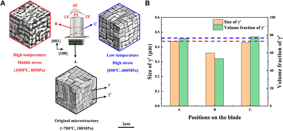
FIGURE 1. (A) SEM morphologies of the microstructure at three representative observation points on the blade, (B) area fractions and sizes of γ′ precipitates at different points.
Figure 1 illustrates the morphologies of the γ′ precipitates and the statistics of the characteristic parameters at the typical points. In Figure 1A, the morphologies of γ′ precipitates at different positions are presented. It can be found that γ′ precipitates at point A maintains with almost perfect cubic structure. At point B, γ′ precipitates have obviously rafted. When observing along the direction of <100> (i.e. direction vertical to centrifugal force), γ′ precipitates are obviously interconnected and evolves into a strip or plate in some positions with the rafting direction is perpendicular to the <001> direction. There are also some regions where γ′ precipitates are not completely connected to the surrounding precipitates, yet the cubic shape is also degraded to a spherical shape. In the direction of <001> (i.e. direction perpendicular to centrifugal force), the initial cubic γ′ precipitates have evolved into spherical shape and the adjacent spherical γ′ precipitates tend to connect with each other in both the <010> and <100> directions. In contrast, the precipitates at point C remain in a good cubic structure without rafting, and there is nearly no difference in the morphologies of γ′ precipitates with point A. Figure 1B shows the statistical results of the volume fraction and size of the precipitates at these three positions. Comparing the characteristic parameters of the precipitates at these three positions, it can be found that the parameters at points A and C are similar, while there are considerable gap between point B and the other two positions, where the size of the precipitates decreases by about 0.1 μm compared to position A (or C) and the volume fraction decreases by about 30%. This indicates that the temperature has a dominating role in the rafting of the γ′ precipitates.
Although the morphology of the γ′ precipitates can reflect the degradation of the material to some extent, defects such as dislocations and stacking faults are critical factors affecting the performance of the material. Dislocations contribute significantly in determining the creep behaviour of the material as well as effect on the rafting morphology of the γ′ precipitates by influencing elements diffusion (Ding et al., 2018; Qi et al., 2019). Creep is generally considered to have three stages, including the primary stage, the steady-state stage and accelerated stage, and all these three stages of creep correspond to distinct features of dislocation behavior (Reed, 2006). In the early stage of creep, γ′ precipitates start to raft while dislocations move only in the γ matrix channels, and the interface between the two phases hinders the dislocations movement resulting dislocations accumulate at the interfaces to form networks. In the steady-state creep stage, dislocations form a regular dislocation network at the interface of the two phases, which will further hinder dislocations from cutting into the γ′ precipitates, and only a few dislocations can cut into the γ′ precipitates. In the accelerated creep stage, a large number of dislocations cut into the γ′ precipitates, resulting in a significant decrease in the strength of γ′ precipitates, and the dislocations gather and entangle to form micropores, leading to the destruction of the material. Another point to emphasize is that external stress, temperature as well as material properties are inter-related, all these factors will have an impact on the initiation slip system and reaction types of the dislocations. Given the complex service environment of the blade, the dislocation behavior at different positions on the blade will be different and can reflect the external environment of the position to a certain extent. However, in most of the work related to turbine blades, the characterization of defects, such as dislocations and stacking faults, is often neglected or limited. For example, in Zhang (Zhang et al., 2020) and Gu et al.'s (Gu et al., 2021) work, which employed the similar turbine blades as our work, the microstructure of the blade was only characterized at the micron scale using SEM methods, which would limit the insight into microstructure degradation of service-exposed turbine blades.
Figure 2 shows TEM morphology of the precipitates and dislocations at point A with the position given in Figure 2A. Figure 2B shows a TEM image of a low magnification. It can be found that the γ′ precipitates maintain a good cubic structure, and at some positions can observe triangular precipitates (as indicated by the red arrows), which is probably due to the destruction of the complete cubic γ′ precipitates during the process of preparation of the sample and the γ′ cube is sheared along the slope leaving only a corner, so that only a triangle can be seen when observed under the TEM. Figure 2C shows the morphology of the sample observed at high magnification, revealing the presence of many short mismatch dislocations in the matrix phase (as shown by the blue arrows), which are mainly caused by the mismatch between the lattices of the two phases. Similar to that of the SEM, the γ′ precipitates at point A of the blade is not degraded, and only the mismatch dislocations formed during the heat treatment process exist, indicating that the mortise is essentially damage-free during service and satisfies the demand as a reference. In addition, the distribution of elements in DZ125 alloy is shown in Figure 2D, with Ni, Al, Ti, Hf, Ta, and W mainly enriched in the γ′ precipitates, while Cr, Co, and Mo are mainly enriched in the γ matrix.
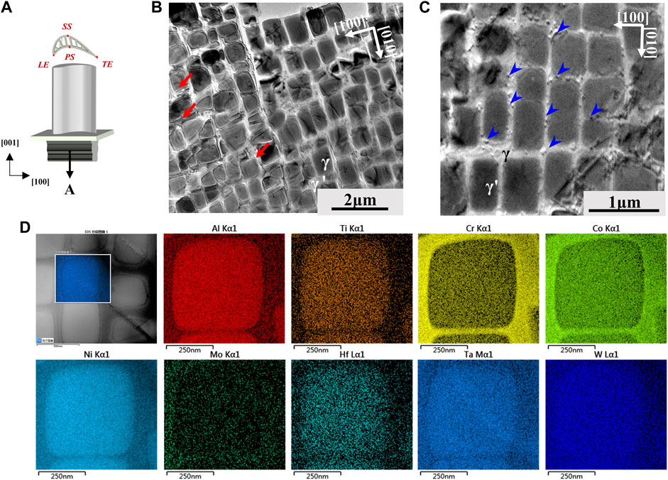
FIGURE 2. (A) The position of point A on the blade, (B–C) morphology of γ′ precipitates and dislocations at point A, (D) elemental distribution maps of the γ and γ'.
Point B on the blade is in a high temperature and low stress during service, and obvious rafting has occurred at point B according to the SEM image. To further analyze the dislocation behavior on the blade, it is necessary to investigate the microstructure at the nanoscale. STEM morphologies of dislocations at point B are given in Figure 3 with Figure 3A shows the position of point B on the blade. It can be seen in Figure 3B that the γ′ precipitates at point B have a distinct feature of rafting with the rafting direction perpendicular to the direction of centrifugal force (the direction of centrifugal force has been marked with black arrows in Figure 3B), and the original cubic structure has become ellipsoidal and connected, which is consistent with that observed in the SEM. It can be further noticed (as shown in Figure 3C) that no dislocations cut into the γ′ precipitates while there are only few dislocations in the γ matrix. Instead of a perfect phase-interface, the interface of the γ′ precipitates is extruded with some grooves by dislocations, which is shown as a short white line in the figure (as indicated by the orange arrow in Figure 3C). This may be due to the stress field caused by dislocations that affect the diffusion process of the elements (Mehrer, 1996; Ardell and Prikhodko, 2003), thereby pegging the migration of the two-phases interface and forming a groove structure at the interface. Similar phenomena are found in Figures 3D,E, both marked with orange arrows. Figures 3D,E gives the morphologies of dislocations at point B when observed along the [001] direction (i.e., parallel to the centrifugal force). As shown in Figure 3D, the surfaces of the γ′ precipitates are covered with a number of slip dislocations, which are only present on the surface of the γ′ precipitates rather than extending into the γ-matrix channel. It is indicated that the dislocations observed in Figure 3C are all located near the phase interface near the matrix phase. The dislocations in the area selected by the orange box in Figure 3D (Q1 and Q2) can be found to be interdigitated and have a tendency to form a dislocation network, while the other dislocations are chaotic, probably due to the complex stress state during service or the low level of heavy elements in the DZ125 alloy (it is usually considered that the more heavy elements, such as element Re and Ru, the more regular the dislocation network formed (Jin et al., 2010; Tan et al., 2013)). Moreover, it can be noticed in Figure 3D that some of the dislocations show an abrupt turn (indicated by the purple arrow), which might be due to the cross-slip shift and dislocation reaction of the
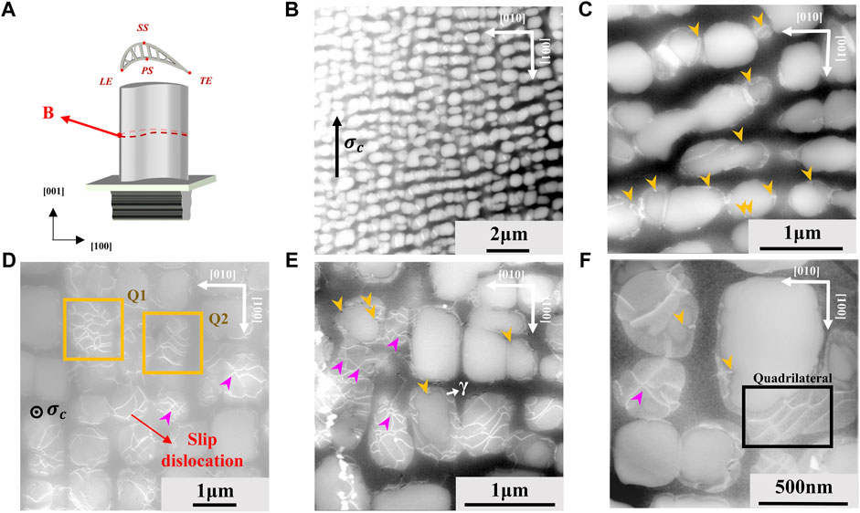
FIGURE 3. Microstructures at point B (A) the position of point B on the blade, (B) morphologies of rafted γ′ precipitates and (C) dislocations observed at <100> direction, (D–F) morphologies of γ′ precipitates and behavior of dislocations observed at <001> direction.
Despite the results shown in the SEM images that the volume fractions and sizes of the γ′ precipitates at points A and C are almost the same, a certain degree of damage at point C under high stress and low temperature can be predicted and the damage can be demonstrated by defects such as dislocations and stacking faults. Figure 4 gives the SEM morphologies of the defects at point C of the blade, all of which are observed in the [100] direction. The SEM image of low magnification at point C is shown in Figure 4B, and several traces of γ′ precipitates cut by dislocations can be seen (as indicated by the yellow arrows in Figure 4B), with most of them at an angle of 45° to the
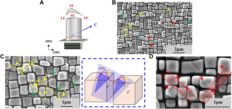
FIGURE 4. SEM morphologies of defects at point C of the blade: (A) the position of point C on the blade, (B) various defects on the surface of the γ′ precipitates at point C, (C) dislocations cut into the γ′ precipitates and a schematic diagram of dislocation behavior, (D) other feature on the surface of the γ′ precipitates.
The morphologies of dislocations at point C of the blade are given in Figure 5. Some typical types of dislocations are given in Figures 5A–D. Among them, the short dislocations indicated by yellow arrows in Figure 5A are mismatch dislocations, which are caused by lattice mismatch stress and have existed in the original heat treatment state of the material, and can also be observed at point A. The irregular dislocations line drawn with yellow dashed lines are slip dislocations, which are the main type of dislocations to form a dislocation network. Both of these dislocations are
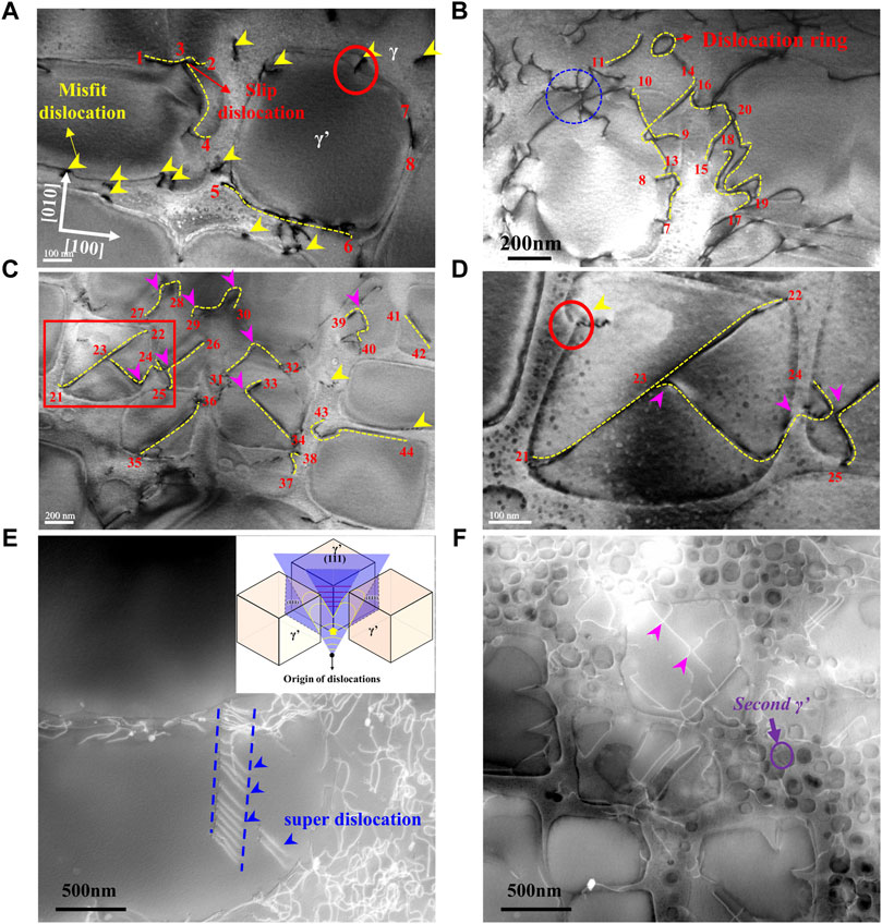
FIGURE 5. Dislocation morphologies at point C of the blade (A–D) TEM morphologies, (E–F) STEM morphologies.
Besides various types of dislocations at point C of the blade, there are also extensive stacking faults, which exist mainly at high stress with low temperature. Stacking faults are typically formed by two
The morphologies of the stacking faults at point C of the blade is given in Figure 6. In Figure 6A, the stacking faults are captured at a low magnification, and it can be observed that there are at least four stacking faults traversing several γ′ precipitates in this region, and these stacking faults are intersecting with each other. In Figure 6B is a magnified view of the stacking faults, it can be found that the stacking faults are a set of light and dark parallel lines observed from the <010> direction. Figure 6C shows the stacking fault in a single γ′ precipitate. The position which is marked by the red box indicates that the end of the stacking faults drags the interface of the two-phase, and the other end also has a similar effect but not obvious. The effect of stacking faults on the migration of the interface is essentially the effect of stacking faults on diffusion. To understanding the interaction between stacking faults and elements better, Figures 6D–F gives the atomic level STEM images at both ends of the stacking fault. Since STEM image is a mass-thickness contrast image, the larger the atomic number is, the brighter the atomic image is. It is evident from the Figure 6E and Figure 6F that there is a large number of heavy elements enriched in the stacking fault, which is also observed similarly in the work by Wu et al. (Wu et al., 2020), and the enrichment of elements may lead to a change in the chemical potential near the stacking faults, resulting in the effects of the stacking faults on the diffusion near the interface of the two phases. The atomic images at the two-phase interface are provided in Figure 6G, and it can be seen that there is no significant enrichment of heavy elements in either the γ′ precipitates or the γ matrix, which is only present near the stacking faults. Moreover, the enrichment of heavy elements near the stacking faults can also explain the traces left by the stacking faults observed in Figure 4D, where the elements in the stacking faults differ from the surrounding precipitates, leading to different degrees of etching and thus to the morphology of the stacking faults observed under SEM.
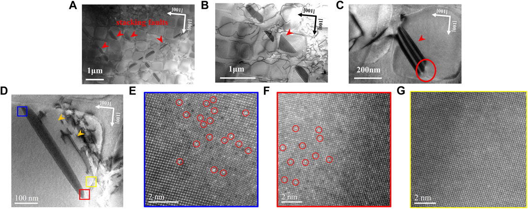
FIGURE 6. (A–D) Stacking fault morphologies at point C of the blade, (E–F) STEM images of the stacking fault at the atomic level, (G) STEM images of γ′ precipitate at the atomic level.
Although there is almost no obvious rafting or degradation for γ′ precipitates at point C of the blade, a large number of defects exist. In addition to the existence of numerous mismatch dislocations and slip dislocations, no dislocation network is formed. Moreover, secondary γ′ precipitates, super dislocations row and stacking faults cutting into the precipitates are observed in many areas, among which secondary γ′ precipitates exist at high temperature,
Turbine blades fabricated from directionally solidified superalloy DZ125 experienced complex service environment during service. With a view to understanding the degradation behavior of the microstructure on the blade, three typical observation points were selected, including point A as a reference, point B with high temperature and point C with high stress. By comparing microstructures of these three points at microscale and nanoscale, it can be revealed that the microstructure degradation of the blade after the service has the following characteristics.
1. The morphologies of microstructure on the turbine blade at different positions have great differences, which are attributed to the variation of service environment, and it indicates that the most severely damaged parts are required to be focused on when considering the remaining life of the blade.
2. At point B of the blade exposed to high temperature, the γ′ precipitates were rafted significantly, and the dislocations were mainly concentrated at the interface of the two phases without forming a regular dislocation network. Furthermore, the dislocation behavior indicated that this position was still in the first stage of creep.
3. At point C of the blade subjected to high stress, γ′ precipitates, with volume fraction and size similar to the original microstructure, have no significant degradation. However, there are a large number of defects, such as dislocations and stacking faults, etc. These defects exert a significant influence on the migration of the two-phase interface, which is probably due to the high dislocation driving force at point C resulting from the high stress. In addition, secondary γ′ occurring only at high temperature were observed at point C.
4. The number of various types of defects at point C of the blade indicates that the blade experienced a complex service history, so it is debatable whether the mechanical properties of the material tested under constant temperature and stress conditions can meet the remaining life assessment of the blade.
The original contributions presented in the study are included in the article/supplementary material, further inquiries can be directed to the corresponding author.
YX and JZ performed the experiments and analyzed the data. HW and JW designed the experiments and supervised the project. YX wrote the paper. HW revised the paper.
The authors acknowledge the support of Basic Science Center Program for Multiphase Evolution in Hyper-gravity of the National Natural Science Foundation of China (grant number 51988101); and the National Natural Science Foundation of China (grant number 52173302).
The authors declare that the research was conducted in the absence of any commercial or financial relationships that could be construed as a potential conflict of interest.
All claims expressed in this article are solely those of the authors and do not necessarily represent those of their affiliated organizations, or those of the publisher, the editors and the reviewers. Any product that may be evaluated in this article, or claim that may be made by its manufacturer, is not guaranteed or endorsed by the publisher.
Agudo Jácome, L., Nörtershäuser, P., Somsen, C., Dlouhý, A., and Eggeler, G. (2014). On the nature of γ' phase cutting and its effect on high temperature and low stress creep anisotropy of Ni-base single crystal superalloys. Acta Mater. 69, 246–264. doi:10.1016/j.actamat.2014.01.021
Aurrecoechea, J. M., Brentnall, W. D., and Gast, J. R. (1991). Service temperature estimation of turbine-blades based on microstructural observations. J. Eng. Gas. Turbine. Power 113, 251–260. doi:10.1115/1.2906556
Ardell, A. J., and Prikhodko, S. V. (2003). Coarsening of γ' in Ni–Al alloys aged under uniaxial compression: II. Diffusion under stress and retardation of coarsening kinetics. Acta Mater. 51, 5013–5019. doi:10.1016/s1359-6454(03)00327-6
Avila-Davila, E. O., Lopez-Hirata, V. M., Saucedo-Muñoz, M. L., Palacios-Pineda, L. M., Ramirez-Vargas, I., Cueto-Rodriguez, M. M., et al. (2018). Study of mechanical degradation and microstructural characterization in a Ni-based superalloy component of a gas turbine. Mater. Sci. Forum 941, 1248–1253. doi:10.4028/www.scientific.net/msf.941.1248
Chen, Y. D., Zheng, Y. R., Xiao, C. B., and Feng, Q. “Evaluation of temperature and stress in first stage high pressure turbine blades of a directionally-solidified superalloy DZ125 after service in aeroengines,” in Superalloys 2016: Proceedings of the 13th International Symposium on Superalloys, Hoboken, NJ, USA, 2016. Editors M. Hardy, E. Huron, U. Glatzel, B. Griffin, B. Lewis, C. Raeet al. (John Wiley & Sons), 701–710.
Chen, Y., Zheng, Y., and Feng, Q. (2016). Evaluating service temperature field of high pressure turbine blades made of directionally solidified Dz125 superalloy based on micro-structural evolution. Acta Metall. Sin. 52, 1545–1556. doi:10.11900/0412.1961.2016.00170
Cumpsty, N. A. (1997). Jet propulsion: A simple guide to the aerodynamic and thermodynamic design and performance of jet engines. Cambridge, United Kingdom: University Press.
Ding, Q., Li, S., Chen, L., Han, X., Zhang, Z., Yu, Q., et al. (2018). Re segregation at interfacial dislocation network in a nickel-based superalloy. Acta Mater. 154, 137–146. doi:10.1016/j.actamat.2018.05.025
Dubiel, B., and Czyrska-Filemonowicz, A. (2012). TEM analyses of microstructure evolution in ex-service single crystal CMSX-4 gas turbine blade. Solid State Phenom. 186, 139–142. doi:10.4028/www.scientific.net/ssp.186.139
Fu, C., Chen, Y., He, S., Antonov, S., Li, L., Zheng, W., et al. (2019). ICME framework for damage assessment and remaining creep life prediction of in-service turbine blades manufactured with Ni-based superalloys. Integr. Mat. Manuf. Innov. 8, 509–520. doi:10.1007/s40192-019-00161-4
Fu, C., Chen, Y., Li, L., Antonov, S., and Feng, Q. (2020). Evaluation of service conditions of high pressure turbine blades made of DS Ni-base superalloy by artificial neural networks. Mater. Today Commun. 22, 100838. doi:10.1016/j.mtcomm.2019.100838
Gad-Briggs, A., Pilidis, N., and Nikolaidis, T. (2017). A review of the turbine cooling fraction for very high turbine entry temperature helium gas turbine cycles for generation IV reactor power plants. J. Nucl. Eng. Radiat. Sci. 3, 1–10. doi:10.1115/1.4035332
Gan, W., Gao, H., Zhao, Y., Wen, Z., Lu, G., Jiang, B., et al. (2020). Influence of microstructure degradation induced by pretreatment on the creep behavior in Ni-based single-crystal superalloy with different orientations. J. Mat. Res. 35, 610–622. doi:10.1557/jmr.2020.35
Gu, S., Gao, H., Pei, H., Zhang, C., Wen, Z., Li, Z., et al. (2021). Degradation of microstructural and mechanical properties with serviced turbine blades. Mater. Charact. 182, 111582. doi:10.1016/j.matchar.2021.111582
He, J., Cao, L., Makineni, S. K., Gault, B., and Eggeler, G. (2021). Effect of interface dislocations on mass flow during high temperature and low stress creep of single crystal Ni-base superalloys. Scr. Mater. 191, 23–28. doi:10.1016/j.scriptamat.2020.09.016
Holländer, D., Kulawinski, D., Weidner, A., Thiele, M., Biermann, H., and Gampe, U. (2016). Small-scale specimen testing for fatigue life assessment of service-exposed industrial gas turbine blades. Int. J. Fatigue 92, 262–271. doi:10.1016/j.ijfatigue.2016.07.014
Huang, W., Li, S., Yang, X., Shi, D., and Qi, H. (2018). Experimental investigation and modelling of microstructure degradation in a DS Ni-based superalloy using a quantitative cross-correlation analysis method. J. Alloys Compd. 762, 488–499. doi:10.1016/j.jallcom.2018.05.131
Huang, W., Yang, X., and Li, S. (2019). Evaluation of service-induced microstructural damage for directionally solidified turbine blade of aircraft engine. Rare Met. 38, 157–164. doi:10.1007/s12598-018-1016-z
Jin, T., Wang, W. Z., Sun, X. F., and Hu, Z. Q. (2010). Role of rhenium in single crystal Ni-based superalloys. Mater. Sci. Forum 638, 2257–2262. doi:10.4028/www.scientific.net/msf.638-642.2257
Karlsson, S., Persson, C., and Persson, P. (1995). Metallographic approach to hirbine blade life time prediction. Mater. Manuf. Process. 10, 939–953. doi:10.1080/10426919508935081
Link, T., Epishin, A., Nawrath, N., Michel, C., and Nazmy, M. (2011). Dislocation structures in the gamma prime-phase of CMSX-4 and TMS75 after degradation under service conditions. Adv. Mat. Res. 278, 25–30. doi:10.4028/www.scientific.net/amr.278.25
Mehrer, H. (1996). The effect of pressure on diffusion. Defect Diffusion Forum 129-130, 57–76. doi:10.4028/www.scientific.net/ddf.129-130.57
Miura, N., Nakata, K., Miyazaki, M., Hayashi, Y., and Kondo, Y. (2010). Morphology of γ' precipitates in second stage high pressure turbine blade of single crystal nickel-based superalloy after serviced. Mater. Sci. Forum 638-642, 2291–2296. doi:10.4028/www.scientific.net/msf.638-642.2291
Persson, C., and Persson, P. O. (1993). Evaluation of service-induced damage and restoration of cast turbine blades. J. Mat. Eng. Perform. 2, 565–569. doi:10.1007/bf02661742
Qi, D., Wang, L., Zhao, P., Qi, L., He, S., Qi, Y., et al. (2019). Facilitating effect of interfacial grooves on the rafting of nickel-based single crystal superalloy at high temperature. Scr. Mater. 167, 71–75. doi:10.1016/j.scriptamat.2019.04.001
Rae, C. M. F., and Reed, R. C. (2007). Primary creep in single crystal superalloys: Origins, mechanisms and effects. Acta Mater. 55, 1067–1081. doi:10.1016/j.actamat.2006.09.026
Rae, C. M. F., Rist, M. A., Cox, D. C., Reed, R. C., and Matan, N. (2000). On the primary creep of CMSX-4 superalloy single crystals. Metall. Mat. Trans. A 31, 2219–2228. doi:10.1007/s11661-000-0139-6
Rae, C. M. F., and Zhang, L. (2009). Primary creep in single crystal superalloys: Some comments on effects of composition and microstructure. Mater. Sci. Technol. 25, 228–235. doi:10.1179/174328408x369311
Reed, R. (2006). The superalloys fundamentals and applications. Cambridge, United Kingdom: Cambridge University Press.
Ren, P., Huang, W., Yang, X., Huang, J., Shi, Y., and Fan, Y. (2021). A modified constitutive model considering microstructure degradation of Ni-based superalloys and its application to microstructural damage calculation. J. Alloys Compd. 882, 160605. doi:10.1016/j.jallcom.2021.160605
Schwalbe, C. W. M. (2019). Analysis and modelling of the dislocation response during non-isothermal creep in Ni-SX superalloys. Cambridge, United Kingdom: University of Cambridge.
Singh, K. (2014). Advanced materials for land based gas turbines. Trans. Indian Inst. Met. 67, 601–615. doi:10.1007/s12666-014-0398-3
Tan, X. P., Liu, J. L., Jin, T., Hu, Z. Q., Hong, H. U., Choi, B. G., et al. (2013). Effect of Ru additions on very high temperature creep properties of a single crystal Ni-based superalloy. Mater. Sci. Eng. A 580, 21–35. doi:10.1016/j.msea.2013.05.028
Tong, J., Ding, X., Wang, M., Yagi, K., Zheng, Y., and Feng, Q. (2016). Assessment of service induced degradation of microstructure and properties in turbine blades made of GH4037 alloy. J. Alloys Compd. 657, 777–786. doi:10.1016/j.jallcom.2015.10.071
Tsukada, Y., Koyama, T., Kubota, F., Murata, Y., and Kondo, Y. (2017). Phase-field simulation of rafting kinetics in a nickel-based single crystal superalloy. Intermetallics 85, 187–196. doi:10.1016/j.intermet.2017.02.017
Van Sluytman, J. S., and Pollock, T. M. (2012). Optimal precipitate shapes in nickel-base γ–γ′ alloys. Acta Mater. 60, 1771–1783. doi:10.1016/j.actamat.2011.12.008
Wang, C., Ali, M. A., Gao, S., Goerler, J. V., and Steinbach, I. (2019). Combined phase-field crystal plasticity simulation of P- and N-type rafting in Co-based superalloys. Acta Mater. 175, 21–34. doi:10.1016/j.actamat.2019.05.063
Wang, X. G., Liu, J. L., Jin, T., Sun, X. F., Zhou, Y. Z., Hu, Z. Q., et al. (2015). Creep deformation related to dislocations cutting the γ' phase of a Ni-base single crystal superalloy. Mater. Sci. Eng. A 626, 406–414. doi:10.1016/j.msea.2014.12.060
Wen, Z., Hou, N., Wang, B., and Yue, Z. (2010). Crystallographic life model for single crystal turbine blade and validation by the miniature specimens cut from the turbine blades. Multidiscip. Model. Mater. Struct. 6, 508–529. doi:10.1108/15736101011095163
Wu, X., Makineni, S. K., Liebscher, C. H., Dehm, G., Mianroodi, J. R., Shanthraj, P., et al. (2020). Publisher Correction: Unveiling the Re effect in Ni-based single crystal superalloys. Nat. Commun. 11, 1076. doi:10.1038/s41467-020-14820-0
Yue, Q., Liu, L., Yang, W., He, C., Sun, D., Huang, T., et al. (2019). Stress dependence of the creep behaviors and mechanisms of a third-generation Ni-based single crystal superalloy. J. Mat. Sci. Technol. 35, 752–763. doi:10.1016/j.jmst.2018.11.015
Keywords: turbine blade, microstructure, degradation, stacking fault, dislocation, superalloy
Citation: Xie Y, Zhao J, Wang J and Wei H (2022) Microstructure degradation of service-exposed turbine blades made of directionally solidified DZ125 superalloy. Front. Mater. 9:973119. doi: 10.3389/fmats.2022.973119
Received: 19 June 2022; Accepted: 11 August 2022;
Published: 07 September 2022.
Edited by:
Xiangming Zhou, Brunel University London, United KingdomReviewed by:
Xuewei Fang, Xi'an Jiaotong University, ChinaCopyright © 2022 Xie, Zhao, Wang and Wei. This is an open-access article distributed under the terms of the Creative Commons Attribution License (CC BY). The use, distribution or reproduction in other forums is permitted, provided the original author(s) and the copyright owner(s) are credited and that the original publication in this journal is cited, in accordance with accepted academic practice. No use, distribution or reproduction is permitted which does not comply with these terms.
*Correspondence: Hua Wei, aHVhd2VpQHpqdS5lZHUuY24=
Disclaimer: All claims expressed in this article are solely those of the authors and do not necessarily represent those of their affiliated organizations, or those of the publisher, the editors and the reviewers. Any product that may be evaluated in this article or claim that may be made by its manufacturer is not guaranteed or endorsed by the publisher.
Research integrity at Frontiers
Learn more about the work of our research integrity team to safeguard the quality of each article we publish.