 Shixuan Yi1Jianmei Liu2*
- 1Structural Engineer, Guangzhou Metro Design & Research Institute Co., Ltd., Guangzhou, China
- 2Director of Structure Institute, Guangzhou Metro Design & Research Institute Co., Ltd., Guangzhou, China
The construction of railway and highway embankments has a significant influence on the behavior of existing pile foundations, especially in the situation of high embankments and extensively soft soils, which are commonly encountered in coastal areas. A high embankment might produce large lateral movement and bending moment to the existing adjacent piles, which would cause the failure of the pile if the surcharge loading is not properly considered. A field test was designed and performed to investigate the effect of lateral surcharge loading on the existing adjacent pile in extensively soft soils. A 4 m high embankment was constructed in five lifts and was close to the existing adjacent steel pipe pile with a length of 35 m. The deformation of the pile and the soft soils, the excess pore water pressure, and lateral earth pressures were measured during the surcharge loading test. The test results showed that the lateral displacement of the steel pipe pile at the ground surface exceeded 229.9 mm and could not maintain constant due to the surcharge loading. The lateral displacement decreased along with the pile depth and was relatively small when the pile depth exceeded 10 m. Large lateral displacements were observed in the soft soils at different locations. The surcharge loading zone showed obvious downward displacements, while the soft soils close to the loading zone showed upward displacements. The excess pore water pressure changed regularly with the construction of the embankment, and its maximum value reached 53.6 kPa. The lateral earth pressures that acted on the pile continuously increased with the increase in the embankment height, which caused large deformation of the pile.
Introduction
Lateral soil movement caused by self-weight or external factors known as the passive pile differs from lateral loads applied at the pile head, which is an active pile for the lateral bearing modes of pile foundations. In many cases, the design and failure of piles are governed by lateral performance. Examples of passive piles include existing piles near piling (Poulos, 1994), piles for stabilizing slopes (Ito et al., 1982; Bai et al., 2021), piles adjacent to the tunneling and excavation project (Poulos and Chen, 1997; Madhumathi and Ilamparuthi, 2018; Ong, 2018; Madhumathi and Abisha, 2020; Li et al., 2021), and piles close to surcharge (Bransby and Springman, 1996; Bai et al., 2022). The interaction between piles and moving soil is very complicated. For the bridge pile adjacent to an embankment to be built, the pile may face the following challenges: 1) the external vertical loads (for example, superstructure objects and vehicles) applied to the pile head, 2) external lateral loads (for example, wind load and earthquake load) applied to the pile head (that is, active loading), and 3) the additional soil pressures acting on the pile shaft due to the surcharge (that is, passive loading).
Several studies have been conducted to evaluate the lateral response of the pile adjacent to surcharge loading, such as laboratory tests (Al-abboodi et al., 2020; Karkush et al., 2020; Karkush and Jaffar, 2020; Toma Sabbagh et al., 2020), finite element method (Xu and Poulos, 2001; Karim, 2013; Al-abboodi and Sabbagh, 2019), and theoretical approach (Springman, 1989; Zhang et al., 2020a; Bellezza, 2020; Zhang et al., 2020b). The laboratory tests, numerical method, and theoretical analysis (Chen and Poulos, 1997; Ellis and Springman, 2001; Abo-Youssef et al., 2021; Ramalakshmi, 2021) proved that the effect of movement soil would lead to large deformation or even failure of the pile. However, numerical models, laboratory tests, and theoretical derivation wherein unidentified in actual conditions (properties of soil and shape of stratum) might not entirely reflect the field’s authenticity and directly calibrate the results. Field monitor in actual cases is an effective and reliable method to analyze the soil-pile interaction caused by the surcharge. Field data can be used to investigate the interaction effect of soil–piles–surcharge and support the design procedure.
The mechanical behavior of passively loaded piles with nearby inclined bedrock was tested in the laboratory, and the result concluded that under the low load condition, the pile far from the load boundary was mainly in a tensile state (Xie et al., 2018). Heyman (1965) adopted the resistance strain gauges to record the pile’s displacement and stress and roughly used the pile’s displacement to estimate the pile’s bending moment. The error between the test and the calculated bending moment was 20%. Nicu et al. (1971) measured the lateral displacement of six piles and the abutment on 13.5 m thick hard clay and found that the undrained shear strength of soft soil equaled three times the limit value of the abutment. Karkush and Kareem (2021) studied the behavior of axially loaded piles in contaminated clay soil adjacent to the construction of embankments, finding that the increase of embankment settlement led to the increase of lateral displacement of the soil surface. Poulos (1972) listed different engineering cases and showed that the measured settlement is consistent with the settlement predicted by FEM. The predicted displacement was much more sensitive than the vertical displacement, and the predicted value at the foot of the subgrade slope was even more than 1.5 times the measured value. Tavenas et al. (1979) analyzed the lateral displacement of soft soil during the construction and consolidation of 21 embankments. The results showed that the magnitude of the lateral displacement was very difficult to predict when the construction was completed. It depended mainly on the drainage of the foundation, the geometric characteristics, the mechanical properties, the loading rate, and the consolidation rate.
The field test was important for the analysis of passively loaded piles. The construction of railway and highway embankments has a significant influence on the behavior of existing pile foundations, especially in the situation of high embankments and extensively soft soils, which are commonly encountered in coastal areas. The mechanism of soil–pile interaction due to the construction of the embankment in extensively soft soils was not fully understood and needed further investigation. The high embankment might produce large lateral movement and bending moment to the existing adjacent piles, which would cause the failure of the pile if the surcharge loading is not properly considered. A field test was designed and performed to investigate the effect of lateral surcharge loading on the existing adjacent pile in extensively soft soils. The deformation of the pile and the soft soils, the excess pore water pressure, and lateral earth pressures were measured during the surcharge loading test and presented as follows.
Project overview
The field test was performed in Guangdong Province, China. The region represented the geological characteristic of the Pearl River Delta alluvial plain in the coastal area of South China. This region is typically composed of farmland, ponds, and rivers. Pile foundations with elevated caps for the bridge are commonly used to solve the geotechnical problems in this region. Table 1 shows the geological profiles based on borehole logs. The soil is mainly composed of fill, marine deposits, alluvium, and completely decomposed granite. The soft soil with a large thickness was distributed in the whole field for this project. Table 2 shows the physical properties of the soil based on experimental tests.
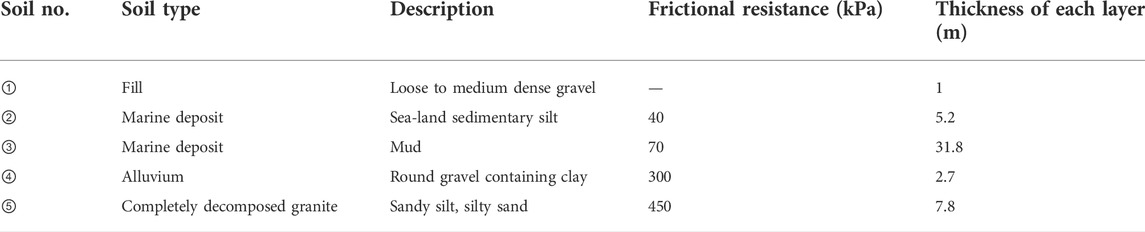
TABLE 1. Geological profiles.
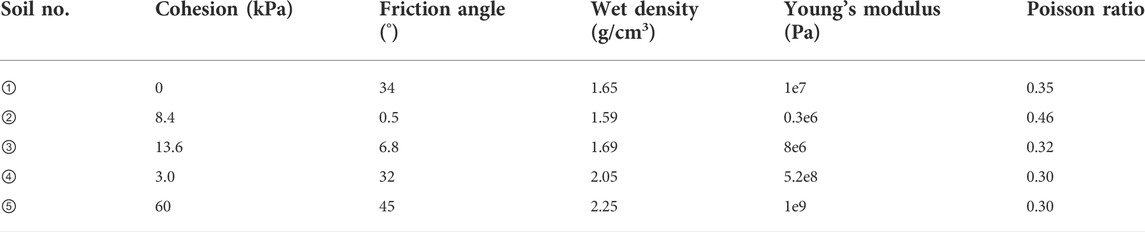
TABLE 2. Physical and mechanical properties of the soil.
Instrumentation and measurement
The test pile was a steel pipe pile with an outer diameter of 610 mm, a wall thickness of 10 mm, and a length of 35 m. The bottom of the pile was open for the convenience of piling construction. The bending stiffness of the steel pipe pile used in the field test was 1.611 × 10⁹ N/m2. Figure 1 shows the instrumentation layout of the field test. The area of the embankment fill was 24 m in length and 16 m in width. The slope gradient of the fill was 1:1.5. In order to investigate the response of pile foundations under lateral surcharge loading, a 4 m high embankment was constructed in five lifts (each lift was 0.8 m thick) close to an existing single pile. The deformation of the pile and the soft soils, the excess pore water pressure, and lateral earth pressures were measured during the surcharge loading test. The detail of the instrumentation and the test procedures were as follows.
1) The vibration piling method was used in the field test to ensure that the pile penetrated the extensively soft soil. The steel pipe pile was 35 m long, and the bottom of the pile floated in the mud soil.
2) Four inclinometer tubes (PVCs) were installed at different distances from the fill in the foundation soil (with a label of 1#, 2#, 3#, and 4#, respectively, from left to right, as shown in Figure 1, to measure the lateral movement of the soil. In addition, two inclinometer tubes (PVCs) were constructed along the outer surface of the steel pipe pile to measure the horizontal displacement of the pile (with labels of 5# and 6#, as shown in Figure 1). The length of each PVC tube was 30 m. The outer and inner diameters of the tube were 70 and 60 mm, respectively. After the installation of the inclinometer tubes, the initial readings were measured before the construction of the embankment fill.
3) A total of 15 earth pressure cells were installed at the surface of the steel pipe pile at different depths. The test surface of the earth pressure cells was kept flush with the outer surface of the pile in order to measure the lateral earth pressure accurately. The earth pressure cell was supported by a rigid bracket welded on the steel pipe. The earth pressure cell contained precise test elements and some necessary protection measures that were taken to reduce the vibration effect during the piling construction of the steel pipe pile. Figure 1 shows that ten Earth pressure cells were installed in the direction facing the embankment. Five earth pressure cells within a depth of 5 m were located with a vertical interval of 1 m. Other earth pressure cells were located with a vertical interval of 2 m. At the normal direction of the steel pipe pile, five earth pressure cells were installed in the vertical direction with an interval of 2 m.
4) The pore-water pressure transducers (PPTs) were buried in soft soil at four locations with a depth of 1.5 m from the ground surface. The PPT was put into the hole formed by drilling equipment, and the holes were filled with fine sand. The data acquisition system was connected and recorded the pore water pressures automatically. The initial reading was measured before the construction of the embankment fill.
5) The total station and level instrument were used to measure the horizontal displacement of the pile and the vertical deformation of the ground surface, respectively. The marks were set at the corresponding locations of the pile and the ground surface. Nine settlement observation plates with an area of 40 cm × 40 cm were placed at different locations. Three plates were placed at the top surface of the embankment. Three plates were placed on the embankment toe close to the pile. Three plates were placed on the embankment toe far away from the pile.
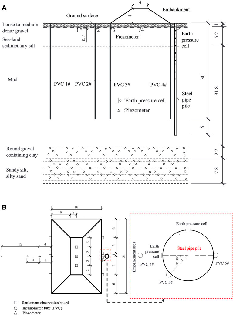
FIGURE 1. Instrumentation layout of the field test: (A) sectional view and (B) plan view (unit: m).
After the construction of the steel pipe pile and the instrumentation, the embankment fill was placed in five lifts. Each lift was compacted and had a thickness of 0.8 m. Figure 2 shows the construction consequence of the embankment fill. The embankment height was kept constant for three days, and the next lift was placed on the top of the embankment. The deformation of the pile and the soft soils, the excess pore water pressure, and lateral earth pressures were measured and recorded at different embankment heights. This procedure would be repeated until the embankment height reached 4 m.
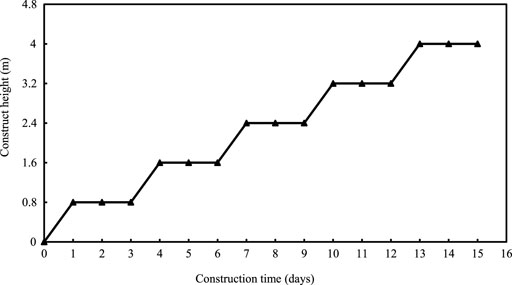
FIGURE 2. Construction consequence of the embankment fill.
Results and discussion
Horizontal displacement of the pile
Figure 3 shows the horizontal displacement of the pile at the ground surface obtained by the inclinometer (PVC 6#). The horizontal displacement of the pile increased with the increase of the embankment height. The horizontal displacement increased rapidly after the placement of a new lift. The displacement then remained relatively constant during the observation period of three days for the first three lifts. The pile was capable of withstanding the lateral surcharge loading. However, the horizontal displacement of the pile continued to increase with time and could not maintain constant when the embankment height reached 3.2 m. After the construction of five lifts, the horizontal displacement of the pile rapidly increased with time and showed an unstable state. The observed maximum horizontal displacements of the pile under each lift were 36.3, 67.0, 122.9, 176.9, and 229.9 mm, respectively.
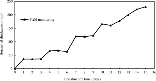
FIGURE 3. Horizontal displacement of the pile at the ground surface.
The horizontal displacement of the pile measured by the total station was compared with that measured by the inclinometer. Table 3 illustrates the increment of the horizontal displacement under each lift. It can be seen that the results measured by different methods were relatively close, and the maximum error was −17.4%, which was acceptable in the field investigation. The error of the horizontal displacement measurement was defined as follows.
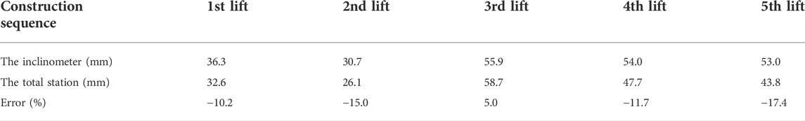
TABLE 3. Comparison of the increment of the horizontal displacement measured by different methods.
The embankment construction caused the stress redistribution and displacement of the pile and soil caused, which would make the pile–soil interaction more complicated if the lift was close to the pile. The embankment produced a vertical load on the ground surface and resulted in the displacement of the soil moving away from the surcharge area. The soil movement would apply additional pressure on the pile. The horizontal displacement of the pile depended on the lateral movement of the soil and was time-dependent, as shown in Figure 3. The movement of the soil was also time-dependent and would result in a continuous increase in pile displacement (Abo-Youssef et al., 2021). The observed results in this field investigation demonstrated that the pile close to the surcharge failed after the fourth lift (the construction time of the 11th day).
Pile bending
The inclinometer of the PVC 5# and 6# were used to investigate the horizontal displacement along the pile depth. Figure 4 shows that the horizontal displacement of the pile was significant with the increase of the load for both PVC 5# and 6#. The horizontal displacement of the pile decreased rapidly along the pile depth at each surcharge loading. The data measured by PVC 5# showed that the major displacement occurred within a depth of 10 m. The horizontal displacements of the pile at the ground surface measured by PVC 5# were 64.3, 117.6, 192.5, 236.7, and 273.0 mm, respectively, corresponding to each surcharge loading. The data measured by PVC 6# showed some difference compared with the data from PVC 5#. The horizontal displacement of the pile decreased rapidly with the increase of the depth in the shallow layer of about 7.5 m. The horizontal displacements of the pile at the ground surface measured by PVC 5# were 39.8, 67.0, 122.9, 166.2, and 220.1 mm, respectively, corresponding to each surcharge loading.
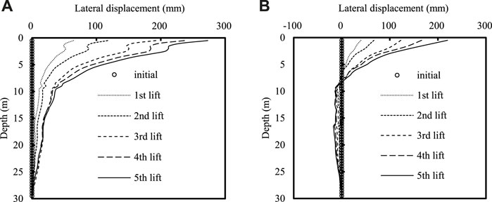
FIGURE 4. Horizontal displacement along the pile depth measured by (A) PVC 5# and (B) PVC 6#.
It is of note that the pile bending developed since the first surcharge loading. Figure 4 shows that PVC 6# occurred in a contraflexure, and the main positive displacement developed for the depth of 7.5 m. The PVC 5# did not occur in the contraflexure, and the main region of displacement exceeded 7.5 m to the deeper position. The aforementioned difference was caused by the different installation locations of the PVC. The PVC 5# was installed on the opposite side of the pile, which was different from the location of PVC 6# (as shown in Figure 1). The PVC 5# may develop additional bending and movement during each surcharge loading. The soil movement forced the pile to carry additional lateral earth pressure, which caused the unexpected lateral deformation of the PVC.
Lateral displacement of the soft soil
Figure 5 shows the horizontal displacement of the soil measured by PVC 1#, 2#, 3#, and 4# at different locations. The horizontal displacement of the soil was more significant with the increase of the load at the location of PVC 2#, 3#, and 4#. The horizontal displacement of the soil measured by PVC 2# decreased with the increase of the depth. The horizontal displacement of the soil measured by PVC 3# and PVC 4# increased with the increase of the depth for the shallow layers (the depth varied from 2 to 4 m) and then decreased with the increase of the depth. The horizontal displacement of the soil measured by PVC 1# changed slightly with the increase of the load. The displacement measured by PVC 1# and 4# showed negative values. The maximum value of the displacement measured by PVC 1# was −9.6 mm, which indicated that the effect of the surcharge loading was negligible for the soil far away from the center of the loading area (the distance was 24 m in this case). The horizontal displacements at the location of PVC 2# developed the maximum value at the ground surface and were 17.3, 25.1, 47.0, 69.2, and 93.7mm, respectively, for different surcharge loading stages. The maximum displacements of the soil measured by PVC 3# and 4# were 148.2 and 348.8mm, respectively.
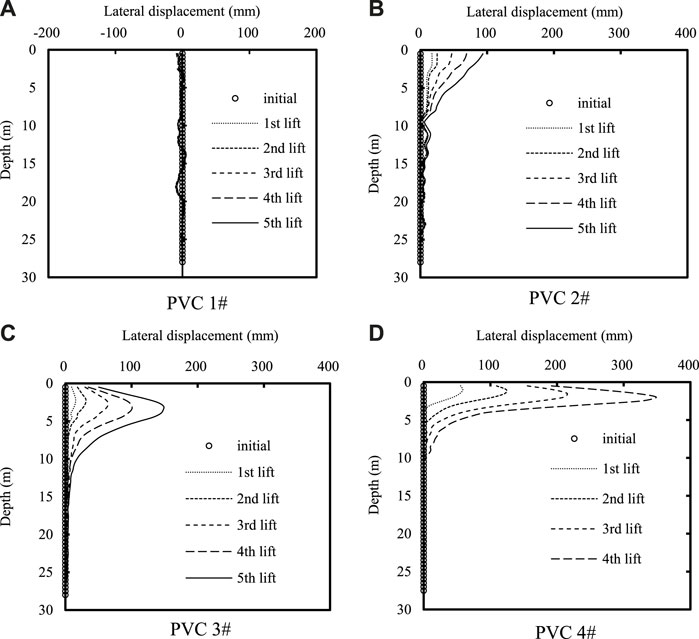
FIGURE 5. Horizontal displacement of the soil measured by (A) PVC 1#, (B) 2#, (C) 3#, and (D) 4# with depth under different surcharge loading stages.
Figure 5 shows that the lateral displacement of the soil at the edge of the surcharge loading area was larger than that for the soil far away from the surcharge and was smaller for the soil closer to the ground surface (the location of PVC 3# and 4#). The displacement increased with the decrease of the distance from the loading area in the sequence of PVC 1#, 2#, and 3#. The displacement measured by PVC 4# was larger than other locations measured by PVC 1#, 2#, and 3#. The pile provided more resistance to the earth pressure which was caused by soil movement and surcharge loading. The lateral thrust of the soil could not be neglected for the design of the passively loaded pile. The shape of the displacement profile in the PVC 3# was different from the profile of the PVC 2#, which indicated that the movement of soil diffused outward with the increase of the distance between the soil and the loading area.
Settlement of the embankment
The settlement of the embankment during construction was monitored by nine settlement observation plates placed at different locations. Figure 6 shows the location of settlement observation plates. Three plates were placed at the top surface of the embankment fill. Three plates were placed at the embankment toe close to the pile. Three plates were placed at the embankment toe far away from the pile. Figure 7 shows the settlement of the embankment versus construction time at different loading stages. The settlement at the center of the loading area (D-4, D-5, and D-6) increased with the increase of the embankment height. On the contrary, the soil on both sides of the surcharge area developed negative settlement (the soil heave) and the deformation changed with time irregularly. The average settlement of D-4, D-5, and D-6 was 0.2, 13.7, 22.5, 46.0, and 64.2 cm, respectively, for different surcharge loading stages. The maximum heave height for the side without steel pipe pile (D-7, D-8, and D-9) and with steel pipe pile (D-1, D-2, and D-3) were 29.4 and 77.2 cm, respectively, after the completion of the embankment construction. The vertical deformation of the embankment soil was significant compared with the lateral movement of the soil. The soil at the center of the loading area showed downward vertical deformation. The soil at the edge of the loading area showed upward vertical deformation. The maximum vertical deformation occurred at the edge with the steel pipe pile and was larger than the settlement at the center of the loading area. The existence of the steel pipe pile constrained the lateral movement of the soft soil; therefore, the soil close to the pile moved upward and resulted in larger heave deformation than the soil on the other side without the pile.
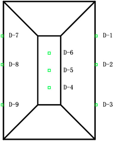
FIGURE 6. The location of settlement observation plates.
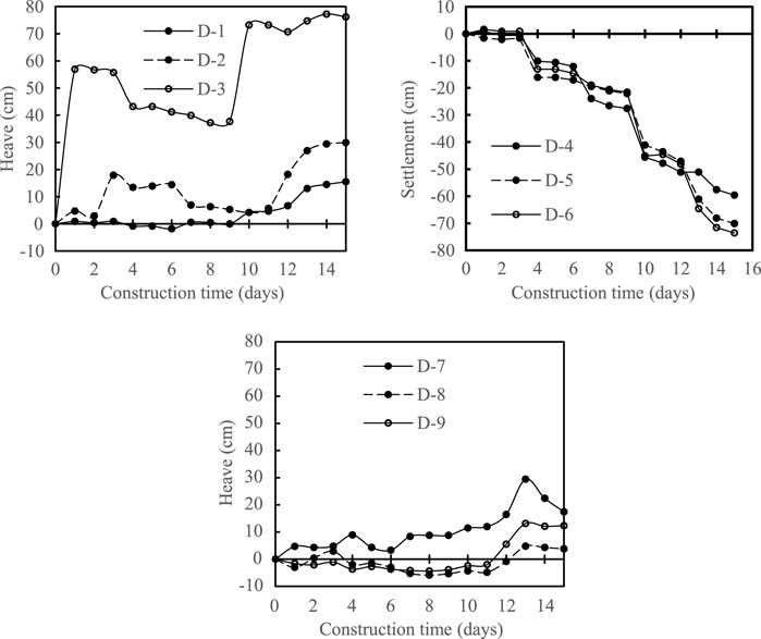
FIGURE 7. Settlement of the embankment versus construction time at different loading stages.
Excess pore-water pressure
The water table of the site was 1 m below the ground surface. The excess pore-water pressure (EPP) of the soil was measured by the pore-water pressure transducers (PPTs), which were buried in soft soil at four locations with a depth of 1.5 m from the ground surface. The location of PPTs was presented in Figure 1. Figure 8 shows the value of the EPP measured by PPTs varied with time. It can be seen from Figure 8 that the EPP increased rapidly after the placement of each lift and then gradually dissipated with time before the next lift. The PPT 4# was located in the center of the loading area and was significantly affected by the surcharge loading. Its maximum value of EPP reached 52 kPa for the placement of the second to the fourth lift. The dissipation of the EPP with the time was obvious for each placement of the lift. The rapid increase of the EPP indicated that the soft soil carried additional vertical stress due to the surcharge loading, which would result in the shear failure of the foundation soil if the surcharge loads was inappropriately high or the dissipation of the EPP was not well considered in the embankment construction.
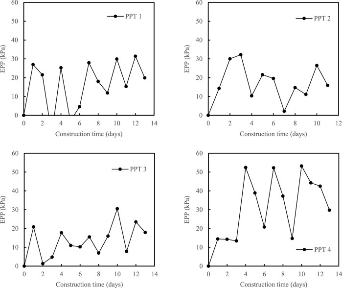
FIGURE 8. Excess pore-water pressure (EPP) of the soil versus the construction time.
Lateral earth pressure on the pile
The lateral earth pressure that acted on the pile was measured by the earth pressure cells installed in the steel pipe pile (as presented in Figure 1). Ten earth pressure cells directly facing the surcharge were labeled as A-1 to A-10 and located along the pile depth. Five earth pressure cells were labeled as B-1 to B-5 in the normal direction. Some earth pressure cells did not work properly during the test due to construction damages and complicated measurement environments. Figure 9 shows test results of the lateral earth pressure at different pile depths versus the construction time. A-2 was buried at a depth of 2 m. Its initial earth pressure (measured before the first lift) was 8 kPa and increased to 16 kPa after the placement of the first lift. A-2 was damaged, and there was no more reading. The depth of the B-1, B-2, and B-3 were 2, 4, and 6 m, respectively, in another direction. The initial earth pressure for the B-1, B-2, and B-3 were 32, 49, and 65 kPa, respectively. The earth pressure increased with the increase of the embankment thickness for the B-1, B-2, and B-3. The earth pressures of the B-1 were 29, 32, 32, 34, and 35 kPa, respectively, for the placement of each lift. The change of earth pressure at this location was small due to the increase of the surcharge load. The earth pressures of the B-2 were 54, 61, 66, 68, and 71 kPa, respectively, for the placement of each lift. The earth pressures of the B-3 were 68, 72, 83, 86, and 88 kPa, respectively, for the placement of each lift. The earth pressure of B-2 and B-3 changed obviously with the increase of the surcharge load. The earth pressures eventually increased up to 3, 22, and 23 kPa, respectively, for the B-1, B-2, and B-3 after the completion of the embankment construction. The increased lateral earth pressure put additional horizontal loads on the steel pipe pile, which caused a disadvantageous situation for the pile foundation.
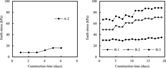
FIGURE 9. The lateral earth pressure at different pile depths versus the construction time.
Conclusion
In this research study, an embankment of 4.0 m in thickness was constructed in five lifts to investigate the performance of the steel pipe pile under lateral surcharge loading. The deformation of the pile and the soft soils, the excess pore-water pressure, and lateral earth pressures that acted at the pile were measured during the test. Based on the results obtained from the field test, the following conclusions were drawn:
1) The maximum horizontal displacement of the pile reached 229.9 mm due to the surcharge loading. The displacement increased rapidly and was unable to maintain for the fourth and fifth lifts. The lateral displacement decreased along with the pile depth. The displacement was relatively small when the pile depth exceeded 10 m.
2) The lateral displacement of the soft soil increased with the decrease of the distance from the loading area. The influence area of a 4 m high embankment surcharge in this field test was about 24 m from the surcharge center based on the consideration of the negligible lateral displacement of the soil.
3) The surcharge loading zone developed downward vertical displacement (settlement), while the soft soils at the edge of the loading zone developed upward vertical displacement (heave deformation). The maximum vertical deformation occurred at the edge with the steel pipe pile and was larger than the settlement at the center of the loading area.
4) The excess pore-water pressure changed regularly with the construction of each lift, and the maximum value reached 53.6 kPa. The lateral earth pressures that acted on the pile continuously increased with the increase of the embankment height, which caused large deformation of the pile.
Data availability statement
The original contributions presented in the study are included in the article/Supplementary Material; further inquiries can be directed to the corresponding author.
Author contributions
SY was the first author and was in charge of the field test and analysis. JL was the corresponding author and was in charge of the test plan and writing.
Conflict of interest
Authors SY and JL were employed by the Guangzhou Metro Design & Research Institute Co., Ltd.
Publisher’s note
All claims expressed in this article are solely those of the authors and do not necessarily represent those of their affiliated organizations, or those of the publisher, the editors, and the reviewers. Any product that may be evaluated in this article, or claim that may be made by its manufacturer, is not guaranteed or endorsed by the publisher.
References
Abo-Youssef, A., Morsy, M. S., ElAshaal, A., and ElMossallamy, Y. M. (2021). Numerical modelling of passive loaded pile group in multilayered soil. Innov. Infrastruct. Solut. (6), 101. doi:10.1007/s41062-021-00464-6
Al-abboodi, I., Sabbagh, T. T., and Al-salih, O. (2020). Response of passively loaded pile groups-an experimental study. Geomechanics Eng. 20, 333–343.
Al-abboodi, I., and Sabbagh, T. T. (2019). Numerical modelling of passively loaded pile groups. Geotech. Geol. Eng. (Dordr). 2747 (37), 2747–2761. doi:10.1007/s10706-018-00791-z
Bai, Bing, Nie, Qingke, Zhang, Yike, Wang, Xiaolong, and Hu, Wei (2021). Cotransport of heavy metals and SiO2 particles at different temperatures by seepage. J. Hydrology 597, 125771. doi:10.1016/j.jhydrol.2020.125771
Bai, Bing, Wang, Yan, Rao, Dengyu, and Fan, Bai (2022). The effective thermal conductivity of unsaturated porous media deduced by pore-scale SPH simulation. Front. Earth Sci. (Lausanne). 10. doi:10.3389/feart.2022.943853
Bai, Bing, Zhou, Rui, Cai, Guoqing, Hu, Wei, and Yang, Guangchang (2021). Coupled thermo-hydro-mechanical mechanism in view of the soil particle rearrangement of granular thermodynamics. Comput. Geotechnics 137 (8), 104272. doi:10.1016/j.compgeo.2021.104272
Bellezza, I. (2020). Closed-form expressions for a rigid passive pile in a two-layered soil. Géotechnique Lett. 242 (10), 242–249. doi:10.1680/jgele.19.00250
Bransby, M., and Springman, S. (1996). 3-D finite element modelling of pile groups adjacent to surcharge loads. Comput. Geotechnics 19, 301–324. doi:10.1016/0266-352x(95)00001-q
Chen, L., and Poulos, H. (1997). Piles subjected to lateral soil movements. J. Geotech. Geoenviron. Eng. (123), 802–811. doi:10.1061/(asce)1090-0241(1997)123:9(802)
Ellis, E., and Springman, S. (2001). Full-height piled bridge abutments constructed on soft clay. Geotechnique (51), 3–14. doi:10.1680/geot.2001.51.1.3
Heyman, L. (1965). Measurement of the influence of lateral earth pressure on pile foundations. Toronto: Soil Mech & Fdn Eng Conf Proc/Canada/.
Ito, T., Matsui, T., and Hong, W. P. (1982). Extended design method for multi-row stabilizing piles against landslide. Soils Found. (22), 1–13. doi:10.3208/sandf1972.22.1
Karim, M. R. (2013). Behaviour of piles subjected to passive subsoil movement due to embankment construction – a simplified 3D analysis. Comput. Geotechnics 1 (53), 1–8. doi:10.1016/j.compgeo.2013.04.004
Karkush, M. O., Aljorany, A. N., and Jaffar, G. S. (2020). Behavior of passive single pipe pile in sandy soil. IOP Conf. Ser. Mat. Sci. Eng. (737), 012106. doi:10.1088/1757-899x/737/1/012106
Karkush, M. O., and Jaffar, G. S. (2020). Simulation the behavior of passive rigid pile in sandy soil. J. Eng. Technol. Sci. 449 (52), 449–467. doi:10.5614/j.eng.technol.sci.2020.52.4.1
Karkush, M. O., and Kareem, Z. A. (2021). Investigation the impacts of fuel oil contamination on the behaviour of passive piles group in clayey soils. Eur. J. Environ. Civ. Eng. 485 (25), 485–501. doi:10.1080/19648189.2018.1531790
Li, H., Liu, S., Yan, X., Gu, W., and Tong, L. (2021). Effect of loading sequence on lateral soil-pile interaction due to excavation. Comput. Geotechnics 104134 (134). doi:10.1016/j.compgeo.2021.104134
Madhumathi, R., and Abisha, R. (2020). Experimental investigation of axially loaded pile group subjected to ground movement. Mater. Today Proc. 2238 (24), 2238–2243. doi:10.1016/j.matpr.2020.03.750
Madhumathi, R., and Ilamparuthi, K. (2018). Laboratory study on response of single pile adjacent to supported cut. Geotech. Geol. Eng. (Dordr). 3111 (36), 3111–3133. doi:10.1007/s10706-018-0524-9
Nicu, N. D., Antes, D. R., and Kessler, R. S. (1971). “Field measurements on instrumented piles under an overpass abutment,” in Highway research record.
Ong, D. (2018). Detrimental effects of lateral soil movements on pile behaviour. Geotech. Eng. 85 (49), 85–95.
Poulos, H. (1994). Effect of pile driving on adjacent piles in clay. Can. Geotech. J. 31, 856–867. doi:10.1139/t94-102
Poulos, H. G., and Chen, L. T. (1997). Pile response due to excavation-induced lateral soil movement. J. Geotech. Geoenviron. Eng. (123), 94–99. doi:10.1061/(asce)1090-0241(1997)123:2(94)
Poulos, H. G. (1972). Difficulties in prediction of horizontal deformations of foundations. J. Soil Mech. Found. Div. 843 (98), 843–848. doi:10.1061/jsfeaq.0001774
Ramalakshmi, M. (2021). Force-displacement response of bridge abutments under passive push. Mater. Today Proc. 883 (43), 883–887. doi:10.1016/j.matpr.2020.07.202
Springman, S. M. (1989). Lateral loading on piles due to simulated embankment construction. Cambridge, United Kingdom: University of Cambridge.
Tavenas, F., Mieussens, C., and Bourges, F. (1979). Lateral displacements in clay foundations under embankments. Can. Geotech. J. 16, 532–550. doi:10.1139/t79-059
Toma Sabbagh, T., Al-Salih, O., and Al-Abboodi, I. (2020). Experimental investigation of batter pile groups behaviour subjected to lateral soil movement in sand. Int. J. Geotechnical Eng. 14, 705–716. doi:10.1080/19386362.2019.1585596
Xie, Y., Zhang, S.-h., and Zhou, D.-q. (2018). Experimental study of mechanical behavior of passive loaded piles adjacent to piled foundation. KSCE J. Civ. Eng. 3818 (22), 3818–3826. doi:10.1007/s12205-018-0565-x
Xu, K., and Poulos, H. (2001). 3-D elastic analysis of vertical piles subjected to “passive” loadings. Comput. Geotechnics (28), 349–375. doi:10.1016/s0266-352x(00)00024-0
Zhang, H., Shi, M., and Guo, Y. (2020a). Semianalytical solutions for abutment piles under combined active and passive loading. Int. J. Geomech. 20, 04020171. doi:10.1061/(asce)gm.1943-5622.0001804
Keywords: steel pipe pile, lateral surcharge loading, field test, extensively soft soils, embankment
Citation: Yi S and Liu J (2022) Field investigation of steel pipe pile under lateral loading in extensively soft soil. Front. Mater. 9:971485. doi: 10.3389/fmats.2022.971485
Received: 17 June 2022; Accepted: 05 July 2022;
Published: 12 August 2022.
Edited by:
Xianze Cui, China Three Gorges University, ChinaReviewed by:
Yao Xiao, Guangdong University of Technology, ChinaDan Chang, Sun Yat-sen University, China
Copyright © 2022 Yi and Liu. This is an open-access article distributed under the terms of the Creative Commons Attribution License (CC BY). The use, distribution or reproduction in other forums is permitted, provided the original author(s) and the copyright owner(s) are credited and that the original publication in this journal is cited, in accordance with accepted academic practice. No use, distribution or reproduction is permitted which does not comply with these terms.
*Correspondence: Jianmei Liu, bGl1amlhbm1laUBkdHNqeS5jb20=