 Zhiyuan Zou
 Honghui Zhang
95% of researchers rate our articles as excellent or good
Learn more about the work of our research integrity team to safeguard the quality of each article we publish.
Find out more
ORIGINAL RESEARCH article
Front. Mater. , 15 July 2022
Sec. Smart Materials
Volume 9 - 2022 | https://doi.org/10.3389/fmats.2022.942318
This article is part of the Research Topic Characterization and Application of Magneto-sensitive Soft Materials View all 20 articles
Magnetorheological (MR) fluids are promising in controllable damping based on regulated apparent viscosity under magnetic field control, and they are employed in various damping devices such as automotive dampers and energy absorbers for artillery or landing gears by medium substitution with structural adaptations. In this study, we designed and fabricated a magnetorheological energy absorber (MREA) with disc springs as recoiling parts, modeled the MR fluid flow based on the Bingham constitutive model, and then carried out unsteady extension based on the quasi-steady model. The experimental tests of the MREA show that the unsteady extension of the quasi-steady model can designate the behaviors of the MREA in different impact speeds better than the original; thus, the controllability of the MREA is verified. An interesting phenomenon, where a rippled MREA peak force is observed at the saturated excitation when the impact speed is not so high and disappears when the impact speed is high enough, is accounted from the viewpoint of flow modeling and finally verified by more experimental results.
For several decades, we have witnessed the progressive prosperity of MR-based technologies from the 1990s with the invention of MR fluid by J. Rabinow (). However, nowadays, the lack of investigation of new theories or proposal of new applications and the dilemma of performance uncertainty partly resulting from MR fluid sedimentation have confined related research to the descending channel. MR fluid, however, is still advantageous for its effectiveness and efficiency when adopted for vibration suppression and shock absorption because of the quick and reversible change in the yielding stress under the applied magnetic field, and thus the apparent viscosity.
MR devices can be classified into rotary types such as MR clutch (Bucchi et al., 2014; Rizzo et al., 2015; Park et al., 2021) and MR brake (Poznic et al., 2017; Wang and Bi, 2020), which are less troubled by the performance estimation because they are in pure shearing mode, and reciprocal types such as MR damper (Wang et al., 2018; Li and Yang, 2020; Sheng et al., 2022) and MR energy absorber (MREA), which are always employed for vibration and shock mitigation. The MR damper is mostly utilized in an automotive suspension, however, the MREA is mostly employed in a high-speed impact such as an anti-recoil system of artillery (Li and Wang, 2012), there are difficulties in the behavior prediction to an extent because of the working modes based on pressure differences resulting from piston movement.
A traditional buffer can reduce the impact of the moving mass by gradually decreasing the speed until zero at the end of their stroke. In the process, the buffer performance is controlled through a specified throttling which is varied with the stroke, such as the throttling bar in a gun recoil mechanism and the metering pin in a landing gear for airplanes. The stroke-controlled throttling is optimized with a specified working condition and it is impossible to adapt to varying requirements. For example, in a carrier-based aircraft landing gear design, the landing speed is crucial and full of contradictions. The aircraft parameters such as entry speed, ship engagement speed, and landing weight and the sea conditions including the instability of the ocean caused by the hull of the ship swaying, vertical shaking, and hanging have significant impacts on the aircraft carrier, and all of these demands a smart controlled buffer that can handle the landing process based on the real-time circumstances. MREA is a promising scheme in this regard. M. Wang (Wang et al., 2020) presented a minimum duration deceleration exposure (MDDE) control method for a drop-induced shock mitigation system using an MREA at high sink rates, and the key goal of MDDE control is that the payload should come to rest after fully using the available MREA stroke, that is, to accomplish a soft landing without exceeding the maximum allowable deceleration and simultaneously minimizing the duration of exposure to the maximum allowable deceleration.
For continuous operation, an MREA is generally equipped with parallel spring elements which provide the power for driving the piston back, and the MR fluid is activated by the magnetic structure situated in the piston to provide controllable damping in its operation stroke. The damping force can be adjusted by the excitation current until the magnetic path is saturated. N. Werely (Wereley and Pang, 1998) initiated the quasi-steady modeling for MR dampers based on parallel plate models, and Bai (Bai et al., 2012) proposed an MREA structure with dual concentric annular valves, which employed an inner-set permanent magnet to decrease the field-off damping force by decreasing the baseline damping force, while keeping an appropriate dynamic range for improving shock and vibration mitigation performance. To estimate the mechanical behavior of the MREA, M. Mao (Mao et al., 2013) focused on nonlinear MREA models that can predict MREA dynamic behavior more accurately for nominal impact speeds up to 6 m/s. A hydromechanical model with nonlinear behavior was employed to estimate the impact progress, but the unsteady performance with time-variant flow development was not actually realized. B.E. Powers (Powers et al., 2016) presented the improvement of a Bingham-plastic damper model incorporated with refined minor losses by considering fluid friction models so as to predict the stroking load of a magnetorheological energy absorber (MREA) during high-speed impact.
In the MREA control application, Hu (Hu et al., 2012) et al. investigated the MREA systematically and paid attention to the delay from the powering circuit and magnetic hysteresis and thus the response time. Q. Ouyang (Ouyang et al., 2020) verified the feasibility and controllability of a designed multi-stage MREA in two kinds of recoil buffer system; the conducted impact tests under different current loadings showed that the different buffer control effects were realized by changing the input current, but the ideal “platform effect” could not be completely realized because the controllable damping force was not big enough.
Generally speaking, a well-designed MREA is promising for the controllable buffering control, but because of the complicated constitutive model of MR fluid, the performance of the designed MREA is difficult to predict, and so it is not easy to optimize the MREA design. Traditionally, MR flow modeling is based on a quasi-steady condition at a steady or slow-changing impact speed, which is not fully qualified for the force prediction of MREA. In this paper, we propose an unsteady extension of the quasi-steady modeling to better forecast the behavior of a fabricated MREA, and experimental tests are carried out to make the appraisal.
We proposed a study on MREA in a previous paper (Shou et al., 2018) and carried out the modeling considering inertia effects. In this paper, we optimize the MREA design with a piston of a larger radius, which decreased the flow velocity in the gap with a relatively large pressure area. The number of disc springs was reduced but the size was increased to decrease the nonlinearity according to Ref. (Du et al., 2021), because the spring combination is treated linearly when the deformation is less than 15% relative to the free height.
A general design of an MREA is shown in Figure 1. Passing through the neck of the cylinder with seals, a piston rod is connected with the electro-magnetic piston. A volume compensation is set at the other end of the cylinder to adapt the movement the piston rod with a floating piston.
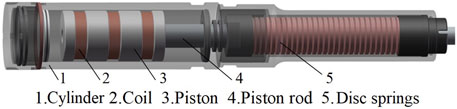
FIGURE 1. MREA structure.
A uniform disc spring (UDS) with a rectangular section is adopted as the restoring mechanism; the parameters are shown in Figure 2. In this work, we designed an MREA with 95 restoring disc springs to satisfy a maximum stroke of 60 mm with 20 mm pre-compression, where the single spring will deform as much as 0.84 mm under the impact if they are uniformly distributed.
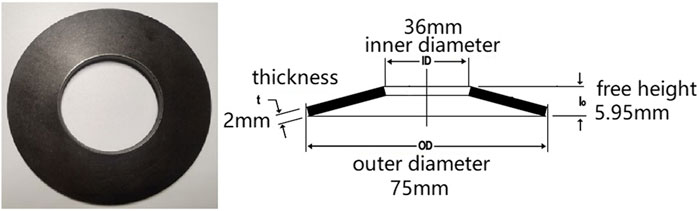
FIGURE 2. Outline and parameters of a piece of disc spring.
An axisymmetric schematic of the magnetorheological valve is shown in Figure 3. It is separated with three coils each 180 turns. Four segments of magnetic yoke with a radius Rp of 44 mm made of pure iron take the role of piston, and the wiring is threaded out of the piston rod in a radius Rr of 16 mm with a center hole of 5 mm in diameter. The cylinder is made of mild steel with a radius Rc of 45 mm, and a flow gap of 1 mm is formed with the piston. When the piston is pulled out of the cylinder under the impact load, the MR fluid is forced flow through the gap under the induced pressure with the relative shear motion between the cylinder and piston, which forms the so-called mixed working mode.
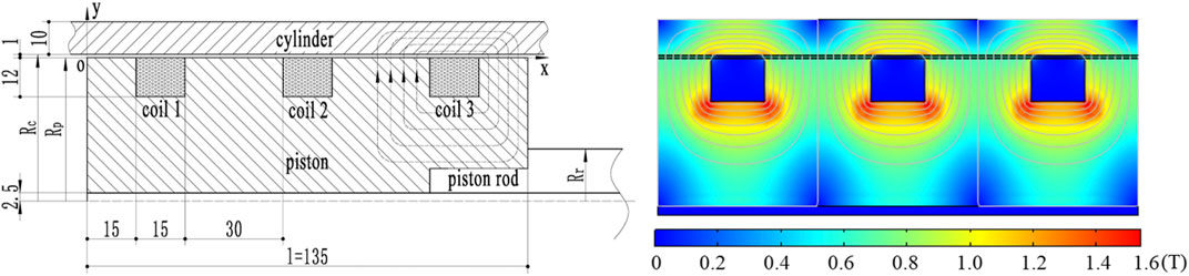
FIGURE 3. Schematic and magnetic distribution of the magnetorheological valve in MREA.
The MR valving principle is somewhat difficult in consideration of MR fluid characteristics, magnetic field distribution, and the transmission from electromagnetic to magnetorheological, but undisputedly, it can be regarded as a valve with the capability of controlling the MR fluid flow between zero field and saturation (Hu et al., 2016). In this research, the piston and the cylinder thickness are sufficiently sized to make a strong enough magnetic induction in the MR gap, and then the maximum shear yielding stress of MR fluid will be applicable. As shown in Figure 3, the average magnetic flux in the gap approaches 0.65 Tesla, which is strong enough for MR fluid to reach its saturation condition. According to the MR effect, MR fluid behaves like a Newtonian fluid in zero field, which can be demonstrated with density
This means that the stimulated MR fluid is capable of bearing static load until the shear yield flow happens, where
The dynamic behaviors of an MREA are complicated because there are many contributing factors. Generally speaking, the total force comprises the damping force resulting from the MR fluid flow and the elastic force of the disc springs; the friction between moving parts and the interaction with volume compensation are always neglected to better understand the rheological mechanism because they are relatively small. Moreover, the averaged magnetic distribution and thus homogeneous MR fluid properties are assumed in the physical modeling.
MR fluid flow in the gap is assumed to be uncompressible and continuous and the gravity effect neglectable; the N-S equations can be expressed as:
Based on the pressure transmission in the gap, the pressure gradient in the gap can be treated as constant, and then:
Where
So,
When the MR fluid is excited, as shown in Figure 4, the flow in the gap can be divided into three layers: the layers of shear yield flow close to the piston and cylinder, called SF-1 and SF-3, and the rigid flow layer RF-2 sandwiched between the shear yield layers. The origin of the coordinate is fixed at the point where the gap flow starts, neighboring the piston surface, but it does not move with the piston. The cylinder is kept static, but the piston is pulled out at the speed of
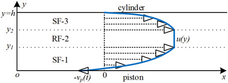
FIGURE 4. The flow profile modeling for MREA.
The MR fluid volume can be calculated as:
The force of the MR valve generated is:
In the quasi-steady modeling of the MR valve, estimation error would result if all the momentum terms related to time and MR fluid density were omitted, which would deviate the experimental results in the preliminary design of a landing gear or anti-recoil system. The MR fluid flow of the three layers can be reanalyzed by considering the momentum terms as follows.
In the SF-1 layer,
Where
Equation 10 is partial differential equation with homogeneous boundary conditions; the variable separation method can be used to transform it into two ordinary differential equations and obtain the solution, where
So, the solution will be
A, B, and C are constants. The boundary conditions apply, and we can obtain:
The general solution of
Substituting the initial condition of
Then, the velocity profile in the SF-1 layer can be expressed as:
In the SF-3 layer,
where
In the RF-2 layer,
We can write the N-S equation again as follows:
We can substitute the velocity profile
Where
So,
Lastly, the MR fluid volume should satisfy that.
where
So,
Two MREAs were manufactured and assembled with the parameters mentioned above. MR fluid was produced by the Chongqing Materials Research Institute; its main parameters are listed in Table 1. Only the maximum shear yielding stress is presented here because the utmost performance of the MREA is concerned.
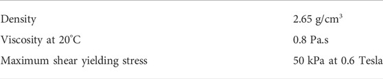
TABLE 1. Parameters of MR fluid.
The disc springs were fabricated by a company in Yangzhou, China, and 50CrVA spring steel was employed to prepare the disk spring samples without heat processing including hardening (Shou et al., 2018). A microcomputer-controlled spring tension and compression tester were utilized to measure the load–deflection relationship of the disk springs and a loading rate of 0.3 mm/s was applied in the testing. Lubricating oil was smeared to reduce the friction between the spring pieces. The deformation parameters were tested but the behavior under the impact was not investigated because of the device limit, so the springs were taken as a linear series combination. The elastic modulus of a single spring was 5.7 kN/mm and about 60 N/mm for the series combination to fulfil a preload of 1.2 kN.
The coils of the MR valve were wrapped manually and the enameled wire with diameter of 0.8 mm was used. The outside layer of the coils was sealed with epoxy resin for isolating and flow smoothing. To ensure the magnetic field between the coils, the three coils were wrapped as clockwise–counter clockwise–clockwise. The finite element analysis was carried out to guarantee that the magnetic flux is strong enough to approach the yielding stress saturation of MR fluid when the current is 3.0 A, which reduces the MREA appraisal into the range determination between saturation and zero field.
A drop test bench illustrated in Figure 5 was prepared for the MREA appraisal. Two MREAs were installed upside-down on the mounting pads at both sides with a connecting crossbeam to accept the impact from a mass block of 120 kg, guided by the column when dropped under gravity. A laser distance measuring instrument was used to record the movement, and two piezoelectric sensors were clamped between the load plates with each MREA. The total force of two MREAs generated in the impact is the sum of the four sensors, and includes the forces from the disc springs and damping force. However, when in zero field, the damping force is purely the viscous damping, but the Coulomb damping force arises when the MREA is powered.
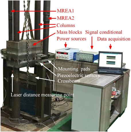
FIGURE 5. Experiments based on the drop test bench.
The MREA works under the impact to avoid too long strokes by heightening the damping force under the control, and the initial impact speeds when the mass block hits the connecting crossbeam were set to 1.5 m/s and 3.0 m/s, fulfilled by adjusting the drop heights of the mass block. To compare the controllability of the MREA, the tests were carried out both at zero field and the saturated excitation at two impact velocities of 1.5 m/s and 3.0 m/s to obtain the total forces by summing four parallel force sensors, and the data are shown in Figure 6.
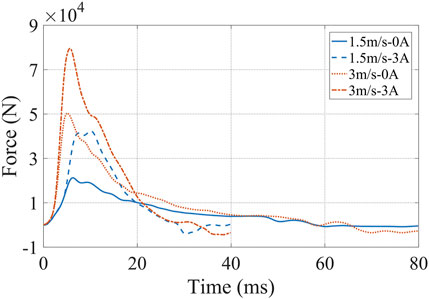
FIGURE 6. The experimental results for MREA at different impact speeds and excitations.
When the MREA is not excited, the total forces at both 1.5 m/s and 3.0 m/s experience a sudden growth and reach their peak at about 5–6 ms where the maximum impact speeds are reached, and then the buffering lasts with a smooth and slow total force decrement. There is a little recoil motion at the end of the buffering process, and the larger the impact speed is, the sooner the peak force reaches and the more apparent the recoil motion will be. When the MREA is excited, the peak force is tremendously heightened, which results quick energy absorption at the early stage of the buffering. In terms of the peak force of the MREA, there is over twofold growth when the impact speed is 1.5 m/s between the saturated current excitation and zero field, and almost 1.6-fold growth at 3.0 m/s impact speed. The growth ratio decreases with the impact speed because the viscous damping force increases while the Coulomb damping force remains constant.
To make a comparison with the experimental results, both the quasi-steady model and its unsteady extension were calculated with MATLAB platform. Figure 7 shows the comparison between the experimental results with the quasi-steady modeling and its unsteady extension at zero field, and the impact speeds are 1.5 m/s and 3.0 m/s, respectively. Because it is in zero field, the yielding stress of MR fluid is zero, and the quasi-steady model is degraded to
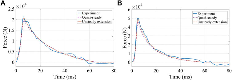
FIGURE 7. The force between the experiments and the models at zero field: (A) 1.5 m/s; (B) 3.0 m/s.
The velocity profile is an asymmetrical parabola in the narrow flow gap because of the shear motion between the walls. In the same way, Eqn. 17 will disappear because the condition of
The same comparison is carried out when the MREA is excited at the saturated condition of the 3.0 A current both in 1.5 m/s and 3.0 m/s, and the results are shown in Figure 8. It is obvious that with impact progress, both the models successfully predict the buffering to zero in shorter time because of more energy absorption compared to zero field. Both models reflect the total force tendency as the experimental results have relatively large errors. The quasi-steady model experiences similar start processes with the experimental tests at the start period of the impact, and then diverges when total forces accumulate because the neglected inertial effect becomes notable. The unsteady extension behaves better to trace the experimental results than the original after taking the inertial effect into consideration, and generally gives out acceptable prediction.
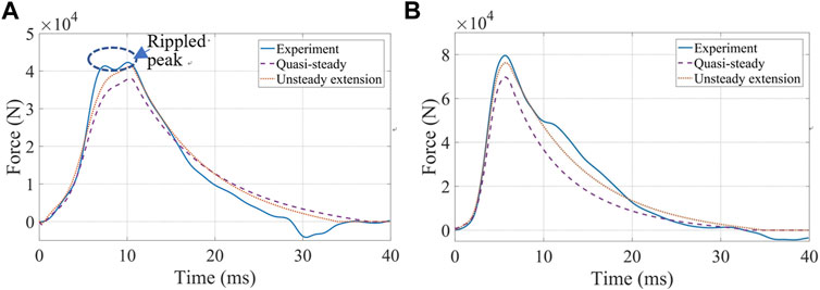
FIGURE 8. The force between the experiments and the models at 3.0 A: (A) 1.5 m/s; (B) 3.0 m/s.
However, it is interesting that a rippled peak, which is shown in Figure 8A, appears for the experimental total force of a fully excited MREA at 1.5 m/s impact speed, whereas a single peak remains at 3.0 m/s impact speed, and this can be explained by the dynamic development of the flow layer modeling. When the MREA buffering starts from the very beginning, the RF-2 layer will be gradually narrowed to allow more MR fluid to go through the magnetic controlled gap. The dynamic development of the flow layer modeling is shown in Figure 9 at the early stage of buffering under the current excitation, where t = 0, t1, t2, and t3 are some typical moments. t = 0 is regarded as the start of the impact when the flow does not happen, and t = t1 is in the development progress of the rigid flow forms. When the impact speed is 1.5 m/s, t = t2 is regarded as the end of flow layer development when the piston reaches its maximum impact speed, where the rigid flow layer remains constant. With the piston speed decreasing and thus the peak flow velocity, the rigid flow layer RF-2 broadens again, and the total force increases again to produce the rippled peak. However, when the impact speed is as high as 3.0 m/s, the rigid flow layer cannot be maintained because the yielding stress of the MR fluid under the magnetic field cannot endure too high shear motion even when the magnetic field is saturated; t = t3 is regarded as the end of flow layer development when the piston reaches its maximum impact speed and the rigid flow layer RF-2 disappears, so the MR fluid behaves more like Newtonian fluid with higher viscosity than in its original state.
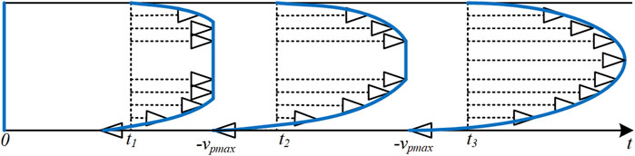
FIGURE 9. Dynamic development of the flow layer modeling for MREA.
To better testify the explanation of the flow layer development, more experimental tests were carried out for the MREA at the saturated current of 3.0 A at different impact speeds. As shown in Figure 10, it is obvious that the rippled peak of the total force appears at the lower impact speed, and with the increase in the impact speed, the rippled peak gradually evolves to a single peak.
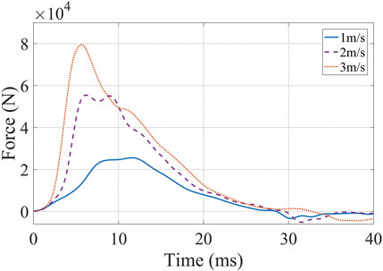
FIGURE 10. Experimental results of excited MREA at 3.0 A and more impact speeds.
Based on the Bingham constitutive model of magnetorheological fluid, we carried out quasi-steady flow modeling to designate the magnetorheological valving for an energy absorber; however, our behavior prediction somewhat deviated from the behavior of the actual device. To better estimate the performance of the magnetorheological energy absorber under impact load by taking the momentum terms into consideration in the flow modeling, the unsteady extension of the quasi-steady model was developed. A magnetorheological energy absorber was actually fabricated with disc springs as the recoiling mechanism and tested on a self-established drop test bench, which produced the impact load by a mass block dropped under gravity, and the impact speed was regulated by the drop height. According to the total force comparison, the unsteady extension of the quasi-steady model estimates the characteristics of the device better than the original. Moreover, the controllability of the magnetorheological energy absorber is fully verified at the conditions of zero field and saturated excitation, and the greater the impact speed is, the lower the controllable ratio will be for the magnetorheological energy absorber because of the larger increase in the uncontrollable Coulomb damping force. Finally, the phenomenon of a rippled peak of the total force is highlighted, and it is explained with the flow modeling that the rigid flow layer is dynamically changing to regulate the peak force of the magnetorheological valving under the saturated excitation, and the rippled peak will disappear if the impact speed is high enough to make the rigid flow layer disappear before the maximum piston speed arrives.
The original contributions presented in the study are included in the article/Supplementary Material, further inquiries can be directed to the corresponding author.
HZ, CL, and NW contributed to conception of the study. NW organized the discussion and drafting. HZ and CL designed the experimental apparatus and took charge of the fabrication. ZZ carried out the modeling, experimental verification and wrote the first draft of the manuscript. HZ provided the project support for the study, revised the manuscript and made the corrections. All authors contributed to manuscript revision, read, and approved the submitted version.
This research was supported by the National Natural Science Foundation of China (no. 62073050).
The authors declare that the research was conducted in the absence of any commercial or financial relationships that could be construed as a potential conflict of interest.
The reviewer XD declared a shared affiliation with the authors to the handling editor at the time of review.
All claims expressed in this article are solely those of the authors and do not necessarily represent those of their affiliated organizations, or those of the publisher, the editors and the reviewers. Any product that may be evaluated in this article, or claim that may be made by its manufacturer, is not guaranteed or endorsed by the publisher.
Bai, X.-X., Wereley, N. M., Choi, Y.-T., and Wang, D.-H. (2012). “A bi-annular-gap magnetorheological energy absorber for shock and vibration mitigation,” in Proc. SPIE 8341, Active and Passive Smart Structures and Integrated Systems 2012. 834123. doi:10.1117/12.917479
Bucchi, F., Forte, P., Frendo, F., Musolino, A., and Rizzo, R. (2014). A fail-safe magnetorheological clutch excited by permanent magnets for the disengagement of automotive auxiliaries. J. Intelligent Material Syst. Struct. 25, 2102–2114. doi:10.1177/1045389x13517313
Du, X., Liao, C., Gan, B., Zhang, Y., Xie, L., and Zhang, H. (2021). Analytical modeling and experimental verification for linearly gradient thickness disk springs. Thin-Walled Struct. 167. doi:10.1016/j.tws.2021.108153
Hu, G., Liao, M., and Li, W. (2016). Analysis of a compact annular-radial-orifice flow magnetorheological valve and evaluation of its performance. J. Intelligent Material Syst. Struct. 28, 1322–1333. doi:10.1177/1045389x16672561
Hu, H., Jiang, X., Wang, J., and Li, Y. (2012). Design, modeling, and controlling of a large-scale magnetorheological shock absorber under high impact load. J. Intelligent Material Syst. Struct. 23, 635–645. doi:10.1177/1045389x12436727
Li, G., and Yang, Z.-B. (2020). Modelling and analysis of a magnetorheological damper with nonmagnetized passages in piston and minor losses. Shock Vib. 2020, 1–12. doi:10.1155/2020/2052140
Li, H., Jönkkäri, I., Sarlin, E., and Chen, F. (2021). Experimental comparison of constitutive models for magnetorheological fluids under different conditions. Braz J. Phys. 51, 1735–1746. doi:10.1007/s13538-021-00989-2
Li, Z. C., and Wang, J. (2012). A gun recoil system employing a magnetorheological fluid damper. Smart Mater. Struct. 21. doi:10.1088/0964-1726/21/10/105003
Mao, M., Hu, W., Choi, Y.-T., Wereley, N. M., Browne, A. L., Ulicny, J., et al. (2013). Nonlinear modeling of magnetorheological energy absorbers under impact conditions. Smart Mater. Struct., 22. doi:10.1088/0964-1726/22/11/115015
Ouyang, Q., Hu, H., Zhao, W., Wang, J., and Li, Z. (2020). Feasibility analysis of magnetorheological absorber in recoil systems: Fixed and field artillery. Front. Mater., 7. doi:10.3389/fmats.2020.00254
Park, J.-Y., Kim, G.-W., Oh, J.-S., and Kim, Y.-C. (2021). Hybrid multi-plate magnetorheological clutch featuring two operating modes: Fluid coupling and mechanical friction. J. Intelligent Material Syst. Struct. 32, 1537–1549. doi:10.1177/1045389x20988086
Powers, B. E., Wereley, N. M., and Choi, Y.-T. (2016). Analysis of impact loads in a magnetorheological energy absorber using a Bingham plastic model with refined minor loss factors accounting for turbulent transition. Meccanica 51, 3043–3054. doi:10.1007/s11012-016-0552-6
Poznic, A., Miloradovic, D., and Juhas, A. (2017). A new magnetorheological brake`s combined materials design approach. J. Mech. Sci. Technol. 31, 1119–1125. doi:10.1007/s12206-017-0210-5
Rizzo, R., Musolino, A., Bucchi, F., Forte, P., and Frendo, F. (2015). A multi-gap magnetorheological clutch with permanent magnet. Smart Mater. Struct., 24. doi:10.1088/0964-1726/24/7/075012
Sheng, C., Zhu, H., and Li, L. (2022). Hybrid vibration control using magnetorheological dampers and elastomers for civil structural. AIP Adv. 12. doi:10.1063/5.0076450
Shou, M., Liao, C., Zhang, H., Li, Z., and Xie, L. (2018). Modeling and testing of magnetorheological energy absorbers considering inertia effect with non-averaged acceleration under impact conditions. Smart Mat. Struct. 27, 115028. doi:10.1088/1361-665x/aae6a0
Wang, H., and Bi, C. (2020). Study of a magnetorheological brake under compression-shear mode. Smart Mater. Struct., 29. doi:10.1088/1361-665x/ab5162
Wang, M., Chen, Z., and Wereley, N. M. (2020). Adaptive magnetorheological energy absorber control method for drop-induced shock mitigation. J. Intelligent Material Syst. Struct. 32, 449–461. doi:10.1177/1045389x20957100
Wang, W., Hua, X., Wang, X., Wu, J., Sun, H., and Song, G. (2018). Mechanical behavior of magnetorheological dampers after long-term operation in a cable vibration control system. Urbana: Structural Control and Health Monitoring, 26. doi:10.1002/stc.2280
Keywords: magnetorheological, energy absorber, quasi-steady modeling, unsteady modeling, experimental verification
Citation: Zou Z, Zhang H, Liao C and Wang N (2022) Unsteady extension of quasi-steady physical modeling and experimental verification of a magnetorheological energy absorber. Front. Mater. 9:942318. doi: 10.3389/fmats.2022.942318
Received: 12 May 2022; Accepted: 27 June 2022;
Published: 15 July 2022.
Edited by:
Zhili Zhang, Beijing Jiaotong University, ChinaReviewed by:
Domenico De Tommasi, Politecnico di Bari, ItalyCopyright © 2022 Zou, Zhang, Liao and Wang. This is an open-access article distributed under the terms of the Creative Commons Attribution License (CC BY). The use, distribution or reproduction in other forums is permitted, provided the original author(s) and the copyright owner(s) are credited and that the original publication in this journal is cited, in accordance with accepted academic practice. No use, distribution or reproduction is permitted which does not comply with these terms.
*Correspondence: Honghui Zhang, aGh6aGFuZ0BjcXUuZWR1LmNu
Disclaimer: All claims expressed in this article are solely those of the authors and do not necessarily represent those of their affiliated organizations, or those of the publisher, the editors and the reviewers. Any product that may be evaluated in this article or claim that may be made by its manufacturer is not guaranteed or endorsed by the publisher.
Research integrity at Frontiers
Learn more about the work of our research integrity team to safeguard the quality of each article we publish.