
95% of researchers rate our articles as excellent or good
Learn more about the work of our research integrity team to safeguard the quality of each article we publish.
Find out more
ORIGINAL RESEARCH article
Front. Mater. , 22 June 2022
Sec. Metamaterials
Volume 9 - 2022 | https://doi.org/10.3389/fmats.2022.937437
This article is part of the Research Topic Transformation Optics and its Frontier Branches View all 11 articles
In this paper, analytical calculation has been provided to show illusion perception in electromagnetics expander. For this end, a precise analytical solution has been done for a scattered wave from the expander including an object in the core medium. Also, this analytical calculation has been done for a bare transformed object with different size and constitute parameters (CPs). Illusion perception, in the far field, can be illustrated by comparing the calculated scattered field patterns (SFP) of the object placed inside the expander with SFP of the bare transformed object. Moreover, the same calculation and comparison has been done for nearfield SFP. In continuation, for precise deduction, radar cross sections (RCSs) of both objects have been calculated and plotted using MATLAB. Well functionality in illusion perception has been obtained using comparisons in both analytical SFPs parts and RCSs parts.
Transformation optics theory (Leonhardt, 2006; Pendry et al., 2006) was introduced in 2006, and since then it has attracted a great deal of scientific attention in theoretical and experimental (Schurig et al., 2006; Chen and Chan, 2007; Chen et al., 2008; Kwon and Werner, 2008; Luo et al., 2008; Rahm et al., 2008; Yan et al., 2008; Chen et al., 2009; Cheng et al., 2009; Lai et al., 2009; Narimanov and Kildishev, 2009; Roberts et al., 2009; Chen et al., 2010a; Chen et al., 2010b; Jiang et al., 2010; Jiang et al., 2011; Li et al., 2011; Mei et al., 2011; Li et al., 2013; Jiang et al., 2014; Sadeghi et al., 2014; Sadeghi et al., 2015a; Sadeghi et al., 2015b; Xu and Chen, 2015; Forouzeshfard and Hosseini Farzad, 2018; Liu et al., 2019; Sadeghi, 2020; Zhao et al., 2022) aspects. This theory applies coordinate transformation and metamaterials to provide desired form variations for the CP to manipulate electromagnetic waves path and direct it in the chosen manner. Hence, this theory provides a great ability to design and construct new composite artificial devices using metamaterials with various extraordinary applications. Among all these different devices, some of them also exhibit interesting illusory optical properties (Lai et al., 2009; Jiang et al., 2010; Li et al., 2011; Forouzeshfard and Hosseini Farzad, 2018; Liu et al., 2019; Sadeghi, 2020; Zhao et al., 2022). In this paper we use analytical calculation for illusion perception in transformation-based expander. For this purpose, in next section we present a transformation function to create and design a wave expander. Next, we provide a close solution in wave expansion form for SFP of an object that has been placed in the core medium of transformation-based expander. In order to show the illusion effect of this device, we compare this SFP of the object inside the expander with the SFP of a transformed bare object. Also, to illustrate the illusion effect more precisely, we provide a comparison in RCSs of both objects. Finally, we provide the conclusion in the end.
We start with a transformation function that expands the region
Where r and
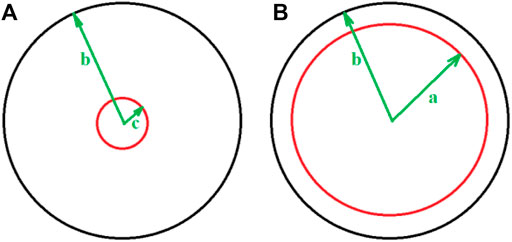
FIGURE 1. schematic functionality of transformation function that expand (A) virtual region [0, c] to (B) real space [0, a].
According transformation optics theory we have CP of core medium i.e.,
Likewise, for surrounding shell i.e.,
Now with these core and shell parameters and using an incidenting TE-z plane wave, the functionality of the device can be plotted as shown in Figure 2. The field distribution pattern of a TE incident plane wave with working frequency 1 GHZ,
In this section we focus on illusion perception using exact solutions in the wave equation of scattering waves. For this end we put a cylindrical object with radius
Consider a TE plane wave propagating in x direction as shown in Figure 3. Hence, we can present wave expansion outside and inside the device using boundary condition (BC). This TE plane wave can be formulated as below,
Where
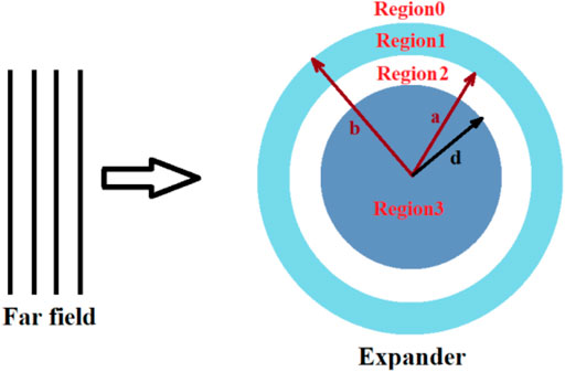
FIGURE 3. Schematic plan for a cylindrical sample with radius
For the electric field outside the device i.e., region0 or
Where
For the core medium i.e., region2, we have the wave as follow,
And finally, for inside the sample i.e., region3, that has been inserted inside the core medium we have,
Where in Eqs 9–11
For continuity of electric fields at
For continuity of electric fields at
And for continuity of electric fields at boundary of object inside the core medium,
We use similar BCs for continuity of magnetic fields at all boundaries.
For continuity of magnetic fields at
For continuity of magnetic fields at
And for continuity of magnetic fields at boundary of object inside the core medium,
Finally, we can obtain the unknown coefficients in all regions with recursive procedure (Cheng et al., 2009) using MATLAB code. Hence, we can plot the electric field in all regions as shown in Figure 4A. Moreover, we can achieve
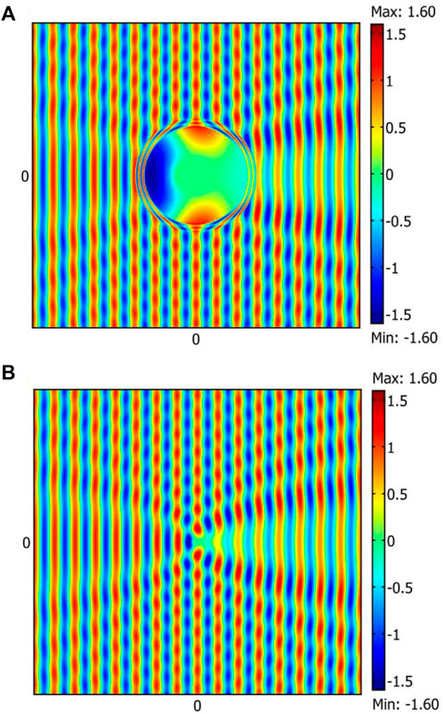
FIGURE 4. (A) SFP of object placed in core medium of expander illuminated by far field, with
Now to comprehend and understand the illusion perception, similar to the scattering calculation for the expander device, we also provide the same calculation for SFP of bare transformed cylinder as shown in Figure 5 with transformed size and CP. For the transformed case we use a bare cylinder with radius
Where
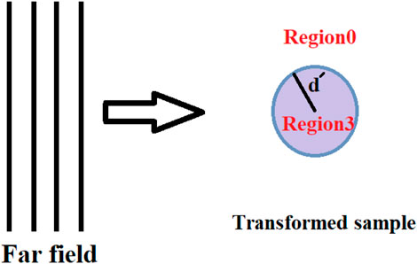
FIGURE 5. Schematic plan for bare transformed cylinder with radius
In this case we have only one interface and for continuity of electric field and magnetic field we can derive matching boundary condition as follow.
For the electric fields at the boundary
And for magnetic fields at the boundary
Similar to calculations in the expander case we calculate the unknown coefficients using recursive code and plot the electric inside and outside of the object as shown in Figure 4B. Illusion perception can be understood by comparing SFP in Figure 4A and SFP in Figure 4B in region
Now for more consideration we also provide the same calculation for illusion perception using near field source. For this part we illuminate both the expander and bare transformed object by a point source located near the device (
For the expander calculation, outside of device, we can derive total electric field as follow.Where
For core region,
And finally, for inside the object,
Similar to far field calculation we use BC for continuity of electric and magnetic field at all interfaces and using recursive method (Cheng et al., 2009) we can derive all unknown parameters and plot the electric field in all regions as showed in Figure 6A.
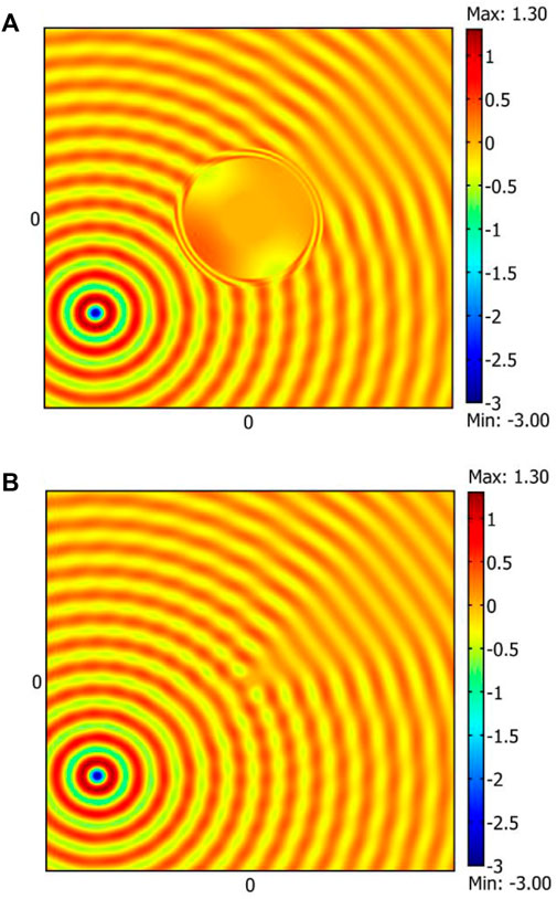
FIGURE 6. (A) SFP of object placed in core medium of expander and illuminated by nearfield with
Likewise, to understand and comprehend the illusion effect we have the same calculation for the bare transformed cylinder that is illuminated by point source. we can calculate the wave outside the cylinder as follow.Where
Similar to far field derivation we use a recursive method to calculate unknown parameters and plot the field inside and outside the cylinder as shown in Figure 6B. Also, illusion perception can be understood by comparing SFP in Figure 6A and Figure 6B i.e., the SFPs in the region
For more precise consideration we provide a qualitative approach. RCS is an indicator of far field scattering, SO, we use RCS plot to compare the both scattering far fields to prove the perfect illusion perception. we use scattering parameters of both object in far field to plot RCS of both scatterers using scattering formula,
We plot the RSCs in Figures 7A, B for expander and bare transformed cylinder, respectively. Both RSCs of samples illustrate the same scattering effects and hence, perfect illusion can be realized.
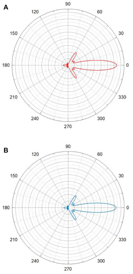
FIGURE 7. (A) RCS (scale of 0.1 m) of a cylinder placed in expander (B) RCS (scale of 0.1 m) of bare transformed cylinder.
Although the wave expander transformation optic-base manipulates electromagnetic wave propagation to expand the wave in core medium, it has some illusory effects that can change the radar cross section of objects. In this paper we used scattering theory to provide full calculations and close solutions to show illusion effects of this device. For this end we compared the scattered waves from both the bare transformed object and object placed in the expander. Moreover, we provided a comparison in RCS for both objects. The results, RCSs and SFPs for both objects, confirmed the perfect illusion effects. Expander illustrates perfect illusion perception in the size of objects.
The raw data supporting the conclusion of this article will be made available by the authors, without undue reservation.
MMS conceived the idea and did the theoretical calculations and the numerical simulations. MMS wrote and revised the manuscript.
The authors declare that the research was conducted in the absence of any commercial or financial relationships that could be construed as a potential conflict of interest.
All claims expressed in this article are solely those of the authors and do not necessarily represent those of their affiliated organizations, or those of the publisher, the editors and the reviewers. Any product that may be evaluated in this article, or claim that may be made by its manufacturer, is not guaranteed or endorsed by the publisher.
Chen, H., Chan, C. T., and Sheng, P. (2010). Transformation Optics and Metamaterials. Nat. Mater 9, 387–396. doi:10.1038/nmat2743
Chen, H., and Chan, C. T. (2007). Transformation Media that Rotate Electromagnetic Fields. Appl. Phys. Lett. 90, 241105. doi:10.1063/1.2748302
Chen, H., Hou, B., Chen, S., Ao, X., Wen, W., and Chan, C. T. (2009). Design and Experimental Realization of a Broadband Transformation Media Field Rotator at Microwave Frequencies. Phys. Rev. Lett. 102, 183903. doi:10.1103/physrevlett.102.183903
Chen, H., Luo, X., Ma, H., and Chan, C. T. (2008). The Anti-cloak. Opt. Express 16, 14603–14608. doi:10.1364/oe.16.014603
Chen, H., Miao, R.-X., and Li, M. (2010). Transformation Optics that Mimics the System outside a Schwarzschild Black Hole. Opt. Express 18, 15183–15188. doi:10.1364/oe.18.015183
Cheng, Y., Xu, J. Y., and Liu, X.-J. (2009). Broadband Acoustic Cloak with Multilayered Homogeneous Isotropic Materials. Piers Online 52, 177–180.doi:10.2529/piers080901204601
Forouzeshfard, M. R., and Hosseini Farzad, M. (2018). Illusion Optics by Single and Twin Cylindrical Cavity Cloaks. Optik 156, 1007–1013. doi:10.1016/j.ijleo.2017.12.053
Jiang, W. X., Ma, H. F., Cheng, Q., and Cui, T. J. (2010). Illusion Media: Generating Virtual Objects Using Realizable Metamaterials. Appl. Phys. Lett. 96, 121910. doi:10.1063/1.3371716
Jiang, X., Liang, B., Zou, X.-Y., Yin, L.-L., and Cheng, J.-C. (2014). Broadband Field Rotator Based on Acoustic Metamaterials. Appl. Phys. Lett. 104, 083510. doi:10.1063/1.4866333
Jiang, Z. H., Gregory, M. D., and Werner, D. H. (2011). Experimental Demonstration of a Broadband Transformation Optics Lens for Highly Directive Multibeam Emission. Phys. Rev. B 84, 1–6. doi:10.1103/physrevb.84.165111
Kwon, D.-H., and Werner, D. H. (2008). Polarization Splitter and Polarization Rotator Designs Based on Transformation Optics. Opt. Express 16, 18731–18738. doi:10.1364/oe.16.018731
Lai, Y., Ng, J., Chen, H., Han, D., Xiao, J., Zhang, Z.-Q., et al. (2009). Illusion Optics: the Optical Transformation of an Object into Another Object. Phys. Rev. Lett. 102, 253902. doi:10.1103/physrevlett.102.253902
Leonhardt, U. (2006). Optical Conformal Mapping. Science 312, 1777–1780. doi:10.1126/science.1126493
Li, C., Liu, X., Liu, G., Li, F., and Fang, G. (2011). Experimental Demonstration of Illusion Optics with “External Cloaking” Effects. Appl. Phys. Lett. 99, 084104. doi:10.1063/1.3629770
Li, L., Huo, F., Zhang, Y., Chen, Y., and Liang, C. (2013). Design of Invisibility Anti-cloak for Two-Dimensional Arbitrary Geometries. Opt. Express 21, 9422–9427. doi:10.1364/oe.21.009422
Liu, Y., Guo, S., and He, S. (2019). Illusion Optics: Disguising with Ordinary Dielectric Materials. Adv. Mater 316, e1805106.
Luo, Y., Chen, H., Zhang, J., Ran, L., and Kong, J. A. (2008). Design and Analytical Full-Wave Validation of the Invisibility Cloaks, Concentrators, and Field Rotators Created with a General Class of Transformations. Phys. Rev. B 77, 125127. doi:10.1103/physrevb.77.125127
Mei, Z. L., Bai, J., and Cui, T. J. (2011). Experimental Verification of a Broadband Planar Focusing Antenna Based on Transformation Optics. New J. Phys. 13, 1367–2630. doi:10.1088/1367-2630/13/6/063028
Narimanov, E. E., and Kildishev, A. V. (2009). Optical Black Hole: Broadband Omnidirectional Light Absorber. Appl. Phys. Lett. 95, 041106. doi:10.1063/1.3184594
Pendry, J. B., Schurig, D., and Smith, D. R. (2006). Controlling Electromagnetic Fields. Science 312, 1780–1782. doi:10.1126/science.1125907
Rahm, M., Schurig, D., Roberts, D. A., Cummer, S. A., Smith, D. R., and Pendry, J. B. (2008). Design of Electromagnetic Cloaks and Concentrators Using Form-Invariant Coordinate Transformations of Maxwell's Equations. Photonics Nanostructures - Fundam. Appl. 6, 87–95. doi:10.1016/j.photonics.2007.07.013
Roberts, D. A., Kundtz, N., and Smith, D. R. (2009). Optical Lens Compression via Transformation Optics. Opt. Express 17, 16535–16542. doi:10.1364/oe.17.016535
Sadeghi, M. M. (2020). Illusion Properties in Perfect Cylindrical Devices. Plasmonics 153, 709–715. doi:10.1007/s11468-019-01088-4
Sadeghi, M. M., Li, S., Xu, L., Hou, B., and Chen, H. (2015). Transformation Optics with Fabry-Pérot Resonances. Sci. Rep. 5, 8680. doi:10.1038/srep08680
Sadeghi, M. M., Nadgaran, H., and Chen, H. (2014). Perfect Field Concentrator Using Zero Index Metamaterials and Perfect Electric Conductors. Front. Phys. 9, 90–93. doi:10.1007/s11467-013-0374-0
Sadeghi, M. M., Xu, L., Nadgaran, H., and Chen, H. (2015). Optical Concentrators with Simple Layered Designs. Sci. Rep. 5, 11015. doi:10.1038/srep11015
Schurig, D., Mock, J. J., Justice, B. J., Cummer, S. A., Pendry, J. B., Starr, A. F., et al. (2006). Metamaterial Electromagnetic Cloak at Microwave Frequencies. Science 314, 977–980. doi:10.1126/science.1133628
Xu, L., and Chen, H. (2015). Conformal Transformation Optics. Nat. Phot. 9, 15–23. doi:10.1038/nphoton.2014.307
Yan, M., Yan, W., and Qiu, M. (2008). Cylindrical Superlens by a Coordinate Transformation. Phys. Rev. B 78, 125113. doi:10.1103/physrevb.78.125113
Keywords: illusion optics, radar cross section, electromagnetics wave expander, scattering theory, transformation optics
Citation: Sadeghi MM (2022) Radar Cross Section Approach in Illusion Effects of Transformation Optics-Based Expander. Front. Mater. 9:937437. doi: 10.3389/fmats.2022.937437
Received: 06 May 2022; Accepted: 06 June 2022;
Published: 22 June 2022.
Edited by:
Fei Sun, Taiyuan University of Technology, ChinaReviewed by:
Shuomin Zhong, Ningbo University, ChinaCopyright © 2022 Sadeghi. This is an open-access article distributed under the terms of the Creative Commons Attribution License (CC BY). The use, distribution or reproduction in other forums is permitted, provided the original author(s) and the copyright owner(s) are credited and that the original publication in this journal is cited, in accordance with accepted academic practice. No use, distribution or reproduction is permitted which does not comply with these terms.
*Correspondence: Mohammad Mehdi Sadeghi, U2FkZWdoaUBqYWhyb211LmFjLmly
Disclaimer: All claims expressed in this article are solely those of the authors and do not necessarily represent those of their affiliated organizations, or those of the publisher, the editors and the reviewers. Any product that may be evaluated in this article or claim that may be made by its manufacturer is not guaranteed or endorsed by the publisher.
Research integrity at Frontiers

Learn more about the work of our research integrity team to safeguard the quality of each article we publish.