 Wei He
 Qing Ouyang
 Hongsheng Hu
 Xudan Ye3
94% of researchers rate our articles as excellent or good
Learn more about the work of our research integrity team to safeguard the quality of each article we publish.
Find out more
ORIGINAL RESEARCH article
Front. Mater. , 28 September 2022
Sec. Smart Materials
Volume 9 - 2022 | https://doi.org/10.3389/fmats.2022.933076
This article is part of the Research Topic Characterization and Application of Magneto-sensitive Soft Materials View all 20 articles
The purpose of this study was to solve the problem that the damping of rubber or silicone oil torsional dampers used in crankshafts is not adjustable and cannot effectively control torsional vibration at different resonant frequencies. Based on the controlled rheological properties of magnetorheological (MR) smart materials, this study designed a new type of variable damping MR torsional damper (MRTD) and proposed a semi-active control method to effectively control the torsional vibration of the crankshaft under multiple harmonic resonances. First, a mechanical model of the MRTD and a lumped parametric mass model of the crankshaft system were developed, and the resonance frequency harmonic range of the crankshaft system operation was determined by the torsional vibration characteristics analysis. Then a semi-active skyhook control method for the MRTD was proposed, and a joint control simulation analysis was performed using Amesim and Matlab software. The torsional vibration control effects of the crankshaft system with no damper, MRTD with different damping coefficients, and MRTD with skyhook control under acceleration and uniform speed conditions were comprehensively investigated. The simulation results indicated that the skyhook damping control significantly reduced the torsional vibration amplitude under both acceleration and uniform speed conditions, verifying the effectiveness of the skyhook-based control strategy for MRTD.
The crankshaft system is subjected to periodic inertia moment, which causes torsional vibration of the crankshaft (Xiong 2019). Severe torsional vibration will lead to fatigue damage of the crankshaft (Sun et al., 2016), wear of meshing gears (Shen et al., 2018), harmful noise (Zhong et al., 2020), and loss of transmission energy (Zhang 2013). Therefore, effective torsional vibration suppression measures should be adopted to control the torsional vibration of the crankshaft in a suitable range to ensure the reliability of the system.
Currently, passive vibration dampers, such as silicone oil viscous dampers (Li and Zhang 2020; Venczel et al., 2021a; Venczel et al., 2021b) and rubber dampers (Penkov 2008; Ning et al., 2013; Willenborg and Kroger 2017), are usually adopted to protect the engine camshaft and crankshaft from the possible damage caused by torsional vibrations and help to avoid the barred speed ranges. The vibration energy is converted into heat, which then dissipates from the damper’s surface into the ambient air. In addition, some studies have put forward compound or hybrid vibration reduction methods on the basis of the abovementioned facts. Yu (2003) designed a torsional-bending composite rubber damper, and Haşmet. (2021) used a hybrid damping method to optimize the design of the damper for damping, which illustrates that a hybrid damping method is more effective than a single damping method.
However, after the design of the passive torsional damper is completed, the dynamic parameters, including damping and stiffness, will be fixed (Ngoc et al., 2018). It means that the deviation of processing and installation technology, the temperature-dependent performance decay, and other factors, may cause problems such as poor performance matching between the designed torsional dampers and crankshaft system and narrow tuning range (Sinyayski 2019). The damper based on magnetorheological fluid (MRF) intelligent material has the excellent characteristics of adjustable damping, wide dynamic range, fast response, and low power consumption (Deng et al., 2022) and is widely used in various intelligent vibration suppression applications (Ahamed et al., 2016; Lin and Jheng 2017; Krauze et al., 2018; Zhou et al., 2021), including crankshaft torsional vibration damper. As for the magnetorheological torsional damper (MRTD), many scholars have performed relevant research and exploration works. Wang et al. (2018) studied the torsional vibration control method of engine/helicopter, which effectively suppressed torsional vibration. Philipp et al. (2017) carried on the simulation optimization design to the torsional vibration damper. Ye and Williams (2005) studied the torsional vibration control of MRF brake and proposed a new torsional vibration control method. In addition, Dong et al. (2020) designed a variable damping and variable stiffness torsional damper, which effectively suppressed the torsional vibration of the vehicle transmission system. But less research work has been conducted on the engine torsional vibration of crankshaft systems, and several of the research works have focused on the design of structural components for torsional dampers (Christopher 1992; Shook 2008; Abouobaia et al., 2015); there are few studies on control strategies. Thus, how to design a reasonable and effective control strategy to realize adaptive vibration control of the crankshaft system is of great significance.
In this study, the principle and structural mechanics of a variable damping torsional damper are analyzed, and a torsional vibration model of the crankshaft system is developed for engine crankshaft torsional vibration. In addition, Amesim and Matlab are used for co-simulation, and the torsional vibration of the crankshaft under various working conditions is discussed. The vibration of the crankshaft with and without dampers installed at the free end of the crankshaft and the influence of the damping coefficient on the torsional vibration of the crankshaft are studied. Finally, the skyhook damping semi-active control method is proposed, and simulation results show that it has a preferable damping effect and also provides a theoretical basis for the design of future crankshaft system control methods.
The MRTD studied in this research study adopts a vibration-absorbing mode of operation. Based on the theoretical analysis of the engine crankshaft system torsional vibration model, the crankshaft system is equivalently transformed into a single-degree-of-freedom undamped system with a torsional damper attached to the shaft end to form a double torsional pendulum system (Hoang 2013), and the natural frequency and system energy of the system before and after simplification remain unchanged. The equivalent model diagram of the double torsional pendulum system is shown in Figure 1. The response characteristics of each dynamic parameter to the crankshaft torsional vibration system are analyzed, and the setting principle of those parameters in the device design is discussed so as to achieve the minimum torsional vibration response amplitude of the crankshaft system.
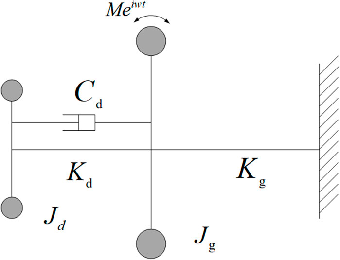
FIGURE 1. Equivalent model diagram of the double torsion pendulum system.
An MRTD is installed at the free end of the crankshaft to achieve the desired damping state by controlling the current and varying the damping coefficient. The mechanical equations of the model are shown in Eq. 1.
Eq. 1 is the external disturbance moment;
where
In the above equations,
The amplification factor of torsional vibration R is the ratio of the static variable of the crankshaft system to the amplitude of the shafting main vibration system; the expression is shown in Eq. 7.
where
As can be seen from Eq. 7, for the amplification factor of torsional vibration, the damping effect of the crankshaft system with the crankshaft torsional damper installed is mainly determined by inertia ratio, setting ratio, and damping ratio. The greater the dynamic amplification factor, the more violent the vibration. The effect of these three factors on torsional vibration can be seen in Figure 2.
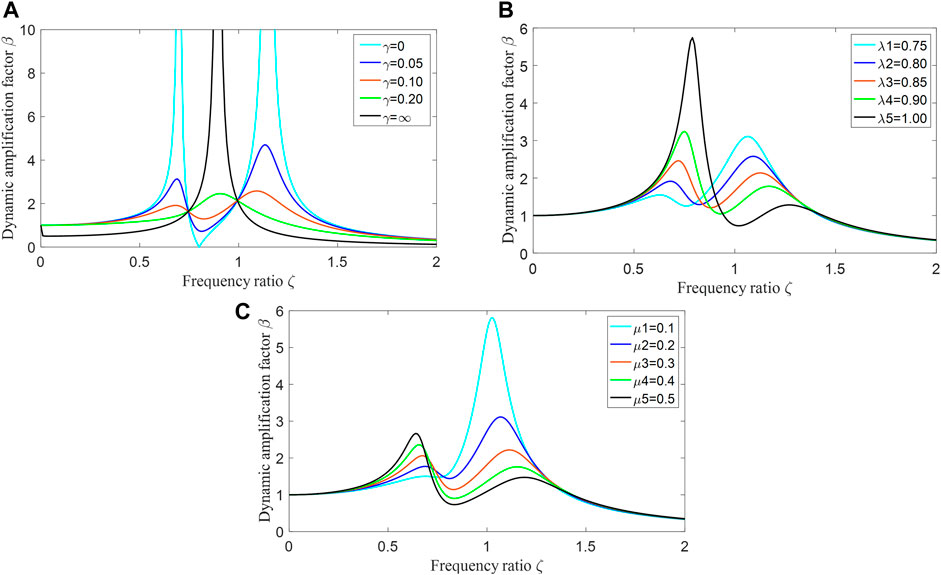
FIGURE 2. Parametric analysis of torsional dampers; (A) Damping ratio; (B) Fixed ratio; (C) Inertia ratio.
The damping ratio, inertia ratio, and setting ratio of the torsional damper have an obvious effect on the dynamic amplification factor of the crankshaft system. Since the inertia ratio and setting ratio are determined during device design, the damping ratio needs to be changed to attenuate the vibration. Therefore, it is required to design an effective control method to output the optimal damping in real-time.
In the MRTD structure design, the crankshaft MRTD designed in this study is a disc-type structure of the damper. The structure includes the shell, end cover, and inertia block, as shown in Figure 3, where the yellow part is the magnetic induction line. The free end of the crankshaft is connected to the outer casing of the MR damper, and the outer casing and inertia block are filled with MRF. The outer shell is fixed at the free end of the crankshaft, and when working, torsional vibration occurs with the shafting. Owing to the inertia block and the outer shell not being directly connected, it keeps uniform rotation under the influence of its own inertia. At this time, the outer shell moves relative to the inertia block, and the energy of torsional vibration is consumed by adjusting the appropriate damping due to the filling of magnetorheological fluid. When the current is changed, the magnetic field in the MR damper changes, and thus the damping of the MRF change to achieve the effect of vibration control. The basic parameters of MRTD are damping: 0.00427
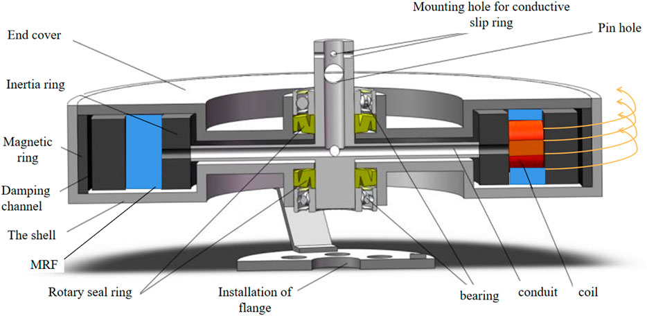
FIGURE 3. MRTD model diagram.
When applying MRF to semi-active control, a suitable parametric model is required due to its strong non-linear and hysteretic characteristics. The hyperbolic tangent model used in this study has the advantages of simple structure, easy identification of model parameters, and easy solution of the inverse model. The damping force expression is as in Eq. 8.
where
In this study, relevant data are used to identify and fit the parameters of the model, and the nonlinear relationship between current and parameters is obtained (Dong et al., 2020). As shown in Figure 4, after obtaining the complete mechanical equation, the output of the relationship between the current and the damping force is used to pave the way for the damping control of the MRTD later, and the mathematical model is established to lay the foundation for the design of the control algorithm later.
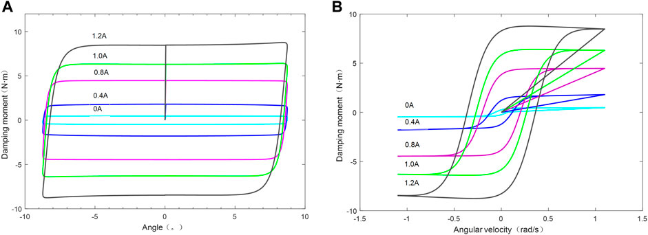
FIGURE 4. Mechanical characteristics of MRTD; (A) Angular rotation; (B) Angular velocity.
To model the corresponding dynamics of torsional vibrations in the crankshaft system, an MRTD is installed at the free end of the crankshaft, as shown in Figure 5. When the engine crankshaft is working, the damping of MRTD is adjusted by changing the current so as to change the natural frequency of the crankshaft system and achieve the effect of frequency shift to weaken the resonance of the crankshaft when it is working.
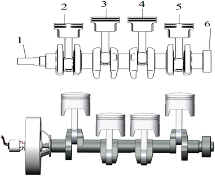
FIGURE 5. Schematic diagram of the crankshaft system (top). Schematic diagram of the crankshaft system with MR damper installed (bottom). 1. Free end of crankshaft 2. First cylinder piston 3. Second cylinder piston 4. Third cylinder piston 5. Fourth cylinder piston 6. Flywheel.
For the analysis of the dynamics of the crankshaft system, this study establishes a concentrated mass model of the crankshaft system. This model has the advantages of simplified component calculation and small deviation of model calculation results, so it is widely used. The model is shown in Figure 6. According to the principle of energy conservation, the crankshaft system is simplified to an equivalent system consisting of an inelastic inertia disc and a massless elastic shaft.
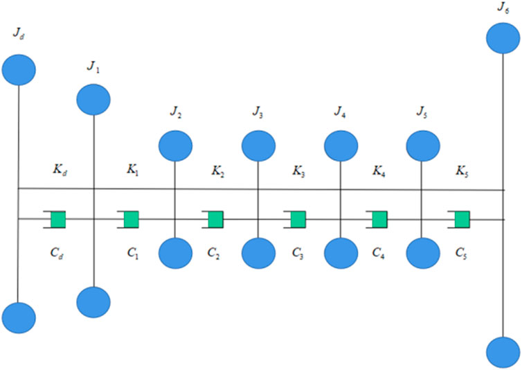
FIGURE 6. Equivalent model of crankshaft system torsional vibrations.
Simplification of elastic, inertial, and damping variables according to the equivalent model of torsional vibration of the crankshaft system, the following kinetic equation can be obtained:
In the equation established from the model,
The above differential equation is represented by the matrix as
In Eq. 10,
In order to better study the torsional vibration characteristics, the free vibration and forced vibration of crankshaft systems are analyzed. In this study, a simplified calculation is performed according to the parameters of a certain four-cylinder engine. The required inertia and stiffness parameters of the crankshaft system are shown in Table 1. The general free mode is only related to the rotational inertia and torsional stiffness, so the damping parameters are not used in solving the free vibration.
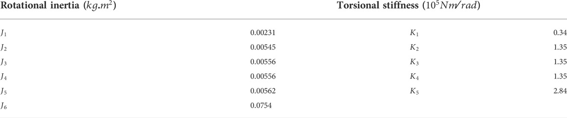
TABLE 1. Main parameters of the crankshaft system.
According to Eqs 1 and 2 and the values of each parameter in Table 1, the inherent frequencies of the free vibration of the crankshaft system can be calculated, and the modal diagram of the inherent frequencies can be obtained by using MATLAB simulation, The first five inherent frequencies are shown in Table 2.
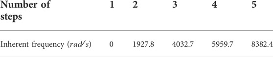
TABLE 2. Intrinsic frequency values of the crankshaft system.
The calculated modal diagram for the first five inherent frequencies of the crankshaft system is shown in Figure 7.
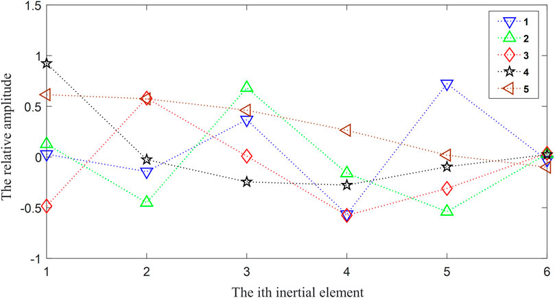
FIGURE 7. Modal diagram.
As can be seen from the vibration pattern diagram, in the first three orders of the inherent frequency, 2, 3, 4, 5, these mass points’ vibration pattern amplitude change more. Therefore, when the excitation frequency of the system and the inherent frequency are the same, the vibration caused by crankshaft resonance can cause damage to components, which will affect the service life of the crankshaft.
By establishing the differential equations for a simplified parametric model of the crankshaft system fitted with an MRTD, the inherent frequency of the crankshaft system fitted with the MRTD is calculated using the previous calculation method, and the harmonic order of its resonance is solved. The first four orders of the solved inherent frequencies are as follows.
According to the natural vibration frequency of the engine crankshaft, the resonance speed of the crankshaft can be obtained. That is, the external disturbance torque causing resonance is determined jointly with the working speed of the engine. The calculation for determining the harmonic times
where
Taking the engine’s operating speed range of the minimum speed as
When the number of resonant harmonic moments increases, the vibration amplitude decreases. Therefore, for the higher harmonic times (12 times or more) of the shaft resonance, the resonance amplitude caused is relatively small, and the harm caused to the crankshaft is not significant, so it is not considered for the time being.
This research work studies a four-cylinder engine, and its working range is 2000–5000 rpm. Through the torsional vibration analysis of the engine crankshaft system, it is found that the harmonic moment of the second natural frequency is the main harmonic order that causes the resonance. From Eq. 13, we can calculate the harmonic range of resonance is 2–12 harmonics. From this, we can calculate the critical speed of resonance; when the engine speed is the same as the critical speed, resonance will occur. So, the resonance should be different damping forces for different harmonics outputs to effectively reduce the crankshaft resonance.
The skyhook damping control strategy has an important place in the control strategy of semi-active suspensions and is the most commonly used control strategy in MR semi-active control. It is a classical method of semi-active suspension control proposed by Karnopp et al. in 1974. It has the characteristics of simple principle, easy implementation, and good robustness and is often used to compare with new control methods. The method is to install a damper between the reeded mass block and the virtual sky, taking the vertical vibration velocity of the reeded mass block as the object of study, and the damper generates a damping force opposite to the velocity of the reeded mass block. The model is based on a passive suspension for design, as shown in Figure 8.Here,
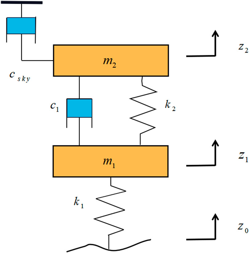
FIGURE 8. Diagram of the skyhook damping control model.
The kinetic model is
where
The force
where
Our actual control is to give the magnitude of the input current to the MR dampers; here, we simply give the current as 0 or
The control process for crankshaft torsional vibration is through the acquisition of real-time vibration signals from the free end of the crankshaft after the controller’s data analysis and calculation to output a reasonable corresponding current. Then, the MRTD after the current is connected to output the corresponding damping force to achieve effective vibration damping. Thus, with the MRTD employing skyhook damping control, the block diagram of the control system is shown in Figure 9.
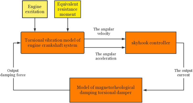
FIGURE 9. Block diagram of crankshaft torsional vibration control.
The kinetic model is built from the established parametric equations using Amesim software to obtain the free end vibration curve more directly. The excitation signal of the model outputs the pressure torque according to the ignition sequence of the four-cylinder engine 1-3-2-4. The angular velocity and acceleration of the crankshaft free end during torsional vibration are then simulated and analyzed as the MRTD damping is controlled.
A comparison of the angular velocity and angular acceleration of the free end of the crankshaft system with the MRTD installed and without the torsional damper under accelerating conditions is shown in Figure 10, which shows that the torsional vibration of the crankshaft is effectively suppressed by the installation of the MR damper.
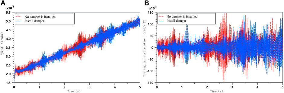
FIGURE 10. Comparison of vibration with and without torsional dampers; (A) Crankshaft angular velocity; (B) Crankshaft angular acceleration.
With an MRTD installed on the engine crankshaft, the damping coefficient can be adjusted by controlling the current to control the vibration of the crankshaft at different harmonic levels. When the damping coefficient of the MRTD is 0 and the damping coefficient is 4, the vibration signals of the free end of the crankshaft at acceleration and constant speed can be obtained, as shown in Figures 11 and 12. The dynamics of the model can be seen clearly in the angular acceleration and angular velocity of the free end of the crankshaft system at different damping factors. At the same time, in acceleration mode, Fourier transform is applied to vibration signals of free end speed and angular acceleration of crankshaft under different damping coefficients to obtain a frequency domain analysis diagram.
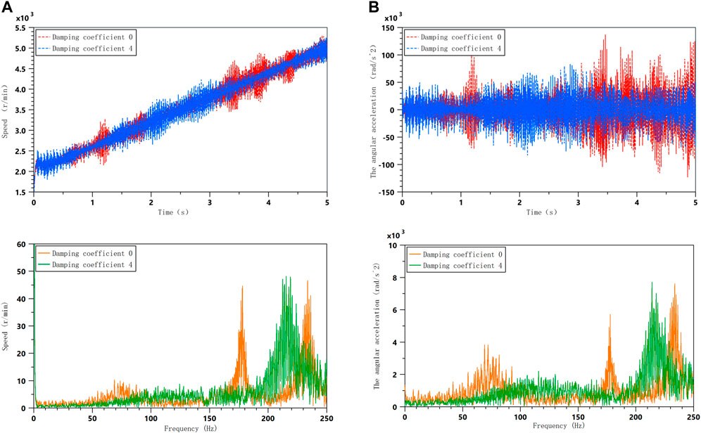
FIGURE 11. Comparison of vibration with different damping factors during acceleration; (A) Crankshaft angular velocity; (B) Crankshaft angular acceleration.
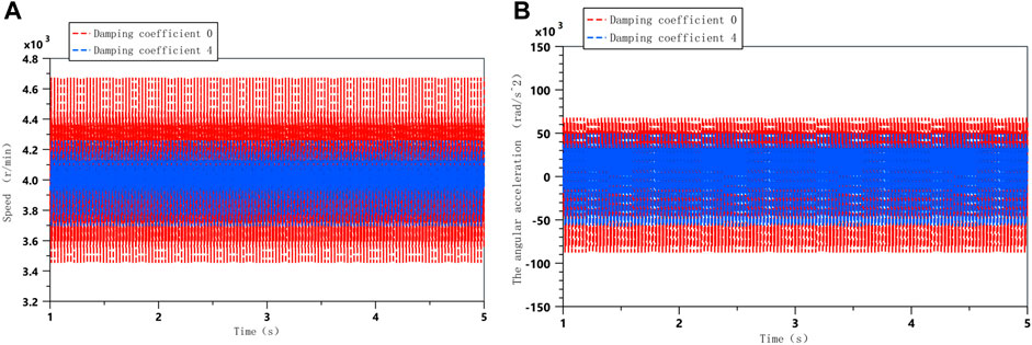
FIGURE 12. Comparison of vibrations with different damping factors at constant speed; (A) Crankshaft angular velocity; (B) Crankshaft angular acceleration.
The time domain analysis diagram shows that when the damping factor is 4, some of the resonance of the crankshaft during acceleration is weakened, which verifies the effective damping performance of the damper. However, according to the frequency domain diagram, it can also be found that during acceleration, the resonance is shifted, and the overall vibration is not effectively suppressed. This is due to the fact that the damping is not optimal at this point in time; so, in order to effectively suppress the resonance of the crankshaft system during acceleration, the optimal damping needs to be calculated for the main resonance frequencies.
A joint simulation using Matlab and Amesim was also used to verify the crankshaft system torsional vibration response under the skyhook damping control strategy at acceleration conditions. This is shown in Figure 13.
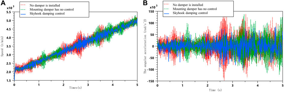
FIGURE 13. Comparison of simulation results for acceleration conditions; (A) Comparison of free end speeds of crankshaft systems under acceleration conditions; (B) Comparison of angular acceleration at the free end of the crankshaft system under acceleration conditions.
The free end torsional vibration of the crankshaft system under steady running conditions is also compared using skyhook damping control, as shown in Figure 14.
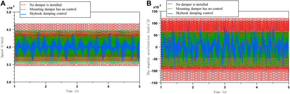
FIGURE 14. Comparison of simulation results for uniform speed conditions; (A) Comparison of free end speeds of crankshaft systems at constant speed; (B) Comparison of angular acceleration at the free end of the crankshaft system under uniform speed conditions.
As can be seen from the simulation analysis graph, the skyhook damping control is significantly more effective than the passive control, effectively suppressing the angular velocity and angular acceleration amplitude of the crankshaft free end vibration near the resonance frequency under acceleration conditions. The skyhook damping control also reduces the torsional vibration response to a certain extent during the smooth running phase.
Based on the abovementioned simulation results, the peak and RMS (root mean square) values of the angular velocity fluctuation at the free end of the crankshaft and the angular acceleration
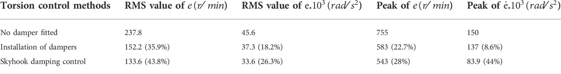
TABLE 3. Peak and RMS values of torsional vibration response for acceleration condition.
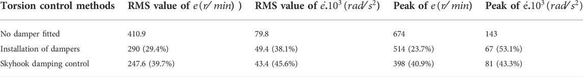
TABLE 4. Peak and RMS values of torsional vibration response for uniform speed conditions.
As can be seen from the tables mentioned earlier, the skyhook damping control is able to significantly reduce the RMS value of the angular velocity fluctuations at the free end of the crankshaft and the angular acceleration fluctuations by 43.8 and 26.3%, respectively, as well as reducing the peak value by 28 and 44%, respectively, when compared to the passive control during acceleration conditions.
The tables show that the skyhook damping control is also superior to the passive control method under uniform speed conditions, with a reduction of 39.7 and 45.6% in the RMS value of the angular velocity and angular acceleration fluctuations, respectively, and a peak value of 40.9 and 43.3% for their fluctuations, respectively. The results of the abovementioned analysis also validate the effectiveness of the semi-active control of skyhook torsion.
The MRTD of the variable-damping crankshaft system has been studied in this article. In order to improve the smoothness and stability of the crankshaft system, the application of the dynamics model and the skyhook damping control method were investigated through analytical calculations and numerical simulations. The following conclusions were obtained.
(1) The damping ratio, inertia ratio, and setting ratio of the MRTD have a relatively obvious influence on the dynamic amplification coefficient of the crankshaft system. After the structural parameters of the device have been determined, the damping ratio can be controlled to achieve effective torsional damping of the crankshaft system.
(2) Through the simulation analysis of the constant damping torsional damper, when the damping coefficient increases, the torsional amplitude of the crankshaft system decreases in a certain range under the conditions of acceleration and constant velocity. At the same time, the resonance frequency of the system is changed to achieve the effect of frequency shift. It can be seen that the torsional vibration of the crankshaft can be inhibited obviously by changing the damping coefficient of the torsional damper.
(3) The design of a skyhook damping control method to control the MRTD through the simulation of comparative analysis shows that the control method in the acceleration conditions crankshaft speed fluctuations e and angular acceleration fluctuations in the RMS and peak reductions of 43.8 and 26.3 and 28% and 44%, respectively. The RMS and peak reductions of crankshaft speed fluctuation e and angular acceleration fluctuation at constant speed are 39.7 and 45.6 and 40.9 and 43.3%, respectively, which shows that the skyhook damping control has a better damping effect than the constant damping.
The research is mainly based on theoretical analysis and simulations, but future experiments are needed to validate the results and further incorporate new intelligent control algorithms.
The original contributions presented in the study are included in the article/Supplementary Material; further inquiries can be directed to the corresponding author.
Reviewing, guidance, and support: QO and HH; Modeling, simulation, and original draft preparation: WH; Data analysis and simulation results analysis: WH, XY, and LL.
This work was supported by the Zhejiang Provincial Natural Science Foundation of China (Grant Nos. LGG20E050022 and LGG19E050017) and in part by the National Natural Science Foundation of China (NSFC) grant funded by the Chinese Government (Grant No. 51805209) and the Jiaxing Municipal Science and Technology Project (Grant No. 2020AY10036).
Author LL was employed by Ningbo Sedsun Vibration Damper Co., Ltd. OQ works at Jiaxing University and has done postdoctoral research at Nanjing University of Science and Technology and Taizhou Jiuju Technology Co., Ltd.
The remaining authors declare that the research was conducted in the absence of any commercial or financial relationships that could be construed as a potential conflict of interest.
All claims expressed in this article are solely those of the authors and do not necessarily represent those of their affiliated organizations, or those of the publisher, the editors, and the reviewers. Any product that may be evaluated in this article, or claim that may be made by its manufacturer, is not guaranteed or endorsed by the publisher.
Abouobaia, E., Bhat, R., and Sedaghati, R. (2015). Development of a new torsional vibration damper incorporating conventional centrifugal pendulum absorber and MR damper. J. Intelligent Material Syst. Struct. 27 (7), 980–992. doi:10.1177/1045389X15590275
Ahamed, R., Ferdaus, M. M., and Li, Y. C. (2016). Advancement in energy harvesting magneto-rheological fluid damper: A review. Korea-Aust. Rheol. J. 28 (4), 355–379. doi:10.1007/s13367-016-0035-2
Christopher, S. K. (1992). Prediction and control of heavyduty powertrain torsional vibration. J. Commer. Veh. 1992, 805–814.
Deng, L., Sun, S., Christie, M., Ning, D., Jin, S., Du, H., et al. (2022). Investigation of a seat suspension installed with compact variable stiffness and damping rotary magnetorheological dampers. Mech. Syst. Signal Process. 171, 108802. doi:10.1016/j.ymssp.2022.108802
Dong, X. M., Li, W. F., Yu, J., Pan, C., Xi, J., Zhou, Y., et al. (2020). Magneto-rheological variable stiffness and damping torsional vibration control of powertrain system. Front. Mat. 7, 121. doi:10.3389/fmats.2020.00121
Haşmet, Ç., and Tinkir, M. (2021). Optimization of torsional vibration damper of cranktrain system using a hybrid damping approach. Eng. Sci. Technol. Int. J. 24 (4), 959–973. doi:10.1016/j.jestch.2021.02.008
Hoang, N., Zhang, N., Li, W. H., and Du, H. (2013). Development of a torsional dynamic absorber using a magnetorheological elastomer for vibration reduction of a powertrain test rig. J. Intelligent Material Syst. Struct. 24 (16), 2036–2044. doi:10.1177/1045389x13489361
Krauze, P., Kasprzyk, J., Kozyra, A., and Rzepecki, J. (2018). Experimental analysis of vibration control algorithms applied for an off-road vehicle with magnetorheological dampers. J. Low Freq. Noise Vib. Act. Control 37 (3), 619–639. doi:10.1177/1461348418756018
Li, M. M., Zhang, J. Y., Wu, C., Zhu, R., Chen, W., Duan, C., et al. (2020). Effects of silicone oil on stiffness and damping of rubber-silicone oil combined damper for reducing shaft vibration. IEEE ACCESS 8, 218554–218564. doi:10.1109/access.2020.3041359
Lin, C. Y., and Jheng, H. W. (2017). Active vibration suppression of a motor-driven piezoelectric smart structure using adaptive fuzzy sliding mode control and repetitive control. Appl. Sci. (Basel). 7 (3), 240. doi:10.3390/app7030240
Ngoc, M. V., Shin, S. C., and Kim, G. W. (2018). Comparative study on non-traditional torsional vibration isolators for automotive clutch dampers. Noise Control Eng. J. 66 (6), 541–550. doi:10.3397/1/376645
Ning, S. K., Jia, L., and Ma, B. J. (2013). Optimization model of metal rubber buffer on artillery. Front. Manuf. Des. Sci. III, 271237–271241. doi:10.4028/www.scientific.net/amm.271-272.237
Penkov, B. (2008). A method for modeling the shock of a rubber buffer with a rigid body. Transport 23 (2), 119–123. doi:10.3846/1648-4142.2008.23.119-123
Philipp, M., Fidlin, A., Kruger, A., and GroB, H. (2017). Simulation based optimization of torsional vibration dampers in automotive powertrains. Mech. Mach. Theory 115, 244–266. doi:10.1016/j.mechmachtheory.2017.05.010
Shen, Z. X., Qiao, B. J., and Chen, X. F. (2018). “The influence of external spur gear surface wear on the mesh stiffness,” in 2018 Prognostics and System Health Management Conference (PHM-Chongqing), Chongqing, China, 26-28 October 2018 (IEEE), 1232–1238.
Shook, D. A. (2008). Semi-active control of torsion ally-responsive structures. Eng. Struct. 31, 57–68. doi:10.1016/j.engstruct.2008.06.016
Sinyayski, V. V. (2019). “Results of simulation and experimental research of automobile gas diesel engine,” in Systems of Signals Generating and Processing in The Field of On Board Communications, Moscow, Russia, 20-21 March 2019 (IEEE).
Sun, J., Shu, L., Song, X., Liu, G., Xu, F., Miao, E., et al. (2016). Multi-objective optimization design of engine crankshaft bearing. Industrial Lubr. Tribol. 68 (1), 86–91. doi:10.1108/ilt-03-2015-0040
Venczel, M., Bognar, G., and Veress, A. (2021b). Temperature-dependent viscosity model for silicone oil and its application in viscous dampers. Processes 9 (2), 331. doi:10.3390/pr9020331
Venczel, M., Steidl, M., and Veres, A. (2021a). Design modifications and thermal analysis of visco-dampers for extending silicone oil durability. Acta Polytech. Hung. 18 (8), 27–46. doi:10.12700/aph.18.8.2021.8.2
Wang, Y., Zheng, Q. G., Zhang, H., and Miao, L. Z. (2018). Adaptive control and predictive control for torsi-onal vibration suppression in helicopter/engine system. IEEE ACCESS 6, 23896–23906. doi:10.1109/access.2018.2829723
Willenborg, D., and Kroger, M. (2017). Isolation and damping properties of rubber-buffers. Const. Models Rubber X, 477–482. doi:10.1201/9781315223278-74
Xiong, J. Q. (2019). Research on subjective rating attenuation analysis of automobile NVH characteristics. Procedia Comput. Sci. 154, 383–388. doi:10.1016/j.procs.2019.06.055
Ye, S., and Williams, K. A. (2005). Torsional vibration control with an MR fluid brake. Proc. Spie 5760, 283–292. doi:10.1117/12.600174
Zhang, L. R. (2013). Brief analysis of torsional vibration of vehicle engine. Adv. Mat. Res. 1-4, 302–306. doi:10.4028/www.scientific.net/amr.694-697.302
Zhong, Y. X., Yang, D. L., and Hui, H. (2020). “Driveline torsional vibration analysis and research of a light van,” in 5Th International Conference on Information Science, Computer Technology and Transportation (ISCTT 2020), Shenyang, China, 13-15 November 2020 (IEEE), 554–557.
Keywords: magnetorheological fluid, torsional damper, crankshaft system, semi-active control, skyhook damping control
Citation: He W, Ouyang Q, Hu H, Ye X and Lin L (2022) Semi-active control of crankshaft skyhook based on magnetorheological torsional damper. Front. Mater. 9:933076. doi: 10.3389/fmats.2022.933076
Received: 30 April 2022; Accepted: 08 August 2022;
Published: 28 September 2022.
Edited by:
Weihua Li, University of Wollongong, AustraliaReviewed by:
Ying-Qing Guo, Nanjing Forestry University, ChinaCopyright © 2022 He, Ouyang, Hu, Ye and Lin. This is an open-access article distributed under the terms of the Creative Commons Attribution License (CC BY). The use, distribution or reproduction in other forums is permitted, provided the original author(s) and the copyright owner(s) are credited and that the original publication in this journal is cited, in accordance with accepted academic practice. No use, distribution or reproduction is permitted which does not comply with these terms.
*Correspondence: Qing Ouyang, eWFuZ3FpbmdAemp4dS5lZHUuY24=
Disclaimer: All claims expressed in this article are solely those of the authors and do not necessarily represent those of their affiliated organizations, or those of the publisher, the editors and the reviewers. Any product that may be evaluated in this article or claim that may be made by its manufacturer is not guaranteed or endorsed by the publisher.
Research integrity at Frontiers
Learn more about the work of our research integrity team to safeguard the quality of each article we publish.