 Sijia Liu
 Decai Li
 Xinzhi He1
 Zhili Zhang
94% of researchers rate our articles as excellent or good
Learn more about the work of our research integrity team to safeguard the quality of each article we publish.
Find out more
ORIGINAL RESEARCH article
Front. Mater. , 08 August 2022
Sec. Smart Materials
Volume 9 - 2022 | https://doi.org/10.3389/fmats.2022.932697
This article is part of the Research Topic Characterization and Application of Magneto-sensitive Soft Materials View all 20 articles
In response to the requirement of high vacuum and leakage rate of a small-diameter low-speed device of an enterprise, a double magnet multistage magnetic fluid sealing device is designed by analyzing the advantages and disadvantages of four different vacuum magnetic fluid sealing devices. The Ansys simulation software is used to analyze and calculate the magnetic field strength and distribution of this magnetic fluid sealing device, discuss the influence of the number of intermediate section pole teeth and the seal gap size on the pressure resistance of the magnetic fluid seal, and summarize the law. The proposed structure of the double magnet multistage magnetic fluid sealing device is optimized and determined by the influence law of structural parameters. Compared with traditional sealing forms, the advantages of the sealing device proposed in this article can be summarized as low processing difficulty, good reliability, and high pressure resistance. The reliability and rationality of this magnetic fluid sealing device are demonstrated by Ansys simulation results, which provide a reference for the structural design and analysis of small-diameter low-speed vacuum magnetic fluid sealing devices.
With the rapid development of industrial equipment and machinery manufacturing, the sealing device to protect the working medium from leakage or pollution is increasingly important. The failure of the sealing device will cause the working medium to leak and pollute the surrounding environment, whereas external impurities will also invade the equipment to seriously affect the normal operation of the equipment, which will cause huge economic losses and production waste (Szydło et al., 1999). With the development of aerospace, military equipment, vacuum equipment, petroleum exploration, biomedical and other industries, and society’s continued attention to resource conservation, environmental protection, etc. (Radionov, 2015), these industries have increasingly high requirements for the sealing performance of equipment, especially the leakage rate and reliability. Traditional sealing forms have been difficult to meet these demanding requirements; compared with mechanical seals, packing seals, centrifugal seals, and other traditional sealing methods, magnetic fluid seals have many advantages (Jain et al., 2017), and their scope of application is expanding.
Magnetic fluid, also known as ferrofluid, etc., is a new type of functional material (Li, 2003), mainly composed of a mixture of nanometer-diameter strong magnetic particles, carrier fluids, and surfactants. The magnetic fluid contains strong magnetic particles with very small diameters, mostly below 10 nm. The chaotic Brownian motion of these particles in the carrier fluid can counteract the settling effect of their own gravity and weaken the electromagnetic cohesion between the particles, making the magnetic fluid appear as a stable gel, which does not easily produce precipitation and cohesion. Magnetic fluid is similar to ordinary colloids in the absence of an applied magnetic field and exhibits magnetic properties in the presence of an applied magnetic field (Li, 2016), which can be controlled by a magnetic field and thus have many unique magnetic, rheological, optical, and acoustic properties (Yang and Huang, 2017). Because magnetic fluids have both the fluidity of liquids and the magnetism of solid magnetic materials, they have high academic value and wide application prospects. Magnetic fluid sealing is one of the most successful applications thus far (Berkovsky et al., 1993), mainly used in the field of vacuum sealing and low and medium pressure differential gas sealing (Wang, 2019). When sealing gases, magnetic fluid sealing technology can not only eliminate the frictional wear of traditional sealing structures but also achieve “zero” leakage (Li, 2003), and because of the low viscous friction of a magnetic fluid, its service life can reach more than 10 years.
In 2002, Gu Hong et al. (Gu et al., 2002) studied the effect of saturation magnetization strength of magnetic fluid and the amount of injected magnetic fluid on the sealing performance of the magnetic fluid. In 2014, He Xinzhi et al. (He et al., 2014) studied the effect of gravity on the sealing performance of magnetic fluid with large diameters and large seal gaps. In 2020, Chen Yibiao et al. (Chen et al., 2020) studied the variation law of temperature of magnetic fluid and its effect on sealing performance. The above-mentioned literature analyzes the influence of the properties of magnetic fluids themselves on sealing applications. In 2007, Sun Mingli et al. (Sun et al., 2007) applied Ansys software to simulate and analyze the magnetic field distribution of a three-tooth, four-slot magnetic fluid seal structure and optimize the pole tooth size. In 2008, He Xinzhi et al. (He et al., 2008) designed and studied a large-diameter magnetic fluid static sealing device. In 2016, Wang Hujun et al. (Wang et al., 2016a) compared and studied the pressure resistance performance of magnetic fluid seal gas and liquid. In 2020, Lv Taotao et al. (Lv et al., 2020) applied Maxwell analysis software for magnetic field analysis of large gap magnetic fluid seal structures. Most of the literature focuses on the study of large-diameter magnetic fluid seals, and there are fewer structural designs and discussions for small-diameter magnetic fluid seals.
Based on the above analysis, the authors take a small-diameter low-speed vacuum device of an enterprise as the research object and design and build a model of a double magnet multistage magnetic fluid sealing device. The authors analyze and calculate the magnetic field strength and distribution of this sealing device using Ansys simulation software and discuss the influence of the number of pole teeth in the intermediate section and the size of the seal gap on the pressure resistance. It can provide a reference basis for the structural design of a small-diameter low-speed vacuum magnetic fluid sealing device. It also lays the foundation for the subsequent physical processing of the vacuum device.
As a new type of seal, the magnetic fluid seal uses a polymagnetic structure to achieve a nonuniform magnetic field distribution to confine the magnetic fluid in the seal gap, forming a liquid “O” seal ring (Li et al., 2014) to achieve the sealing effect.
The Bernoulli equation (Li, 2010; Chi, 2011) for magnetic fluid can be simplified as
where
When the magnetic fluid sealing device is at medium or low speeds, its pressure resistance is approximately equal to that of the static seal, so the effect of centrifugal force can be disregarded (Wang et al., 2016b). According to Eq. 1 and its corresponding assumptions, the single-stage pressure resistance formula (He et al., 2014) for magnetic fluid seals can be introduced as
where
For multistage magnetic fluid seals, the total pressure resistance formula (Li et al., 2002) is
where
The magnetic fluid can be better bound by the magnetic field in the seal gap thus ensuring the sealing effect, at a higher saturation magnetization strength. At the same time, to avoid the influence of gravity and temperature rise (Cheng, 2020), the magnetic fluid used for sealing should preferably have a higher saturation magnetization strength, a lower density, and a lower evaporation volume. In this article, a certain ester-based magnetic fluid prepared by the chemical coprecipitation method group is used; the specific parameters are shown in Table 1.

TABLE 1. Physical parameters of magnetic fluid used in this article.
The vacuum side of the device contains gaseous sodium fluoride corrosive gas, the requirements for vacuum and leakage rate are very high, requires a magnetic fluid sealing device operating temperature of 50℃, a rated speed of 750 rpm, a spindle section shaft diameter of 15 mm. Theoretically known magnetic fluid formed “O” seal ring less than 150 mm is a small diameter (Li and Du, 2018), so the device is a small-diameter low-speed vacuum magnetic fluid sealing device.
According to the actual installation space requirements of the device, limiting the overall length of the magnetic fluid sealing device remains unchanged, based on previous design experience (Li, 2010), this article proposes four different vacuum magnetic fluid sealing device structures as shown in Figure 1.
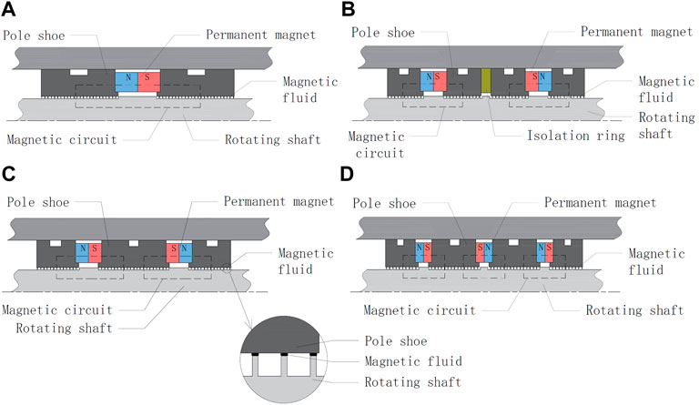
FIGURE 1. Structural design of vacuum magnetic fluid sealing device. (A) Single magnet multistage sealing structure. (B) Double magnets plus isolation ring multistage sealing structure. (C) Double magnets multistage sealing structure. (D) Three magnets multistage sealing structure.
The structure shown in Figure 1A is a single magnet multistage sealing structure with only one magnetic circuit, which is simple and easy to use. However, because of the pressure resistance requirement, there are many single-side pole teeth and large magnetic flux, which require the use of permanent magnets with large magnetic energy product, and their corresponding volume and weight will be larger, and the overall pressure resistance of the device will be reduced when the number of pole teeth is too many. The structure shown in Figure 1B is a multistage sealing structure with two magnets and an isolation ring, in which the two magnetic circuits exist independently and are separated by a nonconducting magnetic isolation ring. The outer diameter of the isolation ring is the same as the outer diameter of the pole shoes, but the precision of the sealing structure is high, and adding the isolation ring will increase the overall weight. The structure shown in Figure 1C is a double magnet multistage sealing structure, which is a deformation of the structure shown in Figure 1B. Instead of separating two independent magnetic circuits with an isolation ring, two permanent magnets are connected in series in the direction of homogeneous repulsion, thereby increasing the length of the intermediate section of the pole shoe and the number of corresponding pole teeth, making it common for two permanent magnets, reducing the occurrence of magnetic leakage, generating a strong magnetic field, and significantly increasing the overall pressure resistance of the device. However, because the permanent magnets are opposite to each other, it is necessary to use permanent magnet materials with good demagnetization resistance. The structure shown in Figure 1D is a three-magnet multistage sealing structure, in which three permanent magnets are connected in series in the direction of two and two homogeneous repulsions to form three independent magnetic circuits; however, this sealing structure is difficult to process, the installation accuracy is difficult to ensure, and the increase in permanent magnets will increase the overall weight.
Based on the above analysis, after considering the processing accuracy, installation difficulty, weight, and pressure resistance requirements, the double magnet multistage sealing structure shown in Figure 1C is selected, including the magnetic conductive rotating shaft, two permanent magnets, two end pole shoes, and one intermediate pole shoe.
The size of the pressure resistance of the magnetic fluid sealing device is affected by many factors, among which the size and material of the permanent magnet, the structure of the pole shoe, the shape and number of teeth of the pole teeth, and the size of the seal gap are its main influencing factors (Zou et al., 1994), which are also the focus of the sealing device design.
It is known that the pressure resistance of a magnetic fluid sealing device is related to the magnetic field distribution in the seal gap. The larger the parameters of remanent magnetism and coercivity of permanent magnet, the larger the magnetic field gradient in the seal gap and the larger the pressure resistance of the magnetic fluid sealing device. Among several common permanent magnet materials, Nd–Fe–B permanent magnet material has the best value in terms of remanence, coercivity, maximum magnetic energy product, etc. (Song and Chen, 1984); moreover, its hardness is high and the economy is good, so Nd–Fe–B is chosen as the permanent magnet material. The permanent magnet adopts an integral ring structure, which has little magnetic leakage and better magnetic stability. Through calculation, an inner diameter of 18 mm, an outer diameter of 30 mm, and a thickness of 8 mm were determined for a permanent magnet.
The pole shoe is an important part of the magnetic fluid sealing device (Xu et al., 2019), and the material chosen is 2Cr13, a soft magnetic material with excellent magnetic properties and good machinability. A groove is machined on the outside of the pole shoe, and a seal is used to ensure a static seal between the pole shoe and the nonconducting magnetic housing. Moreover, to facilitate the installation and positioning of the permanent magnet, a tab is machined on the side of the pole shoe that contacts the permanent magnet.
Because of the small shaft diameter of the spindle section of the device, the inner diameter of the corresponding pole shoe is also small. To facilitate processing and installation, the pole teeth are designed on the magnetic guide shaft. The shape and size of the pole teeth are very important for the pressure resistance of the magnetic fluid seal. Compared with the three common tooth shapes: triangular teeth, rectangular teeth, and trapezoidal teeth (Cheng, 2016), rectangular teeth are easier to process, performance can be easily guaranteed, and the magnetic force lines are more concentrated under the rectangular teeth. Thus, rectangular teeth are chosen for the pole tooth shape; the tooth shape parameters of rectangular teeth (Cheng, 2016) are
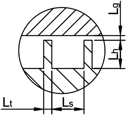
FIGURE 2. Pole tooth morphology.
In this article, the number of intermediate section pole teeth and the seal gap size of the magnetic fluid sealing device are changed accordingly. The magnetic field distribution under different structures is simulated and analyzed using the finite element method.
Because the vacuum magnetic fluid seal is an axisymmetric structure, the magnetic field of the permanent magnet does not change with time. To simplify the calculation, this article uses Ansys simulation software to perform a 2D static analysis and makes the following assumptions (Li, 2010; Li et al., 2002).
1) The permanent magnet is assumed to be magnetized uniformly, and its uniformity is not affected by the magnetic field.
2) The distribution of seal gaps in this sealing device is assumed to be uniform.
3) The magnetic fluid is assumed to have approximately the same magnetic permeability as the vacuum.
4) All errors generated during machining and assembly are ignored.
First, create the physical environment in Ansys simulation software, and define the material properties of the two permanent magnets, the three pole shoes, the rotating shaft, and the air as follows: the vacuum permeability of air
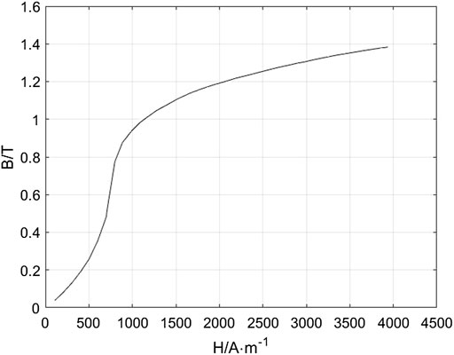
FIGURE 3. B–H curve of 2Cr13.
As an example, the number of pole teeth in each end is 13, the number of pole teeth in the intermediate section is 19, and the seal gap is
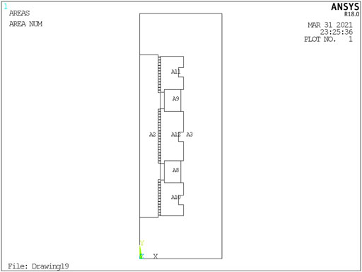
FIGURE 4. Import structure diagram.
Setting the smart grid division accuracy level to 5, triangle or quadrilateral grids are automatically generated on the plane by 2D free meshes. The grid accuracy can be controlled by the number of grids, edge lengths, and curvature in Ansys. It can be seen that the grid at the pole tooth is more dense, which is convenient for subsequent analysis of the magnetic field strength. After the mesh division, the boundary condition of parallel magnetic lines is selected to restrict the magnetic lines inside the boundary in order to prevent the magnetic leakage phenomenon. After dividing the grid and loading the boundary conditions, it is shown in Figure 5 shows the structure schematic.
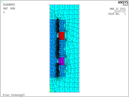
FIGURE 5. Delineate the grid and load the boundary conditions.
After the preprocessing is completed, the static analysis can be further solved. The simulation analysis results are converged, and the processing results can be viewed after the successful solution as shown in Figure 6 and Figure 7.
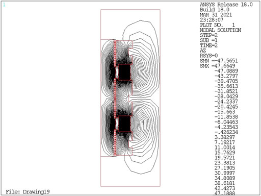
FIGURE 6. Magnetic line distribution map.
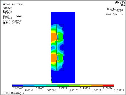
FIGURE 7. Node magnetic flux density cloud.
As shown in Figure 6, the magnetic lines of force are distributed. It can be seen that the magnetic lines of force start from the permanent magnet and return to the permanent magnet after passing through the pole shoe, magnetic fluid, and rotating shaft, forming two closed magnetic circuits. In the seal gap between the pole teeth and the pole shoe, the magnetic lines are the most dense, and only a small amount of magnetic lines are distributed in the air, which means the magnetic flux at the gap is the largest and the magnetic field distribution is more concentrated. At the same time, most of the magnetic lines of force pass through the pole teeth, which means that the pole teeth give full play to the role of accumulating magnetic lines of force and firmly adsorb the magnetic fluid at the seal gap, making the sealing device more reliable.
As shown in Figure 7, the nodal magnetic flux density clouds visually reflect the magnetic field strength of each part of the device. It can be seen that the magnetic flux density in the intermediate section of the pole teeth is higher than that on both sides because the pole teeth in the intermediate section are supplied by permanent magnets with opposite poles on the left and right sides. The pole teeth on both sides are supplied by a single permanent magnet, and the magnetic flux density is relatively small. The magnetic flux density is the highest in parts where the pole teeth are close to the pole shoe, indicating that the magnetic field is the strongest at the pole teeth, so the structure of the magnetic fluid seal is reasonably designed. The pressure resistance of the seal is verified by specific numerical calculations below.
The number of pole teeth directly affects the magnetic field gradient and magnetic flux in the gap of the vacuum magnetic fluid sealing device (Fan, 2019), which directly affects the effect of sealing pressure resistance. Therefore, the reasonable design of the number of teeth is of great significance to improve the pressure resistance of the magnetic fluid seal.
In this article, we fix the size and material of two permanent magnets, and the number of pole teeth on both ends is 13; we also discuss the influence of the number of pole teeth in the intermediate section on the pressure resistance. The number of pole teeth in the intermediate section is from 2 to 22 for simulation calculation, and the total difference in magnetic field strength of multistage teeth is obtained. The pressure resistance is calculated by substituting the data into Eq. 3.
The relationship between the pressure resistance and the number of pole teeth in the intermediate section is shown in Figure 8. It is not difficult to find that when the number of intermediate section pole teeth increases from 2 to 15 and from 16 to 19; the pressure resistance of the sealing device increases with the increase in the number of teeth. When the number of intermediate section pole teeth is 16, the pressure capacity decreases slightly. It may be because of the calculation error caused by simulation grid division, which has little effect on the overall trend. When the number of intermediate section pole teeth increases from 19 to 22, the pressure resistance of the sealing device decreases with the increase in the number of teeth. This is because the maximum magnetic energy product provided is certain when the size and number of permanent magnets are fixed. The magnetic fluid in the intermediate section reaches magnetic saturation, and the magnetic field line distributed to each pole tooth decreases. Then, the magnetic field strength difference under each pole tooth decreases, resulting in a decrease in the pressure resistance of the device.

FIGURE 8. Relationship between the number of intermediate section pole teeth and pressure resistance.
Therefore, it is beneficial to set more number of pole teeth within the allowed axial length to improve the pressure resistance of the vacuum magnetic fluid sealing device but not too many, generally not more than 20 pole teeth.
In the general magnetic fluid seal structure, the seal gap refers to the gap between the top of the pole tooth and the shaft or sleeve; for this vacuum magnetic fluid sealing device, the seal gap refers to the gap between the top of the pole tooth and the pole shoe. In general, the seal gap in the magnetic fluid seal structure of less than 0.25 mm means a small gap (Yang, 2014). Because of the small diameter of the shaft, the device is designed for small gaps. The number of pole teeth at both fixed ends is 13, and the number of pole teeth in the intermediate section is 19, which are taken as 0.1, 0.15, 0.2, and 0.25 mm for simulation calculation. The total difference of magnetic field strength of multistage pole teeth is obtained, which is substituted into Eq. 3 to calculate the pressure resistance, shown in Table 2.
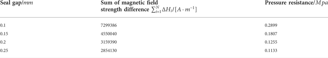
TABLE 2. Relationship between seal gap size and magnetic field strength and pressure resistance.
In Ansys simulation software, a number of key points are taken from the bottom up along the positive direction of y-axis at the seal gap. These points are connected to form a path through the seal gap, and the distribution of magnetic lines is mapped to this path to obtain the magnetic field intensity values and their distribution at the corresponding points in the seal gap. The simulation results of the magnetic field under different seal gaps are shown in Figure 9. It can be seen that the magnetic field strength is highest at the tip of the pole tooth and lowest at the groove on both sides of the pole tooth for the seal gap from 0.1 to 0.25 mm. At the same time, the difference in magnetic field strength between the tip and the groove decreases as the seal gap increases. The tip effect exists at the shoulder of the shaft, where many magnetic lines of force are gathered and the magnetic field strength is the highest. Because of the large number of pole teeth of the device, the magnetic lines of force gathered at the shoulder of the shaft do not have much influence on the final result, which further reflects the rationality of the seal structure design.
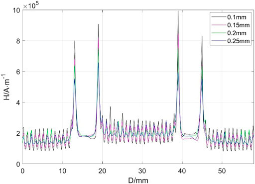
FIGURE 9. Magnetic field distribution under different seal gaps.
The relationship between the pressure resistance and the seal gap size is shown in Figure 10. The pressure resistance at a seal gap of 0.15 mm decreases by approximately one-third compared with that at a seal gap of 0.1 mm and decreases even more at a seal gap of 0.2 and 0.25 mm. This reflects that for small gap magnetic fluid sealing devices, the pressure resistance of magnetic fluid seal decreases with the increase in the seal gap, under the condition that other parameters remain unchanged.
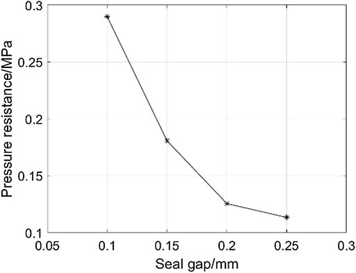
FIGURE 10. Relationship between seal gap size and pressure resistance.
In this article, a double magnet multistage magnetic fluid sealing device meeting the requirements of industrial applications is designed by analyzing the advantages and disadvantages of four different structures of vacuum magnetic fluid sealing devices under the condition of a fixed overall length of the sealing device. The proposed structure of the double magnet multistage magnetic fluid sealing device is optimized and determined by the design of key parts, simulation of the finite element of the magnetic field, and the calculation of sealing pressure resistance under different structural parameters. The proposed optimized structure is that the number of polar teeth at both ends is 13, the number of polar teeth in the intermediate section is 19, and the sealing clearance is 0.1 mm.
Compared with the traditional single magnet magnetic fluid sealing device, the advantages of the proposed device can be summarized as follows:
1) The processing difficulty of the three pole shoes and the installation difficulty of the whole device are both reduced by designing the pole teeth on the magnetic guide rotating shaft.
2) The overall withstand voltage capability of the device is greatly improved using two permanent magnets with the same pole and opposite pole to form two magnetic circuits.
Ansys simulation results show that the proposed structural design of the device is reliable and reasonable, and the theoretically calculated withstand voltage value can reach 0.2899 Mpa, which meets the working requirements. This article lays a foundation for the subsequent physical processing of vacuum devices and also provides a reference for the structural design and analysis of small-diameter low-speed vacuum magnetic fluid sealing devices.
The original contributions presented in the study are included in the article/supplementary materials; further inquiries can be directed to the corresponding author.
SL: Built the logic of the article, wrote the article, modeled the analysis, designed and produced the simulation, and summarized the data conclusions. DL: Inspected the article and evaluated the results. XH: Checked the article and guided the model simulation. ZZ: Analyzed the model building.
Supported by the National Natural Science Foundation of China (Grant Nos. 51735006, 51927810, and U1837206) and Beijing Municipal Natural Science Foundation of China (Grant No. 3182013).
The authors declare that the research was conducted in the absence of any commercial or financial relationships that could be construed as potential conflicts of interest.
All claims expressed in this article are solely those of the authors and do not necessarily represent those of their affiliated organizations or those of the publisher, the editors, and the reviewers. Any product that may be evaluated in this article or claim that may be made by its manufacturer is not guaranteed or endorsed by the publisher.
Berkovsky, B. M., Medvedev, V. F., and Krakov, M. S. (1993). Magnetic fluids engineering applications[M]. New York: Oxford University Press.
Chen, Yibiao, Li, Decai, Zhang, Yanjuan, Li, Z., and Zhou, H. (2020). The influence of the temperature rise on the sealing performance of the rotating magnetic fluid seal. IEEE Trans. Magn. 56 (11), 1–10. doi:10.1109/tmag.2020.3023018
Cheng, H. (2016). Research on magnetic fluid seal of reaction kettle device [D]. Beijing: Beijing Jiaotong University.
Cheng, Y. (2020). Theoretical and experimental study of heat transfer characteristics of magnetic fluids based on high-speed seals [D]. Beijing: Beijing Jiaotong University.
Chi, C. (2011). Physical fundamentals and applications of ferromagnetic fluids [M]. Beijing: Beijing University of Aeronautics and Astronautics Press, 6–12.
Fan, C. (2019). Numerical analysis and experimental verification of magnetic fluid seal for hydraulic cylinder of construction machinery[D]. Liuzhou: Guangxi University of Science and Technology.
Gu, H., Song, P., and Zhu, L. (2002). Experimental study on the performance of magnetic fluid seal[J]. Lubr. Seal. (03), 32–34.
He, X., Li, D., and Sun, M. (2008). Experimental study of magnetic fluid static seal for large diameter flanges[J]. J. Vac. Sci. Technol. 28 (2), 179–181.
He, X., Li, D., and Wang, H. (2014). Influence of gravity on performance of magnetic fluid seal [J]. J. Vac. Sci. Technol. 34 (11), 1160–1163.
Jain, K., Pant, R. P., and Pathak, S. (2017). Magnetic fluid based high precision temperature sensor[J]. IEEE sensors J. 17 (9), 2670–2675. doi:10.1109/JSEN.2017.2675440
Li, D., and Du, H. (2018). Research progress on key issues of magnetic fluid rotary seal[J]. J. Vac. Sci. Technol. 38 (7), 564–574.
Li, D., Hong, J., and Yang, Q. (2002). Study on magnetic fluid seal of dry Roots vacuum pump[J]. Vac. Sci. Technol. (473), 78–81.
Li, D., Wang, Z., and Yao, J. (2014). New magnetic fluid seal[J]. J. Beijing Jiaot. Univ. 38 (4), 1–6.
Lv, T., Wang, L., and Chen, Y. (2020). Finite element simulation analysis and research on magnetic field strength of magnetic fluid sealing device[J]. Mechanics 47 (10), 41–47.
Radionov, A. V. (2015). Application of magnetic fluid seals for improving reliability of air coolers. Chem. Pet. Eng. 51 (7-8), 481–486. doi:10.1007/s10556-015-0073-5
Song, H., and Chen, P. (1984). Permanent magnetic materials and their applications [M]. Beijing: Mechanical Industry Press.
Sun, M., Li, D., and He, X. (2007). Numerical analysis and optimal design of magnetic field for magnetic fluid seal[J]. J. Vac. Sci. Technol. (3), 269–272.
Szydło, Z., Zachara, B., and Ochoński, W. (1999). “Ferro-magnetic fluids and their application in machine building (in Polish),” Krynica: in 1st Conference on automation of machines, devices and processes.
Wang, H., Li, D., and He, X. (2016). Experimental study on the effect of rotational speed of rotating shaft on the pressure resistance of magnetic fluid-liquid dynamic seal[J]. J. Vac. Sci. Technol. 36 (08), 945–949.
Wang, H., Li, D., and Shaobo, Z. (2016). Comparative study of the failure pressure between sealing liquids and gas with magnetic fluid [J]. Food Mach. 32 (11), 68101–68170.
Wang, Z. (2019). Research on magnetic fluid sealing of liquid media [D]. Beijing: Beijing Jiaotong University.
Xu, H., Bao, J., and Yin, Y. (2019). Design and simulation of roller sealing and lubrication based on magnetic nanofluid[J]. Lubr. Seal. 44 (6), 109–112.
Yang, J., and Huang, W. (2017). A brief review on the progress of magnetic liquid lubrication technology[J]. Surf. Technol. 46 (6), 61–68.
Yang, X. (2014). Theoretical and experimental study of large gap stepped magnetic fluid rotary seal[D]. Beijing: Beijing Jiaotong University.
Keywords: magnetic fluid seal, structure design, finite element analysis, pressure resistance, vacuum device
Citation: Liu S, Li D, He X and Zhang Z (2022) Structure design study of vacuum magnetic fluid seal. Front. Mater. 9:932697. doi: 10.3389/fmats.2022.932697
Received: 30 April 2022; Accepted: 07 July 2022;
Published: 08 August 2022.
Edited by:
Yang Yu, Western Sydney University, AustraliaReviewed by:
Tadeusz Szumiata, Kazimierz Pułaski University of Technology and Humanities in Radom, PolandCopyright © 2022 Liu, Li, He and Zhang. This is an open-access article distributed under the terms of the Creative Commons Attribution License (CC BY). The use, distribution or reproduction in other forums is permitted, provided the original author(s) and the copyright owner(s) are credited and that the original publication in this journal is cited, in accordance with accepted academic practice. No use, distribution or reproduction is permitted which does not comply with these terms.
*Correspondence: Decai Li, bGlkZWNhaUBtYWlsLnRzaW5naHVhLmVkdS5jbg==
Disclaimer: All claims expressed in this article are solely those of the authors and do not necessarily represent those of their affiliated organizations, or those of the publisher, the editors and the reviewers. Any product that may be evaluated in this article or claim that may be made by its manufacturer is not guaranteed or endorsed by the publisher.
Research integrity at Frontiers
Learn more about the work of our research integrity team to safeguard the quality of each article we publish.