 Wenjuan Yu
 Decai Li
 Guobao Zang
 Deyi Wang
 Zhili Zhang
94% of researchers rate our articles as excellent or good
Learn more about the work of our research integrity team to safeguard the quality of each article we publish.
Find out more
ORIGINAL RESEARCH article
Front. Mater. , 25 July 2022
Sec. Smart Materials
Volume 9 - 2022 | https://doi.org/10.3389/fmats.2022.930124
This article is part of the Research Topic Characterization and Application of Magneto-sensitive Soft Materials View all 20 articles
Magnetic fluid seals have the advantages of zero leakage, long life, simple structure and high reliability, and have become one of the most widely used applications of magnetic fluids. In this paper, the effect of magnetic fluid evaporation on the pressure resistance of magnetic fluid seals is studied. In terms of theory, through theoretical calculation and simulation analysis, a calculation method for the pressure resistance of magnetic fluid seals is established. In terms of experiments, firstly, five groups of control groups were set up to conduct evaporation experiments under the same conditions, and magnetic fluids with different evaporation rates were obtained; Secondly, the performance of magnetic fluids with different evaporation rates was tested, and the flow curves, viscosity-temperature curves, and magnetic-viscosity curves of magnetic fluids were obtained respectively, and the effect of evaporation on the performance of magnetic fluids was analyzed; Finally, magnetic fluid sealing experiments with different evaporation rates were carried out. It is found that evaporation increases the pressure resistance of static seal to a certain extent, which is of great significance.
Magnetic fluid is a new type of nano-scale functional material, which is composed of magnetic particles, surfactant and base carrier liquid, which has both the magnetic properties of solid and the fluidity of liquid (Chi et al., 1993; Rosensweig, 2002; Li, 2003). Magnetic fluid seal is a new type of sealing method, which has the advantages of zero leakage, long life and high reliability (Chi et al., 1993; Chen et al., 2018; Yu et al., 2021). In the practical application of the magnetic fluid sealing device, the magnetic fluid exists in the gap between the pole teeth and the rotating shaft, forming several “O”-shaped sealing rings, which achieves the sealing effect (Chi, 2011; Li et al., 2021; Niu, 2021).
With the increasing application of magnetic fluid seals, the requirements for the pressure resistance performance of magnetic fluid seals are also getting higher and higher. In recent years, some scholars have carried out many studies on the factors affecting the pressure resistance of magnetic fluid seals. Zou et al. (2002) studied that centrifugal force will lead to the decline of the rotary sealing ability of magnetic fluids. He et al. (2019a) believed that under the condition of large diameter and large gap, gravity will seriously affect the pressure resistance performance of magnetic fluid seals. The results show that magnetic fluid seal has a limit size that is directly proportional to the magnetic field gradient in the sealing gap and is inversely proportional to the ratio of magnetic fluid density to the magnetization. When the diameter of magnetic fluid “O” rings is much smaller than the limit size, gravity has almost no effect. When approaching or even exceeding the limit size, gravity will cause the pressure resistance of the magnetic fluid seal to drop. Cheng et al. (2021) studied the effect of rheology on the sealing starting torque, and used perfluoropolyether-based magnetic fluids and diester-based magnetic fluids to conduct dynamic sealing experiments, and found that magnetic fluids with higher viscosity showed correspondingly higher starting torque. Saurabh et al. (Parmar et al., 2021) studied the influence of magnetic fluid volume, pole-piece thickness, radial clearance and particle volume fraction of a fluid on the pressure resistance of the seal combined with the finite element method, and obtained the optimum volume of a fluid is 10 mm3 for the optimum pole-piece thickness 3.5 mm and radial clearance 0.275 mm. Yuan et al. (Yuan et al., 2022) studied the magnetic fluid seal with large shaft diameter, and believed that the radial swing of the main shaft during the operation had a serious impact on the sealing performance. Therefore, an axial-radial series magnetic fluid sealing structure is designed to limit the swing displacement of the main shaft, thereby maintaining the overall pressure-resistant stability of the seal. Yang et al. (Yang and Li, 2016) designed a new type of stepped magnetic fluid seals in order to improve the pressure resistance of magnetic fluid large-gap seals. By comparing and analyzing the new seal and the traditional seal structure by experimental method, it is found that the divergent stepped magnetic fluid seal has better performance and is an effective method to improve the large gap magnetic fluid sealing ability. These studies have a certain effect on the pressure resistance of magnetic fluid seals, but there is little research on the effect of magnetic fluid evaporation on the seal pressure resistance. The relationship between the evaporation of the magnetic fluid in the sealing device and the sealing pressure value is not clear. Since the magnetic fluid is inside the sealing device, the evaporation rate of the magnetic fluid cannot be controlled. There are many difficulties in studying the effect of the evaporation of the magnetic fluid sealing.
In this paper, the magnetic fluid is evaporated separately to obtain samples with different evaporation rates, and then the rheological performance test and the sealing pressure test are carried out. Including the viscosity change of the magnetic fluid with different evaporation rates, the magnetic viscosity curve of the magnetic fluid, the flow performance of the magnetic fluid, etc. The analysis shows that the evaporation of the magnetic fluid makes the viscosity of the magnetic fluid increase and the fluidity worsens. For the rotary seal, the torque will increase, which is not conducive to the dynamic seal; but to a certain extent, the pressure resistance of the static seal will increase.
The main structure of the magnetic fluid seal is shown in the Figure 1. The magnetic fluid seal is mainly composed of a pole piece, a permanent magnet and a magnetic conductive shaft. There is a certain gap between the pole piece and the shaft, and the surface adjacent to the pole piece and the magnetic conducting shaft is provided with tooth slots to form several pole teeth. The permanent magnet provides a magnetic source, forms a magnetic circuit with the pole piece and the magnetic conducting shaft, and adsorbs the magnetic fluid at the pole teeth to form several liquid sealing rings. The sealing ring exists in the gap between the pole piece and the rotating shaft to achieve the purpose of sealing. Both static sealing and dynamic sealing can be achieved. Dynamic seals include rotary seals and reciprocating seals (He et al., 2019b; Chen, 2019; Matuszewski and Bela, 2021; Zhang et al., 2022).
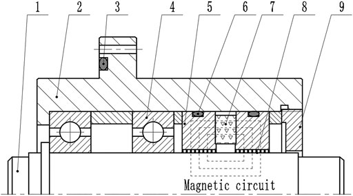
FIGURE 1. Main structure diagram of magnetic fluid seal. 1-rotation shaft, 2-shell, 3-sealing ring, 4-bearing, 5-pole shoe, 6-sealing ring, 7-permanent magnet, 8-magnetic fluid, 9-end cover.
According to the equation of motion of magnetic fluids (Wang, 2019; Zhang et al., 2019)
And
In the formula:
Suppose:
1) Magnetic fluid density is constant. Eq. 4 can be obtained from the continuous Equation 3 of fluid motion.
2) The flow is a vortex flow.
3) Magnetic fluid is intrinsic, and the change of external magnetic field does not cause the rotation of magnetic solid particles (Parmar et al., 2021). So we get
And
Change gravity to gradient form, h is the height of the analysis object to the reference point,
According to the identity transformation, the simultaneous Eqs 1–7, the general form of the Bernoulli equation for magnetic fluids is obtained as,
When the magnetic fluid is in steady isothermal flow, Eq. 8 can be simplified as
By the general expression of boundary conditions (Li, 2010)
In the formula: the subscripts “1” and “2” represent the two sides of the interface, “1” represents the magnetic fluid side, “2” represents the sealed medium side;
The formula for calculating the surface tension pc of the contact surface is
In the formula:
Suppose:1) consider that the magnetic field lines coincide with the isomagnetic field lines; 2) ignore the gravity and surface tension of the magnetic fluid itself.
Applying Bernoulli’s equation to the boundary surface, we have
Combined with the boundary condition (13), we get
Substitute Eq. 15 into Eq. 14 to get
Equation 16 is the formula for calculating the pressure difference between the two sides of the magnetic fluid at a single pole tooth. When the magnetic field strength in the sealing gap of the magnetic fluid is very high and the magnetic fluid is in the state of saturation magnetization, the Formula (16) can be simplified as
In the formula,
Figure 2 shows the main structural of the magnetic fluid sealing device used in the sealing experiment. Different from the traditional structure, this sealing structure has three pole pieces in total. The pole piece is cylindrical as a whole, with an inner diameter of 30.2 mm and an outer diameter of 50 mm. Each pole piece is connected by a thin wall with a thickness of 1 mm. The integrated pole shoe structure has the advantages of easy disassembly and assembly, low processing precision requirements, and the pole teeth are not easily damaged. The permanent magnet is installed at the thin wall, and the two permanent magnets are cylindrical magnets. The circular plane is the polar surface, the diameter of which is 6 mm and the thickness is 5 mm. The two polar surfaces of the magnet correspond to the side walls of the pole shoe. The polarity arrangement is N-S for S-N, or S-N for N-S. The permanent magnets are installed at the thin wall, and the cylindrical magnets used in the two permanent magnets have the polarity arrangement of N-S corresponding to S-N, or S-N corresponding to N-S. Bearings use deep groove ball bearing 61,906. The diameter of the rotating shaft is 30mm, the unilateral gap with the inner ring of the pole shoe is 0.1mm, and the material of the rotating shaft and the pole shoe is 2Cr13. The material of the shaft and pole piece is 2Cr13. In this experiment, only the four pole teeth of this sealing structure are used, and the position shown in Figure 2 is the four pole teeth at the left first-level pole piece. During the installation process, the pole pieces and shell are installed last. After the magnetic fluid is injected into the four pole teeth of the left pole piece, the pole piece is installed from left to right into the shell equipped with the rotating shaft, so that the magnetic fluid can be guaranteed to be all at the left pole piece.
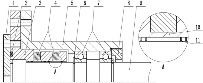
FIGURE 2. Magnetic fluid sealing device. 1-upper end cover, 2-sealing ring, 3-integrated pole shoe, 4-shell, 5-permanent magnet, 6-circlip, 7-bearing, 8-lower end cover, 9-rotation shaft,10-thin wall, 11-magnetic fluid.
ANSYS software is used to simulate the static magnetic fluid seal. The magnetic field distribution at the sealing gap in the magnetic fluid sealing structure can be obtained, and then the theoretical withstand pressures value can be calculated. Assumptions: 1) The permanent magnet is a ring-shaped magnet, and the magnetization is uniform; 2) The magnetic permeability of the magnetic fluid is the same as that of the air.
The material settings of each part: the permeability of the air domain is set to one; the permanent magnet is a NdFeB magnet with a grade of N38, its permeability is set to 1.138, and the coercive forces on both sides are set to 1.089 × 10⁶A/m and -1.089 × 10⁶A/m; the pole piece and the shaft are defined as 2Cr13 material, and the BH curve of the 2Cr13 material is shown in Figure 3.
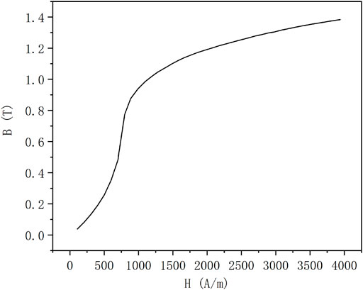
FIGURE 3. 2Cr13 material B-H curve.
Through the intelligent size control technology in ANSYS, use the SMARTSIZE command to divide the mesh and subdivide it to 0.1 for mesh division processing. Next, define the boundary condition, that is, the infinite magnetic field is parallel to the model boundary. Finally, the magnetic field is solved for the model, and the completion mark is iterative convergence. The distribution of magnetic field lines is shown in Figure 4, and it can be seen that most of the magnetic field lines pass through the pole teeth.
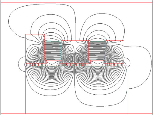
FIGURE 4. Magnetic line distribution.
Select a path at the sealing gap, the radial distance from the rotating shaft is 0.01mm, and parallel to the rotating shaft. Since only the four pole teeth of the sealing device are used in the experiment in this paper, only the magnetic induction intensity value at the four pole teeth is obtained, The starting point 1 and the ending point 2 of the path are shown in Figure 5. The magnetic induction intensity distribution at the path is obtained as shown in Figure 6.
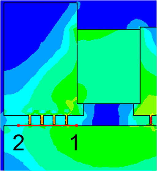
FIGURE 5. Path selection diagram.
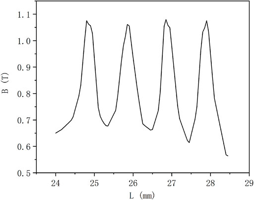
FIGURE 6. Magnetic induction strength distribution.
It can be seen from Figure 6 that the magnetic field intensity reaches the maximum value at the middle of the pole teeth, and the magnetic field intensity is the minimum at the middle part of the two pole teeth. Through calculation, the sum of the difference between the maximum magnetic induction intensity and the minimum magnetic induction intensity at the pole teeth is 1.95T, and then the theoretical withstand pressure value can be calculated.
Due to the particularity of the magnetic fluid seal, the evaporation of the magnetic fluid cannot be directly judged from the outside of the sealing device. In order to quantitatively study the effect of different evaporation rates on the pressure resistance of magnetic fluid seals, the experiment is divided into two parts. One is the magnetic fluid evaporation experiment, and the magnetic fluid samples with different evaporation rates are obtained; The second is the pressure test of magnetic fluid sealing, and the pressure test is carried out on magnetic fluid samples with different evaporation rates respectively.
This paper uses kerosene-based magnetic fluid to conduct evaporation experiments, where the size of the magnetic particles is 10 nm. (Yu et al., 2022). The kerosene-based magnetic fluid was injected into four identical flat-bottomed test tubes in equal amounts, and an evaporation experiment in the same environment was carried out in a high and low temperature test chamber as shown in Figure 7. Four kinds of kerosene-based magnetic fluids with different evaporation rates were obtained, which were 0, 3, 6, 9, and 11%, respectively. The calculation formula of the evaporation rate E in this paper is, E = m/m0, where m is the mass of the magnetic fluid evaporated, and m0 is the mass of the initial magnetic fluid.
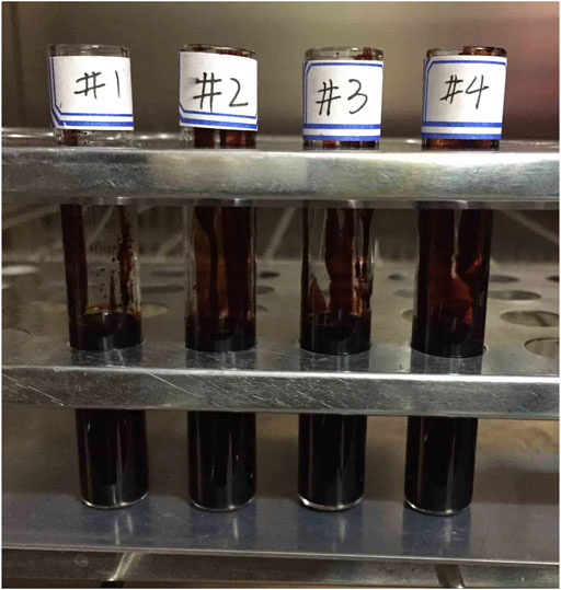
FIGURE 7. Kerosene-based magnetic fluid evaporation control group.
A magnetic fluid static sealing experimental platform is built, and the schematic diagram of the experimental device is shown in Figure 8. The air compressor is connected with the pressure reducing valve through the pressure transmission pipe, and the other side is connected with the throttle valve, which is used to control the gas flow rate, and then connected with the pressure inlet of the sealing device. A pressure sensor is connected to the pressure inlet of the sealing device, which is transmitted to a computer through a paperless recorder to record data. Among them, the paperless recorder is produced by Hangzhou Meikong Automation Technology Co., Ltd., and the model is MIK-R200T. The pressure sensor has a range of 1 MPa and an accuracy of 0.25%. By adjusting the pressure reducing valve and the throttle valve, the gas slowly enters the seal, the pressure in the seal will change, and the pressure change is recorded by the pressure sensor, and the actual pressure resistance value of the seal can be obtained.
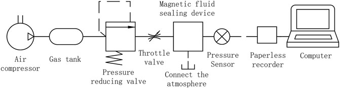
FIGURE 8. Static sealing experimental device schematic.
The static sealing pressure test was carried out on kerosene-based magnetic fluids with different evaporation rates. It is known that when the magnetic fluid evaporates in the sealing device, the quality of the magnetic fluid in the sealing gap will decrease. In order to approximate the simulation, the filling mass of the samples with different evaporation rates b is
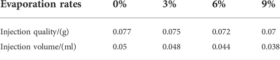
TABLE 1. Injection amount of kerosene-based magnetic fluid with different evaporation rates.
The magnetization curve of the magnetic fluid was measured using a vibrating sample magnetometer. The rheological curves of the magnetic fluids were all measured with Anton Paar’s MCR302 magnetorheological instrument. The temperature of the test was constant temperature of 20°C, and 0.1 ml of the magnetic fluid sample was taken and injected into the magnetorheology between the rotor and the stator of the magnetorheological instrument. In the gap, the shear motion inside the magnetic fluid is formed by the relative motion of the rotor and stator surfaces. Through the evaporation experiment, it is found that when the evaporation rate of the kerosene-based magnetic fluid reaches 11%, there is almost no fluidity, and the magnetic fluid cannot be uniformly injected into the sealing structure for the sealing pressure test, which is not for reference. Therefore, only four kinds of kerosene-based magnetic fluids with evaporation rate of 0, 3, 6 and 9% are respectively characterized.
Figure 9 shows the magnetization curves of the evaporation rates of 0, 3, 6 and 9%. It can be seen that the saturation magnetization of the magnetic fluid increases with the increase of the evaporation rate. This is because a large amount of the base carrier liquid evaporates during the evaporation process, and the volume fraction of the magnetic particles in the magnetic fluid increases, resulting in an increase in the magnetization. The density and saturation magnetization of magnetic fluids with different evaporation rates are shown in Table 2.
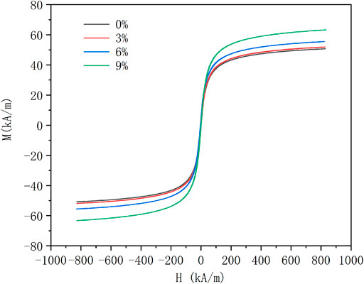
FIGURE 9. Magnetization curves of magnetic fluids with different evaporation rates.
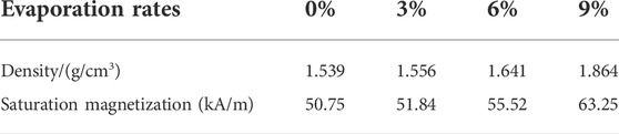
TABLE 2. Different evaporation rate magnetic fluid density and saturation magnetization intensity.
As shown in Figures 10A,B, the magneto-viscosity curves with evaporation rates of 0 and 9% are respectively set with five shear rates (25s−1, 50s−1, 75s−1, 100s−1) control group. It can be seen from Figure 10A that the viscosity of the magnetic fluid with the evaporation rate of 0% increases with the increase of the magnetic field strength and finally tends to be flat, and has little relationship with the shear rate. It can be seen from Figure 10B that the viscosity of the kerosene-based magnetic fluid with an evaporation rate of 9% first increases with the increase of the magnetic field strength. When the magnetic field exceeds a certain value, the viscosity of the magnetic fluid decreases. This is most pronounced at lower shear rates.
FIGURE 10. Magnetic viscosity curves of kerosene-based magnetic fluids with different evaporation rates. (A) is the magnetic viscosity curve when the evaporation rate is 0%. (B) is the magnetic viscosity curve when the evaporation rate is 9%.
Figure 11 shows the comparison of the magnetic viscosity curves of kerosene-based magnetic fluids with evaporation rates of 0, 6 and 9% when the shear rate is 100 s−1. It is not difficult to see that the viscosity of the magnetic fluid with a larger evaporation rate is larger. In the absence of a magnetic field, the viscosity of the kerosene-based magnetic fluid with an evaporation rate of 0% is 118.91 mPa s, the viscosity of the kerosene-based magnetic fluid with an evaporation rate of 6% is 564.62 mPa s, and the viscosity of kerosene-based magnetic fluid with an evaporation rate of 9% is as high as 3387.4 mPa s. Evaporation has a great influence on the viscosity of the magnetic fluid, and also has an effect on the magnetic viscosity characteristics of the magnetic fluid.
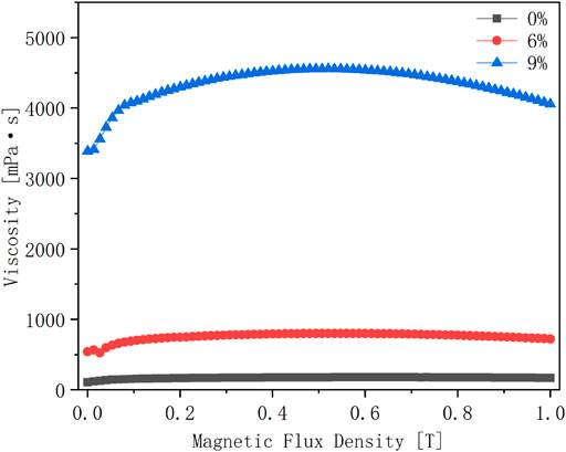
FIGURE 11. Magnetic-viscosity curves of kerosene-based magnetic fluids with different evaporation rates at a shear rate of 100 S−1.
In addition, taking the shear rate as the independent variable and the viscosity as the dependent variable, the change curves of the viscosity of the kerosene-based magnetic fluid with the shear rate of the evaporation rate of 0, 3, 6 and 9% were obtained. As shown in Figures 12A,B, the results are obtained under the condition that the magnetic field strength is 0 and 0.2 T, respectively. Under the condition of no magnetic field, it can be seen that when the evaporation rate is less than 6%, with the increase of shear rate, the viscosity of the magnetic fluid remains basically constant, and the phenomenon of shear thinning is not obvious, but for a magnetic fluid with an evaporation rate of 9%, when the shear rate is close to 100 s−1, it is clear that the viscosity decreases with increasing shear rate. It can be obtained that the greater the evaporation rate of the magnetic fluid, the more obvious the shear thinning phenomenon will be. When the magnetic field strength is 0.2 T, the viscosity of the magnetic fluid with the evaporation rate of 0% remains stable regardless of the shear rate. For the evaporated magnetic fluid, the viscosity decreases with the increase of the shear rate. The greater the evaporation rate, the more obvious the decrease in viscosity with the increase of the shear rate. It can be obtained that in the presence of a magnetic field, the evaporation of the magnetic fluid has a great influence on the viscosity.

FIGURE 12. Variation of viscosity with shear rate for kerosene-based magnetic fluids with different evaporation rates under different magnetic field strengths. (A) is the magnetic field strength at 0T; (B) is the magnetic field strength at 0.2T.
Figures 13A,B show the relationship between shear stress and shear rate of four different evaporation rates (0, 3, 6, and 9%) of kerosene-based magnetic fluids under the conditions of magnetic field strength of 0 and 0.2T, respectively. It can be seen that the trends of the four different evaporation rates of kerosene-based magnetic fluids are consistent with or without a magnetic field. When the shear rate is less than 100 s−1, the shear stress does not change significantly with the shear rate. When the shear rate increases to a certain value, the shear stress increases with the increase of the shear rate, and this trend is most obvious in the kerosene-based magnetic fluid with the larger evaporation rate. As shown in Figure 13A, when the shear rate is 1000 s−1, the shear stress of 0% evaporation rate is 100.2 Pa, the shear stress of 3% evaporation rate is 131.8 Pa, and the evaporation rate of 6% is 131.8 Pa. The shear stress reaches 412.4 Pa, and the shear stress with an evaporation rate of 9% is as high as 1820.5 Pa, which is 18 times that of the unevaporated magnetic fluid. This results in increased starting torque for magnetic fluid rotary seals.
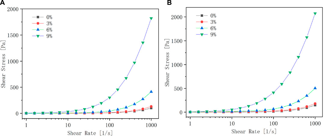
FIGURE 13. Flow curves of kerosene-based magnetic fluids with different evaporation rates under different magnetic field strengths. (A) is when the magnetic field strength is 0T; (B) is when the magnetic field strength is 0.2T.
Through the calculation of the above pressure resistance formula, combined with the maximum magnetic induction intensity difference at the pole teeth obtained by simulation analysis, and the saturation magnetization value, the theoretical pressure resistance value of kerosene-based magnetic fluid with different evaporation rates can be obtained, and the actual pressure resistance can be obtained through experiments. The comparison between the theoretical withstand pressure value and the actual withstand pressure value is shown in Figure 14.
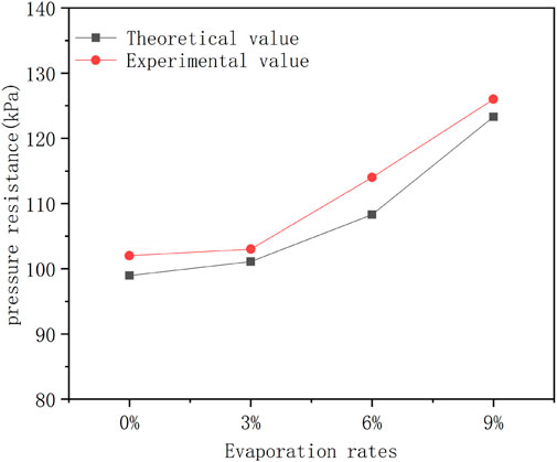
FIGURE 14. Different evaporation rate kerosene magnetic fluid withstand pressure.
It can be obtained that the actual withstand pressure value of all samples is larger than the theoretical withstand pressure value. This is because during the experiment, the magnetic fluid is blown to the next pole piece to form a new sealing ring, which increases a certain pressure resistance capacity, so the actual pressure resistance will be larger than the theoretical pressure resistance. In addition, it is not difficult to see that with the increase of the evaporation rate of the magnetic fluid, the pressure resistance value of the seal also increases.
According to the above analysis, although evaporation will reduce the magnetic fluid in the sealing gap, it will also increase the saturation magnetization of the magnetic fluid. According to the magnetic fluid sealing theory, it can be known that the sealing pressure value will increase accordingly, and the experiment also proves the correctness of the theory.
1) By characterizing the magnetization properties of magnetic fluids with different evaporation rates, it is obtained that the magnetic fluids with higher evaporation rates have higher saturation magnetization. To a certain extent, the pressure resistance value of the magnetic fluid seal is increased.
2) Characterize the rheological properties of magnetic fluids with different evaporation rates, including the flow curves and magnetic viscosity curves of kerosene-based magnetic fluids with different evaporation rates. The analysis shows that evaporation has a great influence on viscosity. The greater the evaporation rate, the greater the viscosity and the worse the fluidity. This will increase the starting torque of the magnetic fluid rotary seal.
3) Through the static sealing experiment of magnetic fluid with different evaporation rates, the experimental withstand pressure value is larger than the theoretical withstand pressure value, because in the withstand pressure experiment, the magnetic fluid is blown to the next stage pole piece, which increases the number of sealing rings, the withstand pressure increases accordingly. Although evaporation will reduce the magnetic fluid at the sealing gap, the experimental results show that the withstand pressure will increase, which proves the correctness of the theory and the feasibility of simulation.
The original contributions presented in the study are included in the article/supplementary material, further inquiries can be directed to the corresponding authors.
DL was in charge of the whole trial; WY wrote the manuscript and did laboratory analyses; GZ, DW, and ZZ contributed to the revision of the manuscript.
Supported by National Natural Science Foundation of China (Grant Nos. 51735006, 51927810, U1837206), and Beijing Municipal Natural Science Foundation of China (Grant No. 3182013).
The authors declare that the research was conducted in the absence of any commercial or financial relationships that could be construed as a potential conflict of interest.
All claims expressed in this article are solely those of the authors and do not necessarily represent those of their affiliated organizations, or those of the publisher, the editors and the reviewers. Any product that may be evaluated in this article, or claim that may be made by its manufacturer, is not guaranteed or endorsed by the publisher.
Chen, J. W., Li, D. C., and Hao, D. (2018). Investigation on the influence of temperature on starting torque of magnetic fluid seal. J. Magnetics 23, 436–441. doi:10.4283/jmag.2018.23.3.436
Chen, Y. B. (2019). Research on magnetic fluid sealing under high speed. [Beijing]: University of Science and Technology Beijing. (in Chinese).
Cheng, Y. H., Li, D. C., and Li, Z. K. (2021). Influence of rheological properties on the starting torque of magnetic fluid seal. IEEE Trans. Magn. 57, 1–8. doi:10.1109/tmag.2019.2934716
Chi, C. Q. (2011). Physics basis and application of ferrofluid. Beijing: Beihang University Press. (in Chinese).
Chi, C. Q., Wang, Z. S., and Zhao, P. Z. (1993). Ferrohydrodynamics. Beijing: Beihang University Press. (inChinese).
He, X. Z., Miao, Y. B., Wang, L., and Li, D. C. (2019). A brief description of the progress of magnetic fluid sealing liquid technology. J. Vac. Sci. Technol. 39, 361–366. (in Chinese).
He, X. Z., Wang, L., Yu, J., and Li, D. C. (2019). Influence of gravity on the anti-pressure ability of magnetic fluid seal. Int. J. Appl. Electromagn. Mech. 60, 21–32. doi:10.3233/jae-180054
Li, D. C. (2010). Theory and application of magnetic fluid seal. Beijing: Science Press. (in chinese).
Li, Z. X., Li, S. X., Wang, X., and Li, D. (2021). Numerical simulation and experimental study on magnetorheological fluid seals with flexible pole pieces. IEEE Trans. Magn. 57, 1–7. doi:10.1109/tmag.2021.3094868
Matuszewski, L., and Bela, P. (2021). New designs of magnetic fluid seals for reciprocating motion. Pol. Marit. Res. 28, 151–159. doi:10.2478/pomr-2021-0057
Niu, S. F. (2021). Theoretical and experimental research on key issues of magnetic fluid seal for electro-optical pod. [Beijing]: Beijing Jiaotong University. (in chinese).
Parmar, S., Upadhyay, R. V., and Parekh, K. (2021). Optimization of design parameters affecting the performance of a magnetic fluid rotary seal. Arab. J. Sci. Eng. 46, 2343–2348. doi:10.1007/s13369-020-05094-1
Wang, Z. Z. (2019). Research on magnetic fluid sealing liquid medium. [Beijing]: Beijing Jiaotong University. (in Chinese).
Yang, X. L., and Li, D. C. (2016). Experimental investigation of diverging stepped magnetic fluid seals with large sealing gap. Int. J. Appl. Electromagn. Mech. 50, 407–415. doi:10.3233/jae-150117
Yu, W. J., Li, D. C., Li, Y. W., Zhang, Z. L., and Dong, J. H. (2021). Design of small magnetic fluid seal for vacuum coating machine. J. Beijing Jiaot. Univ. 45, 124–129. (inChinese). doi:10.11860/j.issn.1673-0291.20210025
Yu, W., Li, D., and Niu, S. (2022). An experimental validation study on ferrofluid evaporation. Chin. J. Mech. Eng. 35, 50. doi:10.1186/s10033-022-00721-4
Yuan, F., Wang, S. Q., Li, D. C., Chen, D., Di, N. N., and Li, W. Y. (2022). Theoretical research on new structure and pressure resistance performance of magnetic fluid seals. Chin. J. Mech. Eng. 58, 213–220. (in Chinese).
Zhang, T., Li, D. C., and Li, Y. W. (2022). Structural design and optimization of combined seal of magnetic fluid seal and labyrinth seal. Chin. J. Mech. Eng., 1–10.
Zhang, Y. J., Chen, Y. B., Li, D. C., Yang, Z., and Yang, Y. (2019). Experimental validation and numerical simulation of static pressure in multi-stage ferrofluid seals. IEEE Trans. Magn. 55, 1–8. doi:10.1109/tmag.2017.2744606
Keywords: magnetic fluid, evaporation, seal, finite element, pressure resistant
Citation: Yu W, Li D, Zang G, Wang D and Zhang Z (2022) Influence of magnetic fluid evaporation on pressure resistance of magnetic fluid seal. Front. Mater. 9:930124. doi: 10.3389/fmats.2022.930124
Received: 27 April 2022; Accepted: 05 July 2022;
Published: 25 July 2022.
Edited by:
Tongfei Tian, University of the Sunshine Coast, AustraliaReviewed by:
Xufeng Dong, Dalian University of Technology, ChinaCopyright © 2022 Yu, Li, Zang, Wang and Zhang. This is an open-access article distributed under the terms of the Creative Commons Attribution License (CC BY). The use, distribution or reproduction in other forums is permitted, provided the original author(s) and the copyright owner(s) are credited and that the original publication in this journal is cited, in accordance with accepted academic practice. No use, distribution or reproduction is permitted which does not comply with these terms.
*Correspondence: Decai Li, bGlkZWNhaUBtYWlsLnRzaW5naHVhLmVkdS5jbg==
Disclaimer: All claims expressed in this article are solely those of the authors and do not necessarily represent those of their affiliated organizations, or those of the publisher, the editors and the reviewers. Any product that may be evaluated in this article or claim that may be made by its manufacturer is not guaranteed or endorsed by the publisher.
Research integrity at Frontiers
Learn more about the work of our research integrity team to safeguard the quality of each article we publish.