 Yikai Zhu†
 Mengchao Ma
- School of Instrument Science and Opto-electronics Engineering, Hefei University of Technology, Hefei, China
As a kind of sustainable energy source, ocean wave energy has always attracted attention. Because of the characteristics of multi-directions and low-bandwidth, the harvesting of wave energy has always been difficult. To harvest broadband wave energy in multiple directions and improve power generation efficiency, we present a multi-modal energy harvesting device by using a cross beam structure. In this device, the efficient harvesting of multi-frequency vibration energy in multiple directions has been achieved by using the multi-modal characteristics of the structure and the high power generation efficiency of the electric device based on liquid metal. Contrast experiments in multiple directions show that the device not only has the capability of multi-directional energy harvesting but also can work in the sweep range of the full band. Under horizontal excitation, compared with traditional single cantilever structure, the peak power density increased to 2227% and the working frequency band increased to 6.25 times. The experimental results show that the device significantly improves the efficiency of low-bandwidth multi-directional energy harvesting, providing a new method for vibration energy harvesting.
Introduction
Wave energy, the widely distributed vibration energy in nature, has always attracted attention (Hu et al., 2013). But the low frequency, broadband, and multi-directionality of wave energy result in its difficult harvesting, limiting the development and utilization of wave energy. There are many low-frequency, broadband, or multi-directional vibration energy harvesting technologies, but few can meet these three characteristics at the same time. Just like the linear vibration energy harvesters (Erturk and Inman, 2008, 2009) can be applied to low-frequency vibration energy harvesting, they usually only work near their resonance point, which results in the narrow frequency band of this type of vibration energy harvesters. Obviously it is a huge challenge to harvest wave energy.
There are two methods to broaden the frequency band of vibration energy harvester. The one is adding external force to the vibration energy harvester, enabling the vibrating structure to generate nonlinear multi-stable vibration (Harne and Wang, 2013; Pellegrini et al., 2013; Deng et al., 2019). Under weak external excitation, the introduction of external force will make the harvester fall into a single potential well and vibrate slightly, which will greatly reduce energy collection efficiency. The other method is designing the vibration energy harvester with a multi-modal vibration structure (Tadesse et al., 2009; Friswell et al., 2012; Ibrahim and Ali, 2012), making the vibration structure has multiple resonance frequencies in the low-frequency range, then broadening the frequency band of the harvester. A vibration-based multi-modal hybrid piezoelectric-electromagnetic energy harvester (Toyabur et al., 2018) has four resonant frequencies in the low-frequency range (below 25 Hz), and the working bandwidth reaches about 10 Hz. But the harvesters above are only sensitive to perpendicular excitations. As for excitations in other directions, they even don’t work. For multi-directional vibration like ocean waves (Wu et al., 2015; Zhang et al., 2016; Chen et al., 2018), it affects power generation efficiency. Therefore, in addition to broaden the working frequency (Arrieta et al., 2010; Kim I.-H. et al., 2011; Zhou et al., 2013, 2014), it is necessary to adapt to the multi-directional characteristics of wave energy (Xu and Tang, 2015; Zhao et al., 2015; Wu et al., 2018).
There are two ways to make the device harvest energy in multiple directions. The one is to place multiple independent vibrating structures in different directions (Andò et al., 2012). When the device is excited in a specific direction, the vibrating structure perpendicular to the direction will vibrates, but the structure utilization rate in this method is not high enough. The other way is adding coupling relationships to the vibrating structures in different directions (Xu and Tang, 2015, 2017). When the device is excited in a specific direction, not only does the vibrating structure perpendicular to the direction vibrates, but the vibrating structures in other directions also vibrate through the coupling relationship (Wang et al., 2016). This method has a high structural utilization rate. Meanwhile, because the mutual influence among vibration mechanisms, if the design is reasonable enough (Vibration mechanisms have different resonance frequencies), the energy harvester is able to have multiple modes, owning a wide frequency band. So the method of adding coupling relationships to the vibrating structures in different directions not only realizes multi-directional vibration energy harvesting, but also has the potential to harvest broadband wave energy.
The method of adding coupling relations can harvest low-frequency wave energy. When designing vibration mechanisms with different frequencies, the energy harvester can be able to harvest low-frequency wave energy by making one of the vibration mechanisms have a low resonance frequency. In addition to structural design, the choice of power generation materials also affects the harvesting of wave energy. Based on the triboelectric effect and the electric induction effect, a liquid-metal-based TENG is proposed, the power density and the energy conversion efficiency of this way can reach 133 kW/m3 and 70.6% (Fan et al., 2012a; Fan et al., 2012b; Yang et al., 2012; Tang et al., 2015). Compared to common piezoelectric and electromagnetic energy harvesting technologies (Sodano et al., 2004; Kim H. S. et al., 2011; Li et al., 2014; Toprak and Tigli, 2014), TENG can significantly improve the output power density and power generation efficiency of the device in the low-frequency range (Fan et al., 2012; Wang, 2013; Zhang et al., 2014; Wang, 2017). In addition, with fluidity, liquid metal is suitable for low-frequency, multi-directional, and broadband vibration energy harvesting (Tang et al., 2015; Zhang et al., 2017; Wang et al., 2018; Yang et al., 2018). Until now, there is no vibration energy harvester combined with liquid-metal-based TENG, which can simultaneously harvest low frequency, broadband, and multi-directional wave energy. Based on these, we propose to present a multi-modal energy harvesting device using a cross beam to achieve low frequency, broadband, multi-directional wave energy harvesting.
The multi-modal energy harvesting device broadens the working frequency band of the device through the multi-modal characteristics of the cross beam structure. The multi-directional harvesting capability of the cross beam combines with the fluidity of the liquid metal realizes multi-directional energy harvesting and broadens the working frequency range in the low-frequency range. Experiments show that the device not only can harvest multi-directional vibration energy in wide working frequency bands but also has good power generation efficiency and power density. The lighting comparing in the low-frequency range and lighting under wave more intuitively reflects the broadband characteristics of the device and proves its potential to harvest ocean wave energy.
Design and Mechanism
Figure 1 shows the overall structure of the multi-modal device, which consists of a cross beam and three triboelectric devices. The cross beam is a vertical cantilever beam connecting two branches in the middle position. Three triboelectric devices are respectively fixed on the tips of the two branches and the tip of the vertical cantilever to replace the traditional counterweight design and improve energy efficiency without increasing structural complexity.

FIGURE 1. Overall structure of the multi-modal device.
In order to intuitively investigate the modal characteristics of the device, we use software to simulate the natural frequencies and modal shapes of the device. Based on the fact that the energy collected by this device mainly comes from waves with frequencies below 5 Hz, 65 Mn steel was chosen as the material for this device. Since the one class resonant frequency of the cross beam structure with 0.7 mm thickness is at 2.79 Hz, which is close to 5 Hz, the selection of 0.7 mm thickness can collect wave energy better. The installation height of the branch beam on the vertical cantilever beam affects the resonant frequency of the cross beam structure. In the simulation experiment, the height is set to vary from 75 to 100 mm, and it is found that the performance best meets the working frequency requirement when the installation height is 86 mm, so 86 mm is chosen as the installation height, and the fixed restraint is added at the upper end of the vertical cantilever beam connection, and the lower part moves freely with the applied frequency. Since the liquid metal used in the device is mercury, which is denser and more complicated to set up as a flowing body for simulation, the liquid metal is approximated as a fixed structure in the simulation experiment. As shown in Figure 2, in the low-frequency range below 22 Hz, a total of five natural frequencies appear and correspond to the five vibration modes (a), (b), (c), (d), and (e), respectively. At the first-order natural frequency of 2.8 Hz, the structural deformation of the device is mainly the bending deformation of the vertical cantilever beam in the horizontal direction, which causes the three triboelectric devices to vibrate. 5.7 Hz is the second-order natural frequency and structural deformation is mainly caused by the torsional deformation of the vertical cantilever beam. At the third-order natural frequency of 8.4 Hz, the structural deformation is not only the bending deformation of the vertical cantilever beam in the horizontal direction, but also the bending deformation of the two branches in the vertical direction, the deformation in both directions is compounded. At the fourth-order natural frequency of 14.1 Hz, structural deformation is mainly the bending deformation of the two branches in the vertical direction, which drives the triboelectric device at the ends of the two branches to vibrate. The last-order natural frequency is 20.2 Hz and the structural deformation in this state mainly comes from the vertical cantilever beam. However, it is different from bending deformation at the first-order natural frequency. Instead, structural deformation occurs at the connection between the vertical cantilever beam and the two branches, causing the two branches move left and right in the horizontal direction. These five vibration modes have multi-directional vibration characteristics, which means that the device can drive the triboelectric device at the end of beams to vibrate under multiple directions and broadband external excitation, thus generating electric energy.
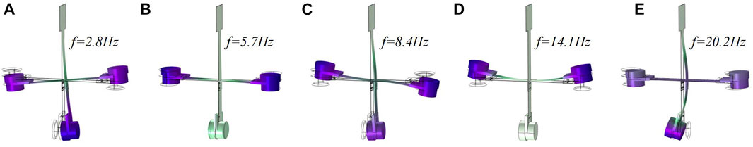
FIGURE 2. Natural frequencies and modal shapes of the device. (A) The first-order natural frequency; (B) The second-order natural frequency; (C) The third-order natural frequency; (D) The fourth-order natural frequency; (E) The last-order natural frequency.
As shown in Figure 3A, the triboelectric device based on the liquid metal (mercury, gallium or EGAIN) consists of a aluminum alloy threaded container, a aluminum alloy thread cap, a suitable amount of the liquid metal, a 3D printed material sleeve, two silicone seal rings and two triboelectric components (Kapton and copper conductor), the thickness of both copper and Kapton is 0.1 mm. In order to prevent the huge impact of the liquid metal leakage on the power generation capacity, we place two seal rings on the upper and lower surfaces and put the triboelectric components on both sides of the sleeve. The sealing ring and the sleeve are clamped with threads to make the liquid metal sealed. In addition, the sleeve, which acts as an insulation, can prevent liquid metal from contacting the outer metal shell.
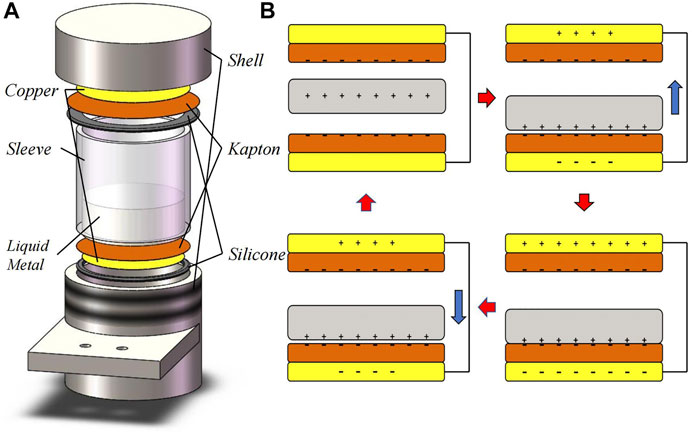
FIGURE 3. (A) Schematic illustration showing the device configuration of the triboelectric device; (B) Step-by-step illustration showing the working principle of the triboelectric device.
The complete working principle of the triboelectric device is shown in Figure 3B. Because Liquid metal and Kapton have different capabilities to absorb electrons, when liquid metal contacts Kapton, the electrons are transformed from liquid metal to the surface of Kapton, making the Kapton has negative charges and liquid metal has positive charges. After the liquid metal contacts the upper and lower Kaptons, the Kapton has negative charges, and the liquid metal has positive charges. Take this moment as the initial state. Before the liquid metal touches the lower Kapton, the positive charges of the liquid metal strip offset the negative charges of part of the lower Kapton strip, causing the electric field balance of the upper and lower Kaptons to be broken, and generates an upward current until the liquid metal is in full contact with Kapton. When the liquid metal separates from the Kapton upwards, the electric field between the liquid metal and the lower Kapton weakens, causing the electric field balance between the two Kaptons to be broken and generates a downward current. The process of contact between liquid metal and upper Kapton is similar to this process. The pulse output of the entire process exhibits characteristics of AC.
The working principle of the triboelectric device shows that if liquid metal contacts and separates from Kapton, the device will generate electricity. The triboelectric device is simply regarded as a cylindrical container filled with some liquid inside, regardless of the placement position, the external excitations in all directions can cause the internal liquid to hit both ends of the container. These characteristics also make this triboelectric device owns the capability of multidirectional vibration harvesting. The model is a full-size device that can be applied to moving yachts, cars and other vehicles to provide electrical power to their electrical equipment. Since the stern of the yacht has a large swing, we can install multiple TENGs to the stern of the yacht, as shown in Figure 4B. For automobiles, the vibration of the inner wheel measurement is larger, we can install it to the inner wheel measurement, as shown in Figure 4A.
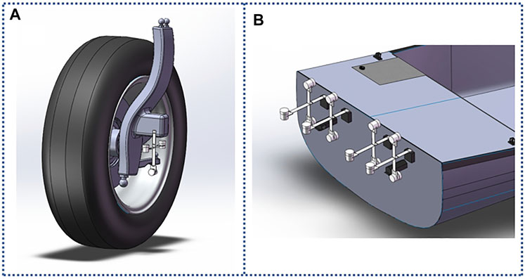
FIGURE 4. (A) Diagram of installation in a car; (B) Diagram of the installation on the yacht.
Experiment
To verify the effects of multi-modal vibration of the multi-modal device on broadening the working frequency band and multi-directional energy harvesting, a single-modal device is used as a comparison. The single-modal device’s material and geometric parameters are the same as the main cantilever beam in the multi-modal device’s component. In the following experiments, the vibration table provides horizontal and vertical swept excitation from 2 to 22 Hz, respectively. Under such external excitation, we compare dynamic strain, open-circuit voltage, energy density, lighting capability, and capacitor charging capability of the single-modal device and the multi-modal device. The experimental setup is shown in Figure 5B.
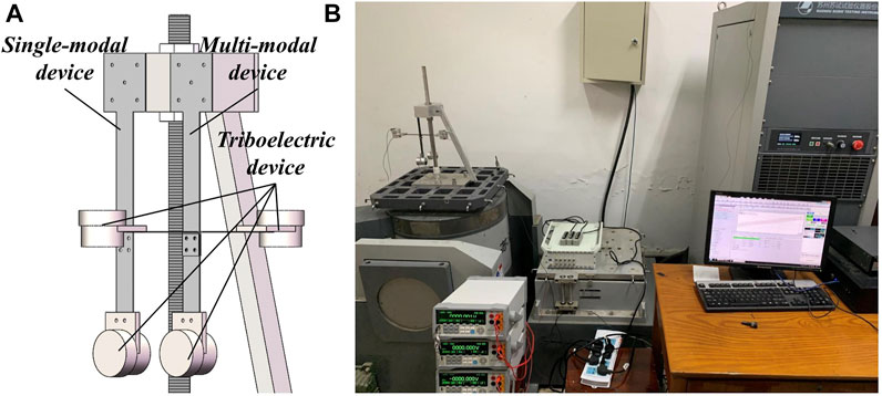
FIGURE 5. (A) Installation diagram of multi-modal device and single-modal device; (B) The experimental setup.
Dynamic Stress Experiment
During the bending deformation of the cantilever beam, the normal strain at the root of the beam is directly proportional to the vibration displacement of the free end. Therefore, the dynamic response of the cantilever beam can be explored by measuring its dynamic strain. Three resistance strain gages are attached to the root of the single-modal device, the root of the vertical cantilever in the multi-modal device, and the root of one branch in the multi-modal device. Use the vibration table to provide horizontal and vertical sinusoidal frequency sweep excitation. Figure 6 presents the results of the dynamic strain of the single-modal device and multi-modal device under a peak-to-peak excitation of 2 mm, with the excitation frequency f swept from 2 to 22 Hz at a frequency rise rate of 0.1 Hz/s.
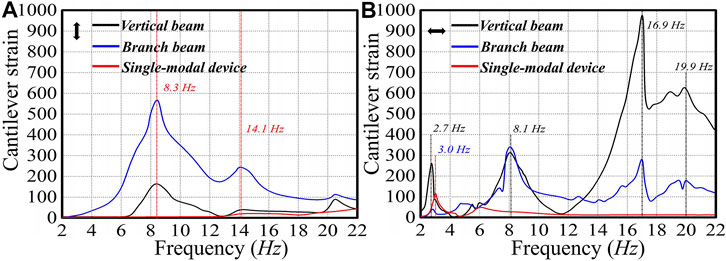
FIGURE 6. Cantilever strain of frequency-sweep test under 2 mm peak-to-peak excitation at 2–22 Hz sweep frequency: (A) Cantilever strain of multi-modal device and single-modal device in vertical incentive; (B) Cantilever strain of multi-modal device and single-modal device in horizontal incentive.
As shown in Figure 6B, the strain of the vertical cantilever beam reaches a peak at 2.7 Hz. At this time, the strain reaches 254.8 × 10⁻⁶, while the branch beam has no obvious strain. The structural deformation is mainly the bending deformation of the vertical cantilever beam. According to the simulation results in the previous section, the first-order natural frequency of the multi-modal device is 2.8 Hz, and the structural deformation is also consistent with the experimental results. The simulation results show that the cross beam device has a vibration mode of torsion of the vertical cantilever beam at 5.7 Hz. However, since the vibration table can only provide a single degree of freedom vibration excitation and can not provide torsional excitation, the torsional vibration mode is not observed in the experiment.
In the simulation, the third-order vibration mode appears at 8.4 Hz and the deformation of the structure is not only the bending deformation of the vertical cantilever beam in the horizontal direction but also the bending deformation of the two branches in the vertical direction. Therefore, it can be seen from Figure 6 that not only when the horizontal excitation reaches 8.1 Hz, the strain of the vertical cantilever beam and the branch reaches a peak but also when the vertical excitation reaches 8.3 Hz, the strain of both also reaches a peak. Corresponds to the third-order vibration mode in the simulation.
As shown in Figure 6A, when the excitation frequency in the vertical direction reaches 14.3 Hz, the strain of the branch of the multi-modal device reaches a peak value of 287.6 × 10⁻⁶, but the vertical beam has no obvious strain. Therefore, the deformation of the structure is mainly the bending deformation of the branch beams, which corresponds to the fourth-order vibration mode of the simulation results at 14.1 Hz.
Simulation results show that the fifth-order vibration mode occurs at 20.2 Hz. In Figure 6B, under horizontal excitation, the strain of the vertical cantilever beam reaches a peak of 624.5 × 10⁻⁶ at 19.9 Hz. The vertical beam has a large bending deformation, which is consistent with the results obtained by simulation. In addition, in Figure 6B, when the horizontal excitation frequency is 16.9 Hz, the vertical cantilever beam and the branch both resonate and the strain of the vertical cantilever beam reaches 971.2 × 10⁻⁶, which may be the result of aliasing of the fourth-order vibration mode and the fifth-order vibration mode.
For the single-modal device, since it has only a single cantilever beam, it has only one natural frequency and should have only one vibration mode. As shown in Figure 6B, only when the horizontal excitation reaches 3 Hz, the strain of the single beam device reaches a peak value of 101.6 × 10⁻⁶. For the case of vertical excitation, since the excitation direction is parallel to the cantilever beam’s direction, no obvious strain appears. These are also consistent with the theory.
The vibration conditions of single-modal device and multi-modal device under two directions of excitation are recorded by video (see Supplementary videos Multi-modal device and Single-modal device). It can be seen intuitively that the vibration conditions of multi-modal devices are basically consistent with the simulation results. In particular, the multi-modal device has a wider vibration frequency band and the capability of multi-directional energy harvesting.
Open-Circuit Voltage Output Characteristics Experiment
Since the vibration modes of the multi-modal device are complicated and the triboelectric device based on liquid metal has multi-directional vibration harvesting capability, the displacement measurement of a fixed point can not reflect the harvesting capability of the energy harvester. The research on the multi-modal device’s broadband harvesting capability in multiply directions also needs to be performed by measuring the open-circuit voltage of the device.
Still using the shaking table to provide the same horizontal and vertical sine sweep excitation as the dynamic strain experimental conditions. For multi-modal devices, the output of three triboelectric devices is connected in series after passing through the rectifier bridge. Then measure the multi-modal device’s output with a desktop multimeter. The output of the single-mode device is connected to the desktop multimeter after passing through the rectifier bridge.
Under vertical excitation, the single-modal device is parallel to the vibration direction, so its cantilever beam does not have a vibration in the horizontal direction. However, as shown in Figure 7A, the single-modal device has an open-circuit voltage output between 14.1 and 22 Hz (the effective frequency bands are defined as a frequency band with the open-circuit voltage of 10 V or more) and reaches the peak voltage of 22.8 V at 21.6 Hz. This is because the triboelectric device of a single-modal device vibrates in the vertical direction with the shaking table and the triboelectric device itself has the capability of multi-directional energy harvesting. The multi-modal device has two working frequency bands (6.9 Hz–12 Hz; 13.9 Hz–22 Hz) and the open-circuit output voltage of it is generally higher than the open-circuit output voltage of the single-modal device. It can be seen from the experiment of dynamic strain that the multi-modal device resonates around 8.3 and 14.1Hz, but the strain of the branch at 14.1 Hz is much smaller than that at 8.3 Hz. Small amplitude can not make the liquid metal in the triboelectric device touch the upper surface of the device. So under vertical excitation, the open-circuit output voltage of a multi-modal device can reach 44.1 V (193% of the peak voltage of the single-modal device). In addition, due to the multi-directional collection capability of the triboelectric device, after 18 Hz, as the frequency increases, the open-circuit voltage gradually increases.
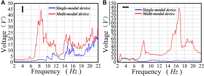
FIGURE 7. Open circuit voltage of frequency-sweep test under 2 mm peak-to-peak excitation at 2–22 Hz sweep frequency:(A) Open circuit voltage of multi-modal device and single-modal device in vertical incentive; (B) Open circuit voltage of multi-modal device and single-modal device in horizontal incentive.
Figure 7B shows the open-circuit voltage output characteristics of single-modal devices and multi-modal devices under horizontal excitation. The working frequency band of single-modal devices is only from 2.8 to 6.0 Hz, and the maximum output of the triboelectric device1 is only 12.8 V. Typically, this is caused by two factors. One of the reasons is that the single-modal device is a single cantilever beam structure, so it has only one resonance point (3.0 Hz) and generates a large vibration near the resonance point. The second reason can be that since the peak-to-peak excitation is very small (2 mm) and the vibration direction is perpendicular to the cantilever beam, the cantilever beam acts as a shock absorber in the frequency band above the resonance point, keeping the single-modal device stationary relative to the ground. This also explains why the triboelectric device itself can collect in multiple directions, but it can not output voltage in the rear frequency band like when it is under vertical excitation. The open-circuit output voltage of multi-mode equipment has three peaks (2.9 Hz, 21.8 V; 8.1 Hz, 55.8 V; 16.8 Hz, 138.6 V) and reaches the peak open-circuit voltage at 20 Hz. This is because the mixing of the fourth-order vibration mode and the fifth-order vibration mode makes the multimode device produce severe vibration. The peak open-circuit voltage of the multi-modal device is 1082% of that of the single-modal device (12.8 V). The working frequency band of a multi-modal device is 2–22 Hz, which is 6.25 times that of the single-mode device.
These experimental results prove that the multi-modal vibration of the multi-modal device significantly improves the width of the working frequency band and the capability of the device to harvest multidirectional vibration energy.
Power-Density Experiment
The power density, being the output power to weight ratio (W/kg), is an important parameter to measure the quality of the power supply. In order to compare the optimal power density of the single-modal device and multi-modal device under two directions of excitation, it is necessary to determine the optimal impedance of the multi-modal device by measuring the basic output of that. The basic output of the multi-modal devices (the output voltage, the output current, and output power) is measured under a horizontal excitation with constant frequency (8 Hz) and peak-to-peak value (2 mm). After connecting the multi-modal device to the resistance box, the output voltage and current of the multi-modal device (Figure 8A) is measured by changing the resistance and the output power is calculated under different loads (Figure 8B). The optimal impedance is equal to the external load when the maximum output power is obtained. By observing Figure 8B, the optimal impedance of multi-modal devices is about 8 MΩ.
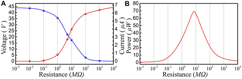
FIGURE 8. Basic output of multi-modal device under an horizontal excitation with constant frequency (8 Hz) and peak-to-peak value (2 mm). (A) Output voltage and output current of multi-modal device under different resistance values; (B) The output power of multi-modal device at different resistance values.
According to the principle of impedance matching, under the same conditions as the excitation in the previous section, the 8 M resistor is used as load resistance. The power density of the device can be calculated by formula P = U2/(RM), where U, R, and M are output voltage, load resistance, and mass of the device (the masses of the single-modal device and multi-modal device are 289.6 and 811.3 g, respectively). The optimal power density is shown in Figure 9.
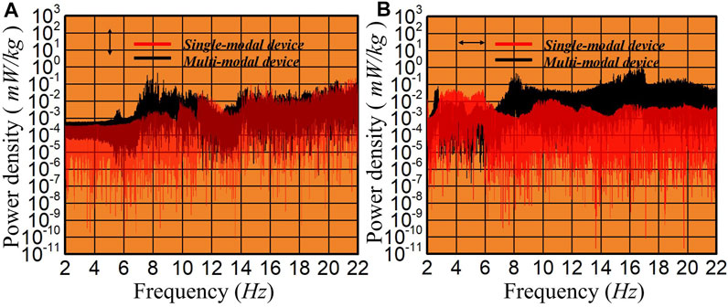
FIGURE 9. Power density of frequency-sweep test under 2 mm peak-to-peak excitation at 2–22 Hz sweep frequency: (A) Power density of multi-modal device and single-modal device in vertical incentive; (B) Power density of multi-modal device and single-modal device in horizontal incentive.
As shown in Figure 9A, under vertical excitation, since the single-modal device basically does not generate vibration and completely relies on the triboelectric device’s multi-directional harvesting capability to generate electrical energy, the power density shows an upward trend with the frequency. For the power density of multi-modal devices, the maximum power density of multi-modal devices, which appears between 7.6 and 11.8 Hz, is 2.48 × 10⁻¹ mW/kg. It is worth noting that the optimal power density of multi-modal devices is generally higher than that of the single-modal device in the full frequency band. In Figure 8B, under horizontal excitation, the contrast between them is more obvious. The power density graph of multi-modal device has four peaks (8 × 10⁻² mW/kg, 2.7 Hz; 4.5 × 10⁻¹ mW/kg, 7.9 Hz; 1.25 × 10−0mW/kg, 16.5 Hz; 2.1 × 10⁻¹ mW/kg, 19.7 Hz), corresponding to its four resonances, while single-modal device has only one peak (5.5 × 10⁻²mW/kg, 3.4 Hz). In addition, the optimal power density of multi-modal devices is better than that of single-modal devices in all resonance frequency bands of multi-modal devices and the peak output power density of multi-modal devices is 2272% of the single beam devices. The higher energy density of multi-modal devices means that they can output more power. In Supplementary video Single-modal devices and Multi-modal devices, under the same horizontal excitation as the previous frequency sweep range, single-modal devices, and multi-modal devices are connected to 36 LEDs, respectively. It can be clearly seen that the 36 LEDs connected to multi-modal devices are brighter and flash in a wider frequency range in videos.
The above experimental results show that the output power density of a multi-modal device is significantly better than that of a single-modal device. This structure enables the device to have multi-modal characteristics, which not only broadens the working frequency band in the low-frequency range but also increases the output power of the energy harvester in multiple directions.
Power Generation Experiment
After studying the effects of the multi-modal characteristics on the open-circuit voltage, working frequency band, and power density, the following step is to compare the energy harvesting efficiency (generation efficiency) of single-modal devices and multi-modal devices by charging the capacitor. The sweep frequency range and amplitude remain unchanged, while the frequency rise rate is changed to 0.3 Hz/s, which causes the sweep time to 65 s. In addition, the output of the triboelectric device is converted to direct current by connecting to a rectifier bridge, the output of which is connected in parallel to a capacitor of 10 μF for charging. The experimental results are plotted in Figure 10. In addition, in order to verify the power generation effect of multi-modal devices in the natural environment, we simulated the wave experiment.
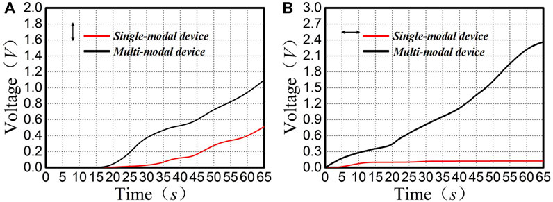
FIGURE 10. Voltage of 10 μF capacitor charged by multi-modal device and single-modal device: (A) Capacitor voltage of multi-modal device and single-modal device in vertical incentive; (B) Capacitor voltage of multi-modal device and single-modal device in horizontal incentive.
As shown in Figure 10A, under the vertical excitation, although the multi-directional energy harvesting capability of the triboelectric device makes the voltage of capacitance powered by single-mode devices reach 0.498 V, the multi-modal characteristics of multi-modal device make the Charging speed of the capacitor connected to it is always faster than that of single-modal device. After the frequency sweep, the voltage of the capacitor connected to a multi-modal device reaches 1.09 V, which is 218% of that of a single-modal device.
Under horizontal excitation, the contrast shown in Figure 10B is more obvious. Because single-modal devices have almost no power output in this case, the voltage of the capacitor connected to them does not change significantly in the entire frequency band. Due to the frequency band of the multi-mode device covering the full frequency of 2–22 hz, it can be seen that the voltage of the capacitor powered by it has been increasing (reaching 2.36 V at last, which is 1815% of that of the single-modal device). These results prove once again that the traditional vibration energy harvester, which is a single cantilever beam structure, can’t work under multi-directional micro-vibration excitation. Typically, the multi-modal device improves energy harvesting efficiency as a result of its multi-modal characteristics.
In wave experiment (see Supplementary video wave experiments), first pour an appropriate amount of water into the pool, then fix the multi-modal device on the simulation buoy, and use the wave machine to simulate ocean waves. Under the waves generated by the wave machine, the output of the multi-modal device easily lightened 24 LEDs. The results show that multi-modal devices have a good response to low-frequency and multi-directional excitation, which means it has the potential to harvest low-frequency and multi-directional vibration energy like wave energy. The multi-modal equipment can be installed on buoys and ships, harvesting wave energy and converting wave energy into electrical energy and storing electrical energy in batteries, and then supplying power to the low-power devices on the buoys and ships.
Practical Environment Working Testing Experiment
The power density experiment verifies the working quality of the multi-mode energy collection device as a power supply in an ideal working environment. In order to further explore the connection between ideal and actual operating characteristics of multi-mode energy collection device, the experiment is designed to explore the relationship between the working effect of multi-mode energy collection device in simulating the actual working environment and the experimental data obtained by power density experiment.
The multi-mode energy collection device is designed for collecting wave energy and installed on ships and automobiles to collect vibration energy generated during their movement. The acceleration sensors are mounted on vertical and horizontal cantilever beams respectively. Since the base of the device is fixed, it moves in synchronization with the yacht in the horizontal direction. The acceleration of vertical and horizontal cantilever beams of the multi-mode energy collection device during yacht sailing is measured with time. Combined with the results of power generation experiment, the relationship between vibration acceleration and energy density of vertical and horizontal cantilever beams in the actual working environment is studied.
During the experiment, the horizontal cantilever beam and yacht remain relatively static in the horizontal direction and move in a straight line with uniform velocity, but move irregularly in the vertical direction under the influence of waves. During the experiment, it is found that the vibration intensity of the horizontal cantilever beam is significantly higher than that of the vertical cantilever beam.
To minimize the influence of environmental interference during the experiment, the measurement data of yacht during the period of steady sailing during the experiment is selected for experimental analysis, and the part is selected from 68.000 to 122.236 s as the actual result data. As shown in Figure 11A, when the yacht is stationary, the acceleration of the vertical and horizontal cantilever beams remain unchanged with time. The average maximum acceleration of vertical cantilever beam is about 2 m/s2, and that of horizontal Cantilever beam is about 4 m/s2. The overall acceleration of the horizontal cantilever beam is about twice that of the vertical cantilever beam. Combined with the data obtained by the power density experiment, the maximum power density of the multi-mode energy collection device basically remains unchanged at the non-resonant point. As shown in Figure 9A, under vertical excitation, the maximum power density of the multi-mode device is 0.4 m/s2. In Figure 9B, the maximum power density of the multi-mode device reaches 16 mW/kg under horizontal excitation. The ideal working characteristic of the multi-mode energy collection device can be approximated as the superposition of the maximum power density in horizontal and vertical directions. The maximum power density of the muti-mode energy collection device is 8.2 times of the maximum acceleration of the vertical cantilever beam and 4.1 times of the maximum acceleration of the horizontal cantilever beam.
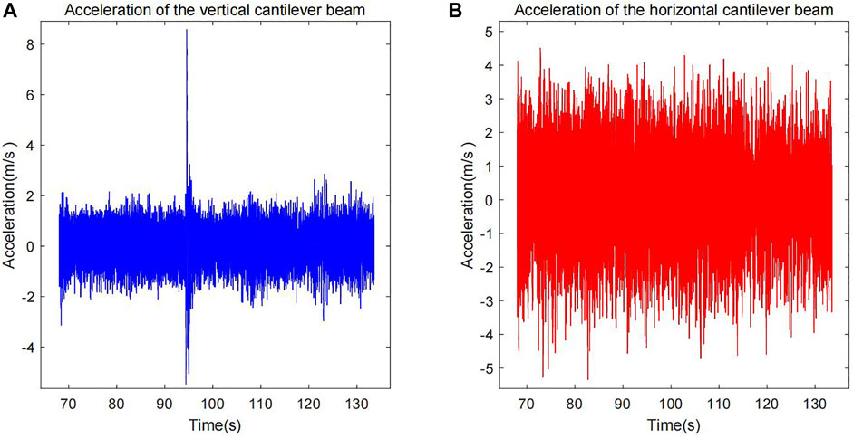
FIGURE 11. The recorded acceleration data of the vertical and horizontal cantilever beam from 68.000 to 122.236s: (A) acceleration of the vertical cantilever beam from 68.000 to 122.236s; (B) acceleration of the horizontal cantilever beam from 68.000 to 122.236s.
The maximum power density of the multi-mode energy collection device under stable operating conditions, The relationship between the maximum power density and the maximum acceleration can be used to approximate the relationship between the ideal working characteristics and the actual working characteristics.
Conclusion
A multi-modal energy harvesting device using a crossed beam, suitable for multi-directional and broadband energy harvesting in the low-frequency range, has been proposed. Modal simulation shows that the structure of a multi-modal device has five vibration modes in the low-frequency range below 22 Hz. Dynamic strain experiment verifies the correctness of the simulation results and further reveals the multi-modal characteristics of this structure. It can be seen in the multi-directional sweep comparison experiments that the device proposed in this letter is superior in various data. In contrast to single-modal devices, multi-modal devices increase the working frequency band to 6.25 times, the peak open-circuit voltage increases to 1082%, and the power generation of multi-modal devices increase to 1815%. Notably, the peak power densities of multi-modal devices can reach 1.25 mW/kg, which increases to 2227%, so that it has enough power to light up 36 LEDs in series in a wide frequency band. In addition, multi-modal devices can light up 24 LEDs under the waves. By virtue of this multi-modal vibration, multi-modal devices not only are able to harvest multi-frequency vibrational energy in multiple directions but also have high power generation efficiency and potential value. The multi-modal device, which combines the cross beam structure and the triboelectric devices based on the liquid metal, provides a welcome boost for the development of the vibration energy harvester.
Data Availability Statement
The original contributions presented in the study are included in the article/supplementary material, further inquiries can be directed to the corresponding authors.
Author Contributions
YZ and ZY have contributed to the acquisition data, analysis data, and drafting the article. These two authors have contributed equally to this work. CJ, MM and XZ have contributed to analysis data, interpretation data, and revising the article. All the authors have contributed to final proof reading and approval of the version for publication.
Conflict of Interest
The authors declare that the research was conducted in the absence of any commercial or financial relationships that could be construed as a potential conflict of interest.
Publisher’s Note
All claims expressed in this article are solely those of the authors and do not necessarily represent those of their affiliated organizations, or those of the publisher, the editors and the reviewers. Any product that may be evaluated in this article, or claim that may be made by its manufacturer, is not guaranteed or endorsed by the publisher.
Acknowledgments
The authors appreciate the support of the National Natural Science Foundation of China (Grant Nos.. 11872167, 51775164, and 51705122) and Natural Science Foundation of Anhui Province(1908085J15).
References
Andó, B., Baglio, S., Maiorca, F., and Trigona, C. (2012). Two Dimensional Bistable Vibration Energy Harvester. Procedia Eng. 47, 1061–1064. doi:10.1016/j.proeng.2012.09.333
Arrieta, A. F., Hagedorn, P., Erturk, A., and Inman, D. J. (2010). A Piezoelectric Bistable Plate for Nonlinear Broadband Energy Harvesting. Appl. Phys. Lett. 97, 104102. doi:10.1063/1.3487780
Chen, B. D., Tang, W., He, C., Deng, C. R., Yang, L. J., Zhu, L. P., et al. (2018). Water Wave Energy Harvesting and Self-Powered Liquid-Surface Fluctuation Sensing Based on Bionic-Jellyfish Triboelectric Nanogenerator. Mater. Today 21, 88–97. doi:10.1016/j.mattod.2017.10.006
Deng, H., Ye, J., Du, Y., Zhang, J., Ma, M., and Zhong, X. (2019). Bistable Broadband Hybrid Generator for Ultralow-Frequency Rectilinear Motion. Nano Energy 65, 103973. doi:10.1016/j.nanoen.2019.103973
Erturk, A., and Inman, D. J. (2008). A Distributed Parameter Electromechanical Model for Cantilevered Piezoelectric Energy Harvesters. J. Vib. Acoust. 130, 402. doi:10.1115/1.2890402
Erturk, A., and Inman, D. J. (2009). An Experimentally Validated Bimorph Cantilever Model for Piezoelectric Energy Harvesting from Base Excitations. Smart Mat. Struct. 18, 025009. doi:10.1088/0964-1726/18/2/025009
Fan, F.-R., Lin, L., Zhu, G., Wu, W., Zhang, R., and Wang, Z. L. (2012a). Transparent Triboelectric Nanogenerators and Self-Powered Pressure Sensors Based on Micropatterned Plastic Films. Nano Lett. 12, 3109–3114. doi:10.1021/nl300988z
Fan, F.-R., Tian, Z.-Q., and Lin Wang, Z. (2012b). Flexible Triboelectric Generator. Nano Energy 1, 328–334. doi:10.1016/j.nanoen.2012.01.004
Fan, F.-R., Tian, Z.-Q., and Lin Wang, Z. (2012). Flexible Triboelectric Generator. Nano energy 1, 328–334. doi:10.1016/j.nanoen.2012.01.004
Friswell, M. I., Ali, S. F., Bilgen, O., Adhikari, S., Lees, A. W., and Litak, G. (2012). Non-linear Piezoelectric Vibration Energy Harvesting from a Vertical Cantilever Beam with Tip Mass. J. Intelligent Material Syst. Struct. 23, 1505–1521. doi:10.1177/1045389x12455722
Harne, R. L., and Wang, K. W. (2013). A Review of the Recent Research on Vibration Energy Harvesting via Bistable Systems. Smart Mat. Struct. 22, 023001. doi:10.1088/0964-1726/22/2/023001
Hu, Y., Yang, J., Jing, Q., Niu, S., Wu, W., and Wang, Z. L. (2013). Triboelectric Nanogenerator Built on Suspended 3d Spiral Structure as Vibration and Positioning Sensor and Wave Energy Harvester. Acs Nano 7, 10424–10432. doi:10.1021/nn405209u
Ibrahim, S. W., and Ali, W. G. (2012). A Review on Frequency Tuning Methods for Piezoelectric Energy Harvesting Systems. J. Renew. Sustain. Energy 4, 062703. doi:10.1063/1.4766892
Kim, H. S., Kim, J.-H., and Kim, J. (2011a). A Review of Piezoelectric Energy Harvesting Based on Vibration. Int. J. Precis. Eng. Manuf. 12, 1129–1141. doi:10.1007/s12541-011-0151-3
Kim, I.-H., Jung, H.-J., Lee, B. M., and Jang, S.-J. (2011b). Broadband Energy-Harvesting Using a Two Degree-Of-Freedom Vibrating Body. Appl. Phys. Lett. 98, 214102. doi:10.1063/1.3595278
Li, H., Tian, C., and Deng, Z. D. (2014). Energy Harvesting from Low Frequency Applications Using Piezoelectric Materials. Appl. Phys. Rev. 1, 041301. doi:10.1063/1.4900845
Pellegrini, S. P., Tolou, N., Schenk, M., and Herder, J. L. (2013). Bistable Vibration Energy Harvesters: a Review. J. Intelligent Material Syst. Struct. 24, 1303–1312. doi:10.1177/1045389x12444940
Sodano, H. A., Park, G., and Inman, D. J. (2004). Estimation of Electric Charge Output for Piezoelectric Energy Harvesting. Strain 40, 49–58. doi:10.1111/j.1475-1305.2004.00120.x
Tadesse, Y., Shujun Zhang, S., and Priya, S. (2009). Multimodal Energy Harvesting System: Piezoelectric and Electromagnetic. J. Intelligent Material Syst. Struct. 20, 625–632. doi:10.1177/1045389x08099965
Tang, W., Jiang, T., Fan, F. R., Yu, A. F., Zhang, C., Cao, X., et al. (2015). Liquid-metal Electrode for High-Performance Triboelectric Nanogenerator at an Instantaneous Energy Conversion Efficiency of 70.6%. Adv. Funct. Mater. 25, 3718–3725.
Toprak, A., and Tigli, O. (2014). Piezoelectric Energy Harvesting: State-Of-The-Art and Challenges. Appl. Phys. Rev. 1, 031104. doi:10.1063/1.4896166
Toyabur, R. M., Salauddin, M., Cho, H., and Park, J. Y. (2018). A Multimodal Hybrid Energy Harvester Based on Piezoelectric-Electromagnetic Mechanisms for Low-Frequency Ambient Vibrations. Energy Convers. Manag. 168, 454–466. doi:10.1016/j.enconman.2018.05.018
Wang, K., Hu, F., Mao, M., Liu, Y., and Wang, H. (2016). “Design of a Multi-Directional Piezoelectric Energy Harvester with Spring and Magnetic Coupling,” in 2016 IEEE International Conference on Power and Renewable Energy (ICPRE) (Shanghai: IEEE), 126–129. doi:10.1109/icpre.2016.7871186
Wang, S., Ding, L., Fan, X., Jiang, W., and Gong, X. (2018). A Liquid Metal-Based Triboelectric Nanogenerator as Stretchable Electronics for Safeguarding and Self-Powered Mechanosensing. Nano energy 53, 863–870. doi:10.1016/j.nanoen.2018.09.035
Wang, Z. L. (2017). On Maxwell's Displacement Current for Energy and Sensors: the Origin of Nanogenerators. Mater. Today 20, 74–82. doi:10.1016/j.mattod.2016.12.001
Wang, Z. L. (2013). Triboelectric Nanogenerators as New Energy Technology for Self-Powered Systems and as Active Mechanical and Chemical Sensors. ACS Nano 7, 9533–9557. doi:10.1021/nn404614z
Wu, N., Wang, Q., and Xie, X. (2015). Ocean Wave Energy Harvesting with a Piezoelectric Coupled Buoy Structure. Appl. Ocean Res. 50, 110–118. doi:10.1016/j.apor.2015.01.004
Wu, Y., Qiu, J., Zhou, S., Ji, H., Chen, Y., and Li, S. (2018). A Piezoelectric Spring Pendulum Oscillator Used for Multi-Directional and Ultra-low Frequency Vibration Energy Harvesting. Appl. energy 231, 600–614. doi:10.1016/j.apenergy.2018.09.082
Xu, J., and Tang, J. (2017). Modeling and Analysis of Piezoelectric Cantilever-Pendulum System for Multi-Directional Energy Harvesting. J. Intelligent Material Syst. Struct. 28, 323–338. doi:10.1177/1045389X16642302
Xu, J., and Tang, J. (2015). Multi-directional Energy Harvesting by Piezoelectric Cantilever-Pendulum with Internal Resonance. Appl. Phys. Lett. 107, 213902. doi:10.1063/1.4936607
Yang, Y., Lin, L., Zhang, Y., Jing, Q., Hou, T.-C., and Wang, Z. L. (2012). Self-Powered Magnetic Sensor Based on a Triboelectric Nanogenerator. ACS Nano 6, 10378–10383. doi:10.1021/nn304374m
Yang, Y., Sun, N., Wen, Z., Cheng, P., Zheng, H., Shao, H., et al. (2018). Liquid-metal-based Super-stretchable and Structure-Designable Triboelectric Nanogenerator for Wearable Electronics. ACS Nano 12, 2027–2034. doi:10.1021/acsnano.8b00147
Zhang, B., Zhang, L., Deng, W., Jin, L., Chun, F., Pan, H., et al. (2017). Self-powered Acceleration Sensor Based on Liquid Metal Triboelectric Nanogenerator for Vibration Monitoring. ACS Nano 11, 7440–7446. doi:10.1021/acsnano.7b03818
Zhang, C., Tang, W., Han, C., Fan, F., and Wang, Z. L. (2014). Theoretical Comparison, Equivalent Transformation, and Conjunction Operations of Electromagnetic Induction Generator and Triboelectric Nanogenerator for Harvesting Mechanical Energy. Adv. Mat. 26, 3580–3591. doi:10.1002/adma.201400207
Zhang, L. M., Han, C. B., Jiang, T., Zhou, T., Li, X. H., Zhang, C., et al. (2016). Multilayer Wavy-Structured Robust Triboelectric Nanogenerator for Harvesting Water Wave Energy. Nano Energy 22, 87–94. doi:10.1016/j.nanoen.2016.01.009
Zhao, J., Yang, J., Lin, Z., Zhao, N., Liu, J., Wen, Y., et al. (2015). An Arc-Shaped Piezoelectric Generator for Multi-Directional Wind Energy Harvesting. Sensors Actuators A Phys. 236, 173–179. doi:10.1016/j.sna.2015.10.047
Zhou, S., Cao, J., Erturk, A., and Lin, J. (2013). Enhanced Broadband Piezoelectric Energy Harvesting Using Rotatable Magnets. Appl. Phys. Lett. 102, 173901. doi:10.1063/1.4803445
Keywords: multi-modal, multi-directional, low-frequency, broadband, cross beam, wave energy
Citation: Zhu Y, Yang Z, Jiao C, Ma M and Zhong X (2022) A Multi-Modal Energy Harvesting Device for Multi-Directional and Low-Frequency Wave Energy. Front. Mater. 9:898921. doi: 10.3389/fmats.2022.898921
Received: 18 March 2022; Accepted: 19 April 2022;
Published: 03 May 2022.
Edited by:
Wenai Shen, Huazhong University of Science and Technology, ChinaReviewed by:
Shuaishuai Sun, University of Science and Technology of China, ChinaAgathoklis Giaralis, City University of London, United Kingdom
Copyright © 2022 Zhu, Yang, Jiao, Ma and Zhong. This is an open-access article distributed under the terms of the Creative Commons Attribution License (CC BY). The use, distribution or reproduction in other forums is permitted, provided the original author(s) and the copyright owner(s) are credited and that the original publication in this journal is cited, in accordance with accepted academic practice. No use, distribution or reproduction is permitted which does not comply with these terms.
*Correspondence: Mengchao Ma, bW1jaGFvQGhmdXQuZWR1LmNu Xiang Zhong, emh4MDMyNUBoZnV0LmVkdS5jbg==
†These authors have contributed equally to this work and share first authorship