 Nathalie Kölbl
94% of researchers rate our articles as excellent or good
Learn more about the work of our research integrity team to safeguard the quality of each article we publish.
Find out more
REVIEW article
Front. Mater., 17 May 2022
Sec. Structural Materials
Volume 9 - 2022 | https://doi.org/10.3389/fmats.2022.881168
This article is part of the Research TopicFluxes and Steel QualityView all 5 articles
In the continuous casting of steel, the melting behavior of mold powders influences the slag pool thickness and slab quality. Various methods have been implemented in laboratories to investigate this property, and in particular, melting rates are of interest. This study aimed to assess the existing methods with respect to their ability to determine melting rates under service-related conditions and to develop criteria for this purpose. These methods are divided into two groups, one of which can provide the necessary heat-transfer coefficient owing to the application of a preheated furnace or steel bath. The second condition is a sufficiently low mold powder layer thickness to allow for the desired mean heating rate. For the case study, the required heating rate is determined, and the maximum limit for this layer thickness is calculated from the conditions for Fourier and Biot numbers of varying test setups. Suitable test arrangements are also identified.
In the continuous casting of steel, mold powder is added on top of the liquid steel in the copper mold. The heat flux from the steel causes the raw material particles, which are not in equilibrium, to react with each other. First, new solid and discontinuous intermediate liquid phases arise at relatively low temperatures; with increasing temperature, a continuous and homogeneous liquid is formed (Kromhout, 2013; Münch et al., 2018; Marschall et al., 2019). Consequently, three vertical layers can be distinguished on the steel pool: a homogeneous liquid in contact with the metal, a sintered layer partly containing intermediate liquid phases, and the original mold powder in contact with the atmosphere. The slag was entrapped in the area between the steel strand and mold, lubricating the newly formed steel shell. In the horizontal direction, three layers are formed controlling the horizontal heat flux and the subsequent cooling of the strand (Mills and Fox, 2003).
The melting behavior of the mold powder plays an essential role for reliable steady-state operating conditions. Consequently, several laboratory tests have been established to characterize the melting behavior of mold powders utilizing various methods. Nevertheless, not all of them represent the conditions in the mold during the continuous casting of steel. Hence, in this study, existing methods are summarized and discussed with reference to process conditions.
The laboratory tests from the literature are summarized in the following text. They were divided into two groups based on the heating rate of the mold powder.
A hot stage microscope was utilized to characterize the melting behavior (M1, Table 1) (Kölbl and Harmuth, 2008). Reflected light microscopy was utilized to observe a small, pressed, or pressed and polished sample during the hot stage with heating of 10°C min−1, until a homogeneous liquid emerged. Reactions taking place with increasing temperature were observed in situ. Thus, this method does not result in a melting rate; however, further information is needed to understand the melting behavior of the mold powders. In addition, methods applied for the characterization of other materials are utilized to investigate the melting behavior of mold powders: XRD with a heating stage (M2) (Carli and Righi, 2009; Kromhout, 2013), DTA/STA (M3) (Gronebaum and Pischke, 2007; Marschall et al., 2019), Seger cone method (M4) (Technical Committee ISO 1146, 1988), and heating microscopy (M5) as applied to the melting behavior of ashes according to DIN 51730 (2007). For the XRD measurements (M2), a thin mold powder layer was applied to a heating tape. The sample was then annealed stepwise at the selected temperatures. XRD scans were recorded at these temperatures. Using DTA/STA, small amounts of the original sample were heated at 20°C min−1 up to a predefined temperature. During equilibration, endo- and exothermic reactions were observed. The last endothermic peak was related to the formation of a homogeneous liquid phase. This may be associated with the weight loss owing to the evaporation of volatile components. For the Seger cone method (M4) (Branion, 1986), the sample was ground and shaped into a slim pyramidal cone of defined dimensions. Together with standard Seger cones, the sample cone was heat-treated at given heating rates. The softening of the mold powder cone was compared with that of standard cones and defined as the difference in the temperature at which the cone tip touches the base, minus the temperature at which it starts bending. Using a heating microscope (M5) (Pinheiro et al., 1995), the shapes of small pressed mold powder cylinders or cubes were monitored continuously during heating at 10°C min−1. The softening temperature (rounding of the corners and edges), melting temperature (hemispherical shape), and fluidity point were determined.
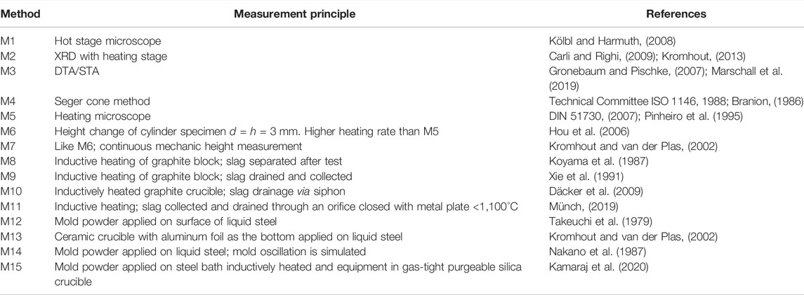
TABLE 1. Overview of methods M1–M15 as described in the text.
Contrary to the methods described in Section 2.1, laboratory methods of this group have been developed, particularly for mold powder characterization. The schematic drawings of M5‐M16 are summarized in Figure 1.
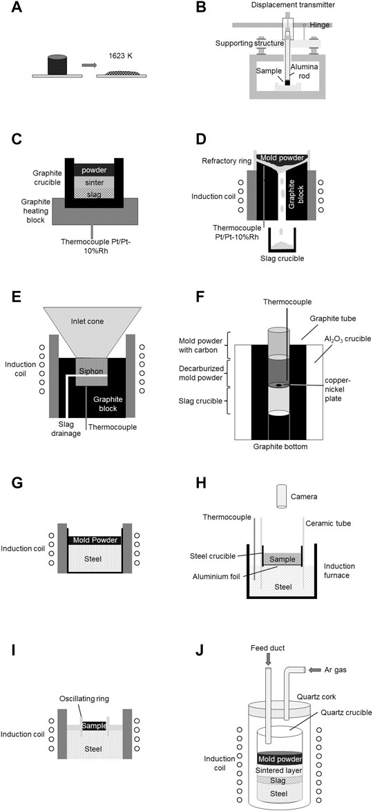
FIGURE 1. Schematic drawings of laboratory methods, where the mold powder is applied on a preheated surface according to (Hou et al., 2006), (Kromhout and van der Plas, 2002), (Koyama et al., 1987), (Xie et al., 1991), (Däcker et al., 2009), (Münch, 2019), (Takeuchi et al., 1979), (Kromhout and van der Plas, 2002), (Nakano et al., 1987), and (Kamaraj et al., 2020): (A) melting point tester (M6), (B) softening method (M7), (C) setup for the measurement of the melting rate under unidirectional heating (M8), (D) setup for the measurement of the melting rate under unidirectional heating under slag drainage (M9), (E) laboratory melting method (M10), (F) method for the simulation of mold powder layers (M11), (G) setup for the measurement of the melting rate under unidimensional heating in contact to steel (M12), (H) powder-melting method (M13), (I) setup for the investigation of the melting under oscillation (M14), and (J) method for the simulation of mold powder layers (M15).
Although the melting point tester (M6) (Hou et al., 2006) (Figure 1A) shows some similarities with the heating microscope (M5) (Pinheiro et al., 1995), it has a higher heating rate. The mold powder was pressed into a cylindrical shape with a diameter and height of 3 mm under a pressure of 1.5 MPa. After drying for 4 h at 110°C, it was inserted into a preheated furnace (1,350°C). Height changes were observed as a function of time. The melting time was defined as the point at which the sample reached 20% of its original height. The melting rate, as observed in this test, is defined by the ratio of the sample mass divided by the melting time, expressed in g s−1. The softening method (M7) is related to the testing procedure proposed by Kromhout and van der Plas (2002) (Figure 1B). It mainly differs from the application of a continuous measurement, in that the cylinder height is performed by a corundum push rod connected to a displacement gauge. The furnace temperature was chosen as 1,400°C.
The setup for measuring the melting rate under unidirectional heating (M8) (Koyama et al., 1987) (Figure 1C) uses a graphite heating block. A graphite crucible with a wall thickness, height, and inner diameter of 5, 60, and 30 mm, respectively, was positioned within its depression. A Type S thermocouple (Pt/Pt-10% Rh) located close to the crucible bottom within the graphite block enabled precise heating of the graphite block and the crucible to 1,500 ± 5°C in an induction furnace. When this temperature was attained, a predefined amount of mold powder was added to the crucible and held for 7 min. This period is based on calculations of the slag descent time in the mold from the top of the powder to the meniscus according to Delhalle et al. (1987). After the dwell, the crucible was removed for slag separation. The melting rate was calculated as the amount of slag (g) melted per unit time (min) and unit area (cm2). Further development of this setup allows for slag drainage (M9) (Xie et al., 1991) (Figure 1D). A carbon block with an inclined top and central hole was preheated within an induction coil. A Type S thermocouple enables temperature control of the surface in contact with the mold powder. In the upper part of the setup, a refractory rim was located where a predefined amount of mold powder was added to the preheated (1,500 ± 5°C) inclined surface. After liquefaction, the slag flowed to the central hole in the graphite block, passed it, and was collected in the crucible below, where it solidifies. The amount of slag collected in 7 min was used to calculate the melting rate (g s−1 cm2). This method was further improved by Däcker et al. (2009) (Figure 1E). They developed a laboratory melting method (M10), where a graphite crucible is heated with an inductor to 1,500°C bottom temperature. Mold powder was added via a water-cooled inlet cone. This enables the manual feeding of the sample to a predefined height of the crucible during testing. A controlled flow of air on the mold powder surface guarantees the oxidation of the carbon particles. Due to the siphon construction of the cylinder walls, the liquid slag flowed through elongated openings into a crucible, where it was collected as soon as a predefined slag height was formed. The mold powder consumption was calculated in kg m−2 s−1. A similar method was developed by Münch (M11) (Münch, 2019) (Figure 1F). An induction furnace that can be operated in an open state was utilized to simulate quasi-one-dimensional heating of the mold powder. For the experiment, a corundum crucible with a graphite inlet tube and graphite bottom was used. A slag-collecting crucible was placed on the graphite bottom, and another crucible with a bottom hole of 5 mm is positioned. First, the hole was closed with a copper-nickel plate (melting point ∼1,100°C) to hinder dripping of the granules into the slag-collecting crucible. The hole opened after sintering and before the mold powder melted. For the experiment, the upper crucible was half-filled with decarburized mold powder and then completely filled with the original carbon-containing powder. A Type S thermocouple was positioned close to the bottom of the crucible. Approximately 60% of the bottom of the upper crucible was heated to 1,300°C in the furnace. Münch used this method to prepare slag samples under near-service conditions. Additionally, this method can be used to measure the mold powder-melting rate after adjusting the experimental procedure, for example, defining the dwell time.
Another approach to determine the melting rate of mold powder is to apply the powder onto the surface of liquid steel. The melting rate under unidimensional heating in contact with steel (M12) (Takeuchi et al., 1979) (Figure 1G) was investigated by adding 100 g of a mold powder to the surface of 20 kg of liquid steel at a temperature of 1,500°C. The crucible containing the steel had an inner diameter of 145 mm and was preheated in a high-frequency induction furnace. The time necessary for fusion completion is a key indicator of the melting rate.
An additional device is the powder-melting method (M13) (Kromhout and van der Plas, 2002) (Figure 1H). An induction furnace with steel melt was utilized. The temperature was manually controlled using an immersed thermocouple. A steel cup, with a diameter of 70 mm and a bottom made of 0.05 mm aluminum foil, was filled with the mold powder sample. The cup was then inserted into a ceramic tube and partly immersed in liquid steel. The alumina foil immediately dissolved in the liquid steel. Using this special crucible, the mold powder is easily introduced into the furnace and added to the liquid steel surface. This procedure enables a mold powder heating rate that is comparable to that of the continuous casting process. Gas injection and stirring owing to inductive heating were possible. The video system recorded the melting process of the mold powder. The period required for complete melting of the relevant amounts of mold powder was measured.
To include the effect of mold oscillation on the melting of mold powder, an associated method (M14) (Nakano et al., 1987) (Figure 1I) was developed. Molten steel was heated to 1,550°C in an induction crucible furnace. A refractory annular ring fitted to an oscillator rod was partially immersed in liquid steel. The oscillation frequency can be selected between 0 and 200 min−1, with a stroke length of 6 mm. A predefined amount of mold powder was added to the surface of the liquid steel within the oscillating ring. After a dwell time of 7 min, the thickness of the molten slag pool was measured using the microwire technique (Ogibayashi et al., 1987). For this purpose, steel and copper wires with 1.5 mm diameter were immersed in the slag and liquid steel for 5 s. The distance between the ends of both wires represents the molten-slag-pool thickness.
Next, an additional method is presented (M15) (Kamaraj et al., 2020) (Figure 1J). A silica crucible with an inner diameter of 26 mm containing steel was placed in another silica crucible that could be sealed using a silica plug. The plug was equipped with a gas feed to provide an inert gas atmosphere via a continuous flow of argon and a mold powder feed to maintain the desired bed height. This construction was inserted into a radio frequency induction furnace. Various induction coil currents were used to simulate variable levels of electromagnetic stirring as well as varying steel temperatures. The dwell time for the experiment was defined between 30–540 s. After the experiment, the silica crucible was removed from the furnace and allowed to cool to room temperature. The respective layers of mold powder/slag were weighed separately.
It is believed that the heating rate significantly influences the liquefaction process. Furthermore, the formation of a continuous melt shifted to higher temperatures, with an increase in the heating rate. This is owing to the carbon content, which counteracts liquid formation and is oxidized at higher temperatures when heated rapidly. Furthermore, the chemical reactions between the powder components are in a high degree of disequilibrium when the heating rate increases. However, thermal equilibration must be considered for various testing methods; if all other conditions, including dwell time, remain unchanged, a higher heating rate results in a lower mean temperature with respect to volume and time. Therefore, the heating rate is a major factor in obtaining realistic results. For comparison, the mean heating rate under the service conditions was estimated for a case study based on the temperature difference and vertical powder/slag velocity. The three heating rates (HRs) are defined by Eqs 1–3, and the parameters are explained in Figure 2. The values of the continuous casting process and the calculated results are given in Tables 2, 3, respectively.
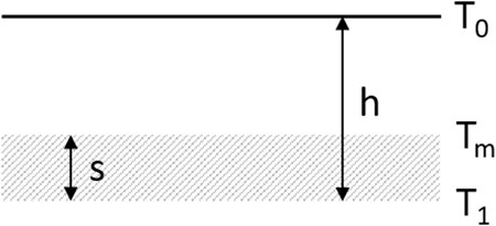
FIGURE 2. Schematic representation of mold powder/slag layers on top of the steel meniscus in the mold.
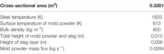
TABLE 2. Data of a case study for calculation of heating rates (HR).
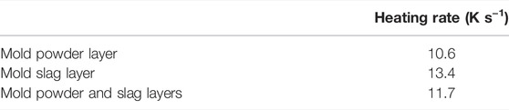
TABLE 3. HRs in the mold powder/slag layers on top of the steel meniscus in the mold.
Here, T is the absolute temperature (K), h is the total height of mold powder and slag (m), s is the height of the liquid slag on the meniscus (m), ṁ is the mold powder mass flux (kg s−1), ρ is the bulk density (kg m−3), and A is the surface area (m2). These calculations resulted in a mold powder heating rate of approximately 600°C min−1 (see Table 3 for more details). This served as comparison with the test methods summarized earlier and for later calculations concerning heat transfer. Based on these calculations, the residence time of the mold powder was approximately 100 s. This value did not agree with the 7 min determined by Delhalle (Delhalle et al., 1987). A case study with a common mold powder height of 15 mm was applied, whereas in 1987, it was approximately 50 mm. For a height of 50 mm, the heating rate of 10°C s−1 would yield a value of 5.6 min. Nevertheless, a discrepancy is still observed, which is explained by the differences in the operation of the continuous casting process, that is, increased liquid steel temperature and casting velocities. The high heating rate focuses on the heat transfer achieved using various testing methods. It is limited by several thermal and geometrical quantities that may be expressed by the Biot (Eq. 4), and Fourier (Eq. 5) numbers.
and
where α (W m−2 K−1) is the heat-transfer coefficient, L (m) is the characteristic length, λ (W m−1 K−1) is the thermal conductivity, a (m2 s−1) is the thermal diffusivity, and t (s) is the time. For a unidimensional heat flow with unilateral heating and one adiabatic surface, the characteristic length corresponds to the height of the powder bed in the laboratory experiments. In contrast, for equilateral cylindrically shaped specimens heated over the entire surface, L is lower than the cylinder diameter. Furthermore, the endothermal net energy demand impacts the temperature field, but is neglected here. This implies that the L-values estimated below are the upper limits. This simplification is sufficient to clearly distinguish between the two groups mentioned before and to identify suitable test setups, as will be demonstrated. A high heating rate is represented by a relatively low Fourier number that characterizes the experimental time, and a relatively high Biot number is necessary for sufficient heat transfer. This is explained in detail later. One way to achieve a sufficiently high heating rate is to apply non-preheated mold powder to liquid steel, which will result in an uneven transient temperature field. One reasonable strategy is to design the test setup in a way that the mean specimen temperature achieves the supposed melting temperature in a time corresponding to the heating rate representing service conditions, that is, 11.7 K s−1 (Table 3). Owing to the high heat transfer at the steel/mold powder interface, such an experimental setup will cause the interface to immediately achieve the steel temperature, that is, Bi → ∞. Then, the mean temperature depends only on Fo. This is represented in Figure 3 under the assumption of an adiabatic free upper surface, where the dimensionless mean temperature Θm is defined by
where Tm is the mean temperature of the powder specimen, Ts is the steel temperature, and T0 is the initial temperature (293 K). Figure 3 illustrates a numerical solution of the dimensionless heat conduction equation ∂Θ/∂τ = ∂2Θ∂ξ2 for different Biot numbers. Here, Θ is dimensionless temperature, and ξ and τ are dimensionless local coordinates and time, respectively. The transformation from t to τ is defined similar to the Fourier number from Eq. 5. On one interface of the one-dimensional domain of width L, the heat transfer was defined by the Biot number according to Eq. 4, and the other is assumed to be adiabatic. An example is considered: the mean target temperatures were 1523 K for liquefaction, 1808 K for the steel temperature, and 293 K for the initial temperature. These inputs yield Θm = 0.188 and Fo = 0.592, as shown in Figure 3.
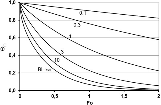
FIGURE 3. Mean dimensionless temperature for one-dimensional heat flow and one adiabatic surface in relation to Biot and Fourier number.
The heating time is calculated as (1523–293 K)/(11.7 K s−1) = 105 s. With a = 3.21 × 10⁻⁷ m2 s−1, it follows from the Fourier number that L = 7.6 mm. The thermal properties of the mold powder are listed in Tables 2, 3 using the results of Andersson (2015). Normal scenarios, using finite Biot numbers, hold for tests performed in laboratory furnaces. For a given heat-transfer coefficient, thermal diffusivity, and thermal conductivity, L is the only remaining variable in Bi and Fo. This means that the product Fo × Bi2 is fixed under these conditions and, as mentioned above, low Fo is related to high Bi. To demonstrate, the following calculation is considered: to achieve a high heat-transfer coefficient the cold sample is inserted in a furnace preheated to 1873°C. Thus, a mean heat-transfer coefficient of α = 592 W m−2 K−1 can be achieved, which is mainly owing to radiation. With a mean thermal conductivity λ = 0.167 W m−1 K−1, the thermal diffusivity Fo × Bi2 = 430 follows. Θm amounts to (1,523–1873)/(293–1873) = 0.222. For the previously mentioned condition for Fo × Bi2, this value of Θm was achieved for Fo = 0.579, Bi = 27.3, and L = 7.7 mm. This value is close to the result for Bi → ∞ and slightly higher as the furnace temperature was chosen to be higher than the steel temperature (Figure 3). For a higher layer thickness, the desired heating rate could not be achieved. The calculation shows that both layer thickness and time should be accurately defined for service-related trials; an excessive residence time would fail to depict the kinetics of the melting behavior. The relationship between the heating and melting rates should be explained in more detail. Incongruent dissolution mainly occurs, and its kinetics are controlled via diffusion in the melt. The linear dissolution rate v (m s−1) can be represented by the Stefan condition (Eq. 7):
Here, D is the effective binary diffusivity, δ is the effective diffusive boundary layer thickness, ρl and ρs are the liquid and solid densities, respectively, ws is the solubility of the dissolving species (mass%/100) at the solid/liquid interface, and w0 is its content in the liquid bulk. As D and ws increase, the absolute value of v increases. Furthermore, an increasing heating rate increases the deviation from the quasi-steady-state dissolution and tends to decrease δ, again increasing v. Increasing the heating rate decreases the residence time below a fixed temperature, shifted melting to higher temperatures with a higher dissolution rate, and thus accelerated the mean melting rate of the powder. Therefore, a realistic determination of the melting rate necessitates a reasonable representation of the heating rate. As shown previously, this restricted the shape of the powder sample.
Taking the above in consideration, it is reasonable to divide the possible laboratory experiments for the characterization of mold powder liquefaction into two groups. The first, termed group 1 (described in Section 2.1 (M1–M5)), does not apply HRs comparable with service conditions. While these methods may yield valuable information about mold powder behavior in relation to temperature, including liquid-phase formation, they are not expected to provide quantitative information concerning melting rates. This was hindered by the dependence of melting on the heating rate, as argued earlier. For this purpose, Fo, Bi, and the specimen size must be adjusted to allow for a sufficient heating rate. Finally, this requires a relatively high heat-transfer coefficient, achieved with a preheated furnace or steel bath. These methods (group 2) are described in Section 2.2 (M6–M15). Group 1 methods will be close to a steady state at the respective temperatures suitable to determine the phase composition depending on the temperature, as investigated via stepped annealing tests. This makes reaction kinetic characterization impossible. As an exception, it should be mentioned that some of them show the potential to adjust for higher heat transfer together with a suitable specimen size. This may hold for the Seger cone method (M4), if a sufficiently preheated furnace is used. Although a high heating rate could easily be achieved for XRD with the heating stage (M2), the necessary time for scanning with sufficient resolution would be missed. In contrast, group 2 methods are expected to be far from a steady state at the respective temperature; at a specific dwell time, further reactions would take place. Only these methods allow for melting rate determination in the strict sense. Nevertheless, for these alignments of the specimen mass, it is necessary to fulfill the need for a sufficient heating rate. These considerations are illustrated in more detail for examples of both groups: M3 for group 1; and M12 and M13 for group 2.
For DTA (M3) measurements, sample weights of approximately 60–100 mg and maximum HRs of 20°C min−1 are used. Furthermore, the maximum temperature was lower than the liquid steel temperature. The mold powder was added to a platinum crucible as delivered. Milling or pressing is not necessary. Thus, the shape of the granules, and simultaneously, the particle sizes of the raw material components, especially those of the non-wetting phases, did not change. Typically, these are different carbon sources. A decrease in particle size would reduce the oxidation resistance during heating and, consequently, the formation temperature of a homogeneous liquid phase because liquid droplets are no longer separated between them. The low heating rate does not reflect the conditions of the continuous casting process. When DTA measurements are performed under oxidizing conditions, the carbon carriers are expected to oxidize at temperatures below the formation of the first liquid phases. The liquid droplets will not be separated by them, and a coherent liquid phase is formed. Furthermore, in contrast to service conditions, liquefaction proceeds at near steady-state conditions because of the lower heating rate, and the melting rate cannot be determined. Nevertheless, methods according to group 1 provided valuable information in understanding the melting process under near-equilibrium conditions.
As shown previously, the comparable heating times of the laboratory experiments and the process restrict the characteristic dimension L. For the powder-melting method (M13), a sample mass of 10–100 g was used for a crucible with an inner diameter of 70 mm and a mold powder bulk density of 600 kg m−3 according to Table 2, resulting in a layer thickness, L, of 4–43 mm. With a mass of 10 g, L was well below the limits calculated earlier. Thus, using this method, a suitable mold powder mass loaded in the crucible for laboratory experiments representing the service conditions in the mold can be achieved. Similarly, method M12 results in L = 10 mm for the same mold powder bulk density of 600 kg m−3. While this is slightly higher than the limits calculated earlier, the slag mass can be reduced accordingly. Both methods apply the time required for complete liquefaction. This is more feasible than determining the amount of liquid for a fixed period. It might be argued that the mean heating rate is not constant and predefined; this is not the case under service conditions as the melting behavior is likely to impact the residence time. Naturally, both laboratory specimens of M12 and M13 quoted here experience a mean heating rate equivalent to the service conditions in an optimal scenario, and the heating rate decreases with increasing distance from the heat source. This changes, at least partly, for M10, which includes the slag drainage.
Another factor to be considered is the carbon oxidation. This is likely to occur prematurely for group 1 methods owing to the lower heating rate, if the testing device is not purged with inert or reducing gases. Higher heating rates might hinder this for the group 2 methods, possibly excluding the surface layer. Gas-tight equipment for purging may be challenging for group 2, however is provided for M15. For service-related determination of melting rates, it is recommended to apply M8, M10, M11, or M14, together with an adjustment of the mold powder mass to enable a sufficient heating rate, or other methods to achieve this goal.
The author confirms being the sole contributor of this work and has approved it for publication.
The author declares that this study received funding from K1-MET GmbH, Upper Austrian Research GmbH, RHI Magnesita, voestalpine Stahl, and voestalpine Stahl Donawitz. The funder was not involved in the study design, collection, analysis, interpretation of data, and the writing of this article or the decision to submit it for publication. The research program of the K1-MET competence center is supported by the COMET (Competence Center for Excellent Technologies), the Austrian program for competence centers. COMET is funded by the Federal Ministry for Climate Action, Environment, Energy, Mobility, Innovation, and Technology, the Federal Ministry for Digital and Economic Affairs, the Federal States of Upper Austria, Tyrol, and Styria, as well as the Styrian Business Promotion Agency (SFG).
The author declares that the research was conducted in the absence of any commercial or financial relationships that could be construed as a potential conflict of interest.
All claims expressed in this article are solely those of the authors and do not necessarily represent those of their affiliated organizations, or those of the publisher, the editors and the reviewers. Any product that may be evaluated in this article, or claim that may be made by its manufacturer, is not guaranteed or endorsed by the publisher.
The author gratefully acknowledges funding support of K1-MET GmbH, a metallurgical competence center. Furthermore, the author thanks the Upper Austrian Research GmbH for their continuous support. In addition to public funding from COMET, partial financing comes from the industrial partners RHI Magnesita, voestalpine Stahl, and voestalpine Stahl Donawitz, and the scientific partner Montanuniversitaet Leoben.
Andersson, S. P. (2015). Thermal Conductivity of Powders Used in Continuous Casting of steelPart 2 - Powders. Ironmaking & Steelmaking 42, 465–470. doi:10.1179/1743281214y.0000000251
Carli, R., and Righi, C. (2009). “Melting Process of Mold Fluxes: In Situ Investigation,” in Proceedings of the 8th Conference on Molten Slags, Fluxes and Salts. Editor M. Sanches (Santiago, Chile: GECAMIN), 1121–1128.
Däcker, C.-Å., Eggertsson, Ch., and Lönnqvist, J. (2009). “Development of a Laboratory Method for Characterization of Mould Powder Melting Rate,” in Proceedings of the 8th Conference on Molten Slags, Fluxes and Salts. Editor M. Sanches (Santiago, Chile: GECAMIN), 1111–1120.
Delhalle, A., Larrecq, M., Marioton, J. F., and Riboud, P. V. (1987). in Mold Powders for Continuous Casting and Bottom Pour Teeming. Editor G. Harry (Warrendale, PA: Iron & Steel Society), 14.,
Gronebaum, R.-H., and Pischke, J. (2007). Untersuchungen an Gießpulvern mittels der thermischen Analyse. Stahl Eisen 127, 51–58.
Hou, J., Zhang, G., Liu, H., Yang, B., and Jin, M. (2006). Effect of Melting Rate Modifier on Melting Rate of Mold Powder for Continuous Casting. Naihuo Cailiao Refract 40, 207–220.
Kamaraj, A., Haldar, N., Murugaiyan, P., and Misra, S. (2020). High-temperature Simulation of Continuous Casting Mould Phenomena. Trans. Indian Inst. Met. 73, 2025–2031. doi:10.1007/s12666-020-01919-7
Kölbl, N., and Harmuth, H. (2008). “Hot Stage Microscopy for In Situ Observations of the Melting and Crystallisation Behaviour of Mould Powders,” in SCANMET III- 3rd Int, in Proceedings of the (MEFOS). conference on Process Develop (Venice, Italy: Iron, and Steelmak).
Koyama, K., Nagano, Y., Nagano, K., and Nagano, T. (1987). Design for Chemical and Phyisical Properties of Continuous Casting Powders. Nippon Steel Tech. Rep. 34, 41–47.
Kromhout, J. A. (2013). Mould Powder Development for Continuous Casting of Steel. Trans. Indian Inst. Met. 66, 587–596. doi:10.1007/s12666-013-0296-0
Kromhout, J. A., and van der Plas, D. W. (2002). Melting Speed of Mould Powders: Determination and Application in Casting Practice. Ironmaking & Steelmaking 29, 303–307. doi:10.1179/030192302225005123
Marschall, I., Kölbl, N., Harmuth, H., and Atzenhofer, C. (2019). Identification of Secondary Raw Materials in Mold Powders and Their Melting Behavior. J. Iron Steel Res. Int. 26, 403–411. doi:10.1007/s42243-019-00254-6
Mills, K. C., and Fox, A. B. (2003). The Role of Mould Fluxes in Continuous Casting-So Simple yet So Complex. ISIJ Int. 43, 1479–1486. doi:10.2355/isijinternational.43.1479
Münch, S. (2019). Investigation of the Melting Behaviour of Mold Powders and of the Slag-Steel-Interaction Close to the Meniscus of the Mold [Dissertation]. Aachen: RWTH Aachen University.
Münch, S., Senk, D., Strauch, P., Crimmann, F., Rezende, J. L. L., and Lachmund, H. (2018). “Simulation and Experimental Study of the Chemical Composition Transformation and Decarburization in Mould Powder Layers in Continuous Casting,” in Proceedings of the7th Intern. Congr. on Science and Techn. Steelmak (Luleå, Sweden: American Institute of Mathematics).
Nakano, T., Nagano, K., Masuo, N., Fiji, M., and Matsuyama, T. (1987). Model Analysis of Melting Process of Mold Powder for Continuous Casting of Steel. Nippon Steel Tech. Rep. 34, 21–30.
Ogibayashi, S., Mukai, T., Mimura, Y., Nagano, Y., Yamaguchi, K., Takahashi, T., et al. (1987). Mold Powder Technology for Continuous Casting of Low-Carbon Aluminium-Killed Steel. Nippon Steel Tech. Rep. 34, 1–10.
Pinheiro, C. A., Samarasekera, I. V., and Brimacombe, J. K. (1995). Mold Flux for Continuous Casting of Steel. Part X: Melting Rate. Iron Steelmaker, 41–43.
Takeuchi, H., Mori, H., Nishida, T., YANAl, T., and Mukunashi, K. (1979). Development of a Carbon-free Casting Powder for Continuous Casting of Steels. ISIJ Int. 19, 274–282. doi:10.2355/isijinternational1966.19.274
Technical Committee ISO 1146. (1988)(en). Pyrometric Reference Cones for Laboratory Use – Specification.
Keywords: continuos casting, mold powder (MP), melting rate, laboratory tests, heat transfer, heat conduction
Citation: Kölbl N (2022) Melting Rate Determination of Mold Powders: Continuous Casting Process Versus Laboratory Conditions. Front. Mater. 9:881168. doi: 10.3389/fmats.2022.881168
Received: 22 February 2022; Accepted: 01 April 2022;
Published: 17 May 2022.
Edited by:
Qifeng Shu, University of Oulu, FinlandReviewed by:
Jeferson L. Klug, Federal University of Ceara, BrazilCopyright © 2022 Kölbl. This is an open-access article distributed under the terms of the Creative Commons Attribution License (CC BY). The use, distribution or reproduction in other forums is permitted, provided the original author(s) and the copyright owner(s) are credited and that the original publication in this journal is cited, in accordance with accepted academic practice. No use, distribution or reproduction is permitted which does not comply with these terms.
*Correspondence: Nathalie Kölbl, bmF0aGFsaWUua29lbGJsQHVuaWxlb2Jlbi5hYy5hdA==
Disclaimer: All claims expressed in this article are solely those of the authors and do not necessarily represent those of their affiliated organizations, or those of the publisher, the editors and the reviewers. Any product that may be evaluated in this article or claim that may be made by its manufacturer is not guaranteed or endorsed by the publisher.
Research integrity at Frontiers
Learn more about the work of our research integrity team to safeguard the quality of each article we publish.