 Jiawei Liu
 Decai Li1,2
94% of researchers rate our articles as excellent or good
Learn more about the work of our research integrity team to safeguard the quality of each article we publish.
Find out more
ORIGINAL RESEARCH article
Front. Mater. , 13 June 2022
Sec. Smart Materials
Volume 9 - 2022 | https://doi.org/10.3389/fmats.2022.879699
This article is part of the Research Topic Characterization and Application of Magneto-sensitive Soft Materials View all 20 articles
As one of the most mature applications of ferrofluid, the pole shoes of a ferrofluid seal are easily damaged under the situation of the large radial beating of the main shaft. Meanwhile, due to the small size, the pole teeth commonly used in pole shoes harbor problems such as poor processability and low seal pressure under a large gap. In order to solve the aforementioned problems, we proposed a new structure of the ferrofluid seal that uses a radial-charged ring magnet as the magnetic source. Then, considering that the ring magnets have problems of uneven magnetization and installation difficulties, we used split magnets to take the place of ring magnets and proposed the second new structure. According to the study on the distribution of magnetic field in seal gap axially and circumferentially, we obtained the simulation results of the two new structures’ seal pressure. The results revealed that the new structure of the ferrofluid seal with rectangular magnets can solve the aforementioned problems and exhibited a certain amount of sealing pressure.
Ferrofluid (FF) is a new class of nano-functional materials, which has fluidity and magnetic performance (Li, 2010). Magnetic performance enables it to respond to the effects of external magnetic fields, and fluidity allows it to form any shape to meet various needs. FF has been widely used in aerospace, military industry, and petrochemical fields (Rosensweig, 1985; Raj and Boulton, 1987; Li et al., 2012; Yang et al., 2012; Wang et al., 2019). The most mature application of the magnetic liquid is a magnetic liquid seal. The FF seal has a very wide range of applications, which can be applied in the static seal, dynamic seal, rotary seal, and reciprocating seal. The FF seal has the following advantages: zero leakage, long service life, high reliability, non-pollution, high-speed resistance, optimal torque transfer, and low viscosity friction. In some ways, due to the aforementioned advantages of the FF seal, it cannot be replaced by a traditional seal. Therefore, the FF seal has been widely used in many fields. (Du and Lin, 2006; Li, 2010). Though the FF seal has many irreplaceable advantages, we still need to make structural innovations to adapt to complex working conditions. So due to their small size, pole shoes and pole teeth have poor processability and quality. When the main shaft has unavoidable radial runout, the seal gap changes, and the pole teeth get hurt easily and have problems of poor sealing performance. To solve the aforementioned problems, we used a radial-charged ring magnet as the magnetic source of the new FF seal, also called the FF radial-charged seal. Then, considering the uneven magnetization problem and the installation difficulty of the ring magnet, referring to the traditional replacement solution, we used split magnets to replace the ring magnet. We compared the seal pressure of the new structure with the classic FF seal, analyzed their characteristics and applicable conditions, and provided reference examples for the innovative design of the FF seal structure.
The FF seal uses the magnetic response properties of the FF to the magnetic field to seal. After injecting into the gap between the magnetic circuit formed by the magnetic pole pieces and the shaft, FF will become several “O”-shaped seals. The number of seal rings is also written as the seal stages. When the FF is affected by the external pressure, it moves in the heterogeneous magnetic field, but the uneven magnetic field will create a magnetic gradient to provide the magnetic force to fight against the external pressure, and reach a new balance in the end (Li, 2010; Yang and Li, 2016a).
Earlier, to get the maximum seal pressure of FF seals, WALOWIT, J A et al. (Szczech and Horak, 2017) had found the best structure of rectangular pole teeth, which can make the seal pressure equal at both sides of the pole teeth. Without being collided or scraped by the shaft, we can guarantee the seal performance of this structure easily. The sealing gap between the relatively rotating shaft and the pole shoes is the main working area of the FF seal. We often use a small seal gap such as 0.05–0.2 mm to improve the seal pressure of FF seals. However, the structure will be easily collided or scraped by the shaft, which could cause a decrease in the seal pressure or leakage. In particular, for the shaft with the big radial runout, the aforementioned structure is commonly unreliable. Most of the solutions to solve this problem are increasing the sealing gap between the relatively rotating shaft and pole shoes, but the seal pressure of the FF seal will decrease significantly. In Yang and Li (2016a), in order to solve this problem, X. Yang had studied a converging stepped FF seal for a large seal gap, which improves the seal pressure of the FF seal under the large gap. However, the complexity of the device and high requirements for installation reduce the reliability of the seal and add the difficulties of adding FF. In van der Wal et al. (2020), in order to solve the aforementioned problems, Karoen van der Wal proposed a FF seal whose magnetic source is an axial-charged ring magnet setting on the shaft. As shown in Figure 1A, the seal contains a nonmagnetic ring, an axial-charged ring magnet, and a nonmagnetic ring successively set on the shaft. Then, the FF will be injected into the seal gap to offer seal pressure. Inspired by this, we proposed a new structure of the FF seal using radial-charged magnetized magnetic rings as a magnetic source, as shown in Figure 1B. In terms of optimization of permanent magnets, many types of optimization are designed to avoid problems such as installation difficulties and uneven magnetization of the ring magnet. In He et al. (2014), to solve the aforementioned problems, D. Li had studied a magnet structure composed of many small cylindrical magnets and verified the seal pressure by experiments. It also certificated the feasibility of replacement with split magnets first. In publication (Wang) Szczech, M designed and analyzed the seal pressure of the FF seal by experiments, whose magnetic source is made up of a cylindrical magnet but did not propose the optimal design and application conditions of the magnetic source. In He et al. (2019) J. Liu made an optimized design and the simulation analysis of the various structures of the permanent magnets through the simulation analysis and provided a selection scheme for the magnetic source structure of large-diameter FF seals. However, the optimization design of the aforementioned scholars is only limited to the classic structure of the FF seal. There are still poor seal reliability and high scrap possibility caused by the shaft runout and installation difficulties. When the ring magnets have difficulties in processability, installation, and uneven magnetization, we can replace them with split magnets named FF split magnet seal, as shown in Figure 1C, which not only solve the problems but also provide enough magnetic field for seal.
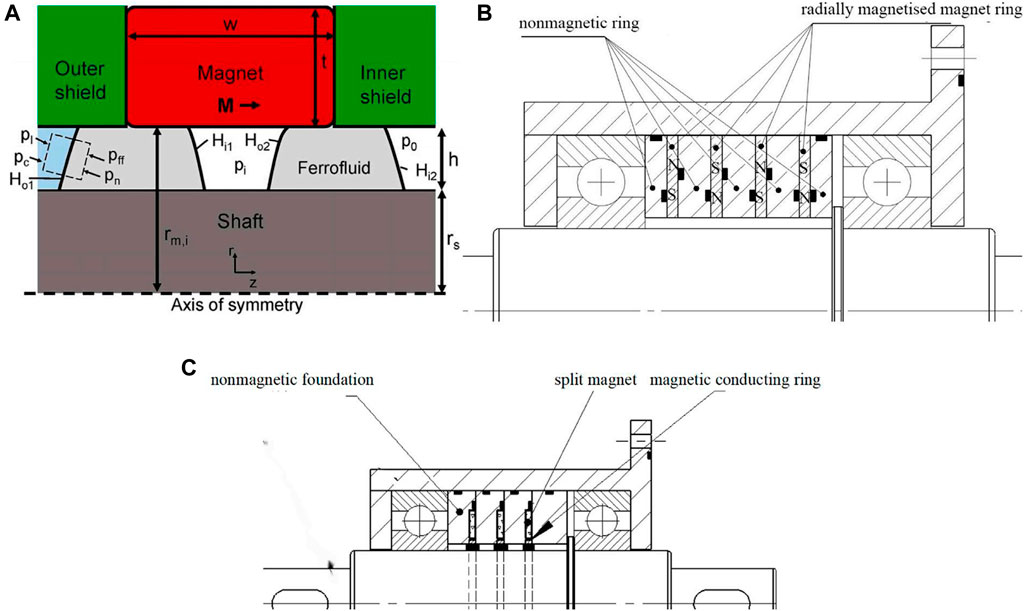
FIGURE 1. Structure of the FF seal. (A) FF seal proposed by Karoen van der Wal etc (van der Wal et al., 2020); (B) FF radial-charged seal; (C) FF split magnet seal.
From the Bernoulli equation of FF and the corresponding assumption, the total seal pressure of the FF seal can be approximately expressed as (Li et al., 2004; Li, 2010; Yuichi et al., 2015; Yang and Li, 2016b; Li and Hao, 2018; Zhang et al., 2018)
where n is the number of seal stages, and pi is the seal pressure of stage i in the FF seal. The seal pressure provided by each seal stage could be approximately considered identical; Himin and Himax are the minimum and maximum magnetic field strength under stage i of the seal gap, respectively;
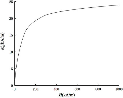
FIGURE 2. Magnetization curve of the coal-based FF.
As shown in Figure 3A, it is a classic rectangular pole teeth structure of FF seal whose seal gap (distance between pole teeth and shaft) is 0.1 mm. With this gap confirmed, we set the pole teeth width Lt, pole teeth distance Ls, and pole teeth height Lh as 0.2 mm,、0.8 mm,、and 0.7 mm, respectively. The design theory has been successfully applied to many FF seals (Chi, 1993; Zhao et al., 2006; Yang et al., 2013), which are well sealed and highly reliable under many situations. Due to their small size, pole teeth have poor processability and quality. The main shaft has unavoidable radial runout; therefore, when the seal gap is changing, the pole teeth get hurt easily and have poor sealing performance. So we let the newly structured FF radial-charged seal remove the pole teeth, as shown in Figure 3B. To solve the ring magnets’ problems of processability, installation, and uneven magnetization, we replaced ring magnets with split magnets. To install split magnets stably, we adjusted the structure of the nonmagnetic ring to a nonmagnetic foundation, as shown in Figures 3C,D, which can not only raise the magnetic field but also meet the positioning needs of split magnets.
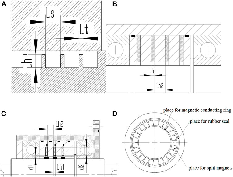
FIGURE 3. Structural size of the FF seal. (A) Classic FF seal; (B) FF radial-charged seal; (C) FF split magnet seal; (D) nonmagnetic foundation.
At first, we found out the better structural parameter of the FF seal by FEA, as shown in Figure 4 and Table 1. Table 1 shows the structural size of the classic FF seal, the FF radial-charged seal, and the FF split magnet seal. We set the shaft of the seal as 30 mm to make the calculation more accurate and reduce the calculation time. Then, we used FEA to compare the seal pressure of these structures and analyze the best choice of split magnets, in order to get the optimal structural design of the FF split magnet seal. Here, we mainly discussed the diameter or thickness Lh1 of the split magnet, the space Lh2 between split magnets, and the length Lh3 of the split magnet. In order to reduce demagnetization, the magnet cross section of the working site should be designed as a square. We simulated the FF cuboid magnet seal with Lh1 = Lh3 = 3 mm and Lh2 = 3 mm under the sealing gap of 0.1 mm that has 0.1 MPa seal capacity. We considered such a structure as an example and used the control variable method to discuss the effects of Lh1 and Lh2 on seal capacity. The results are shown in Figure 4. Considering the restrictive condition of process accuracy, the strength of the wall between magnets, and magnet size restriction, we take Lh1 = 4 mm and Lh2 = 2 mm. Twenty small magnets can be installed on one nonmagnetic foundation.
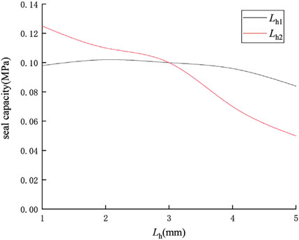
FIGURE 4. Relationship between seal capacity and Lh.
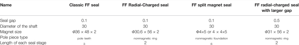
TABLE 1. Relevant size (mm).
Then, according to the parameter, we processed the FF split magnet seal device to test its seal capacity. During the test, the air pressure is delivered from a pressure cylinder and adjusted by a pressure-reducing valve. The pressure in the sealed chamber is measured with a pressure gauge to range from 0 to 2 MPa. The rotational speed of the motor is controlled and displayed by using a controller. (Li et al., 2021). To examine cuboid magnet and cylindrical magnet seal capacity, the experimental study on the FF split magnet seal is divided into two parts: a static pressure test and a dynamic pressure test. In the experiment table, the two kinds of magnets installed on a nonmagnetic foundation and their relevant sizes are shown in Figure 5 and Table 1, respectively. The device consists of a nonmagnetic shell, a shaft, bearings, nonmagnetic foundations, split magnets, and ferrofluids. About the choice of materials, magnetic parts, such as the shaft and the pole shoes, are made of magnetic materials, 2Cr13 here. Nonmagnetic sections, such as the nonmagnetic ring and the shell, are made of NdFeB with a relative permeability of 1.05 and a coercive force of 8.9 e5. The magnetization of the radial-charged ring magnet is shown in Figure 5.
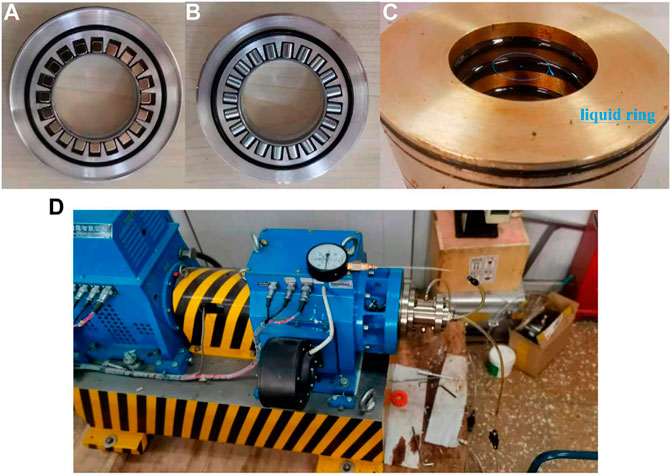
FIGURE 5. Experimental device.(A) Cuboid magnets installed on nonmagnetic foundation; (B) cylindrical magnets installed on nonmagnetic foundation; (C) seal ring injected with FFs; (D) rotary seal experiment table.
For the classic FF seal and FF radial-charged seal, we used SolidWorks to draw the core of the sealing device of the aforementioned structure scheme. Then, we imported it to the Maxwell 2D module and set the geometry module as cylindrical about Z. The magnetization direction of radial-charged ring magnets is r in the cylindrical coordinate system. According to the Maxwell FEA, we can optimize the seal structure. It is not rigorous to analyze the FF split magnet seal by the Maxwell 2D module. So we decided to use the Maxwell 3D module to analyze, which can not only analyze the stability of FF “O"-shaped seals but also find the difference between the cuboid and cylindrical magnet, which are the most commonly used split magnets. The seal model, contour plot, and magnetic lines distribution are respectively shown in Figures 6–8. The classic FF seal, FF radial-charged seal, FF cuboid magnet seal, and FF cylindrical magnet seal are respectively shown in Figures (A), (B), (C), (D). In Figure 6, the blue part represents the magnet parts, the orange part represents the magnetic parts, and the gray represents the non-magnetic parts. Compared to Figures 7C,D, we can find the magnetic line distribution of a cuboid magnet is more centralized than a cylindrical magnet. So we can guess the magnetic fluid of the FF cuboid magnet seal is stronger and more uniform.
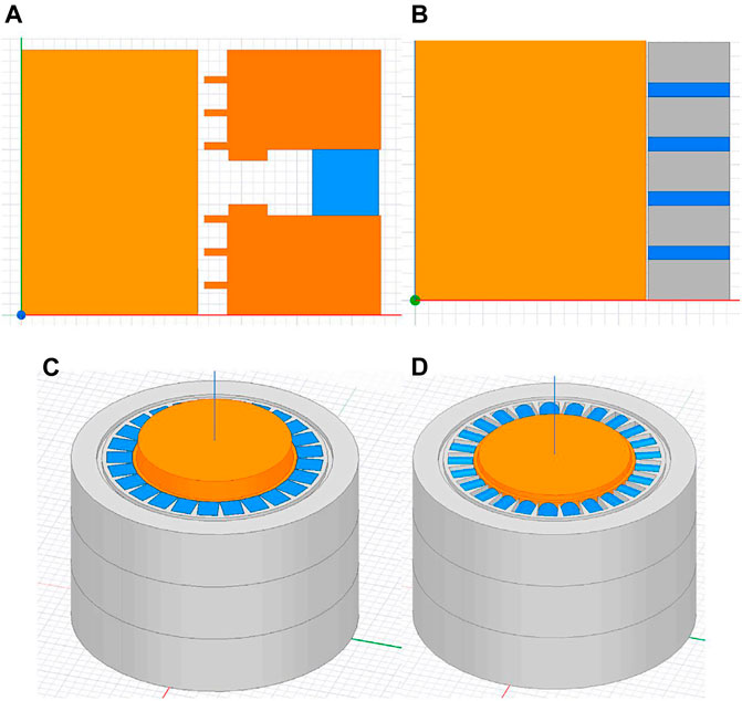
FIGURE 6. Figure of the seal model. (A) Classic FF seal; (B) FF radial-charged seal; (C) FF cuboid magnet seal; (D) FF cylindrical magnet seal.
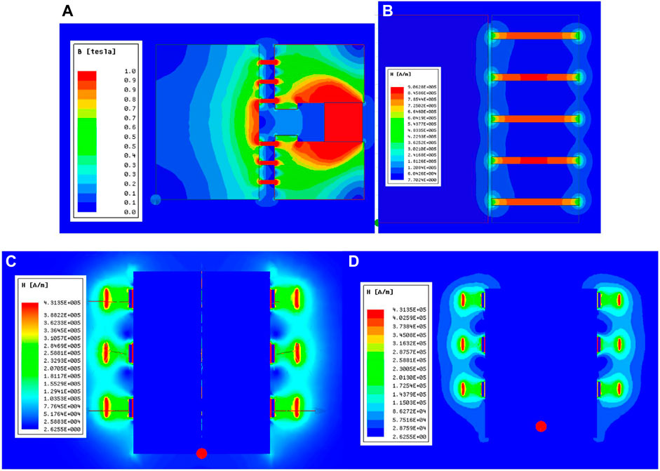
FIGURE 7. Contour plot. (A) Classic FF seal; (B) FF radial-charged seal; (C) FF cuboid magnet seal; (D) FF cylindrical magnet seal.
According to simulation and calculation, we get the magnetic field strength curve of all kinds of FF seals, which is shown in Figure 8. According to the aforementioned formula and the relevant knowledge of the magnetic fluid seal, in order to meet the saturation of the magnetic fluid, we observed that the magnetic field strength in the working gap, where magnetic fluid exists, should be greater than the 200 kA/m. In this condition, the difference in the axial magnetic field strength determines the maximum seal pressure. Then, we treated the simulation results by formula (2). The results are shown in Figure 8 and Table 2. From Figure 9, it is obvious to find out that the magnetic field strength curves in the seal gap of these new structures of FF seals are both similar to those of the classic FF seal, which has a significant magnetic field strength gradient. Therefore, we can preliminarily consider that these seals need to be analyzed. The seal pressure is calculated and analyzed in the following. In order to analyze the influence of the magnetic rings on the magnetic field distribution and choose the better split magnets between the cylindrical magnet and the cuboid magnet, we set two arcs at the mid and the edge of magnets in the seal gap to analyze the degree of magnetic field uniformity, which is shown in Figure 10. The results are shown in Figures 11,12, whose abscissa indicates the arc angle rotating around the shaft.
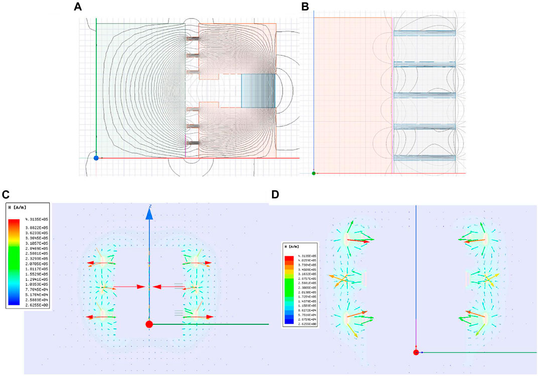
FIGURE 8. Distribution map of magnetic lines. (A) Classic FF seal; (B) FF radial-charged seal; (C) FF cuboid magnet seal; (D) FF cylindrical magnet seal.
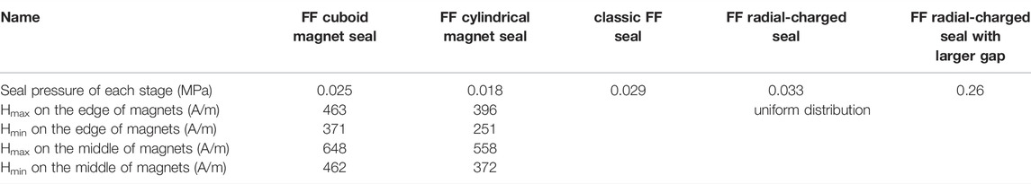
TABLE 2. Simulation result.
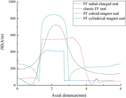
FIGURE 9. Magnetic field strength curve of the seal gap of different structures of the magnetic fluid seal.
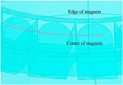
FIGURE 10. Arcs in the seal gap.
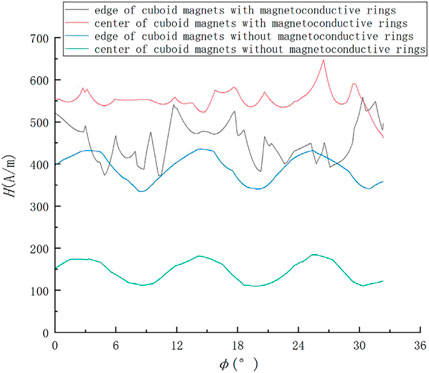
FIGURE 11. Magnetic field in the seal gap with magnetic rings or not.
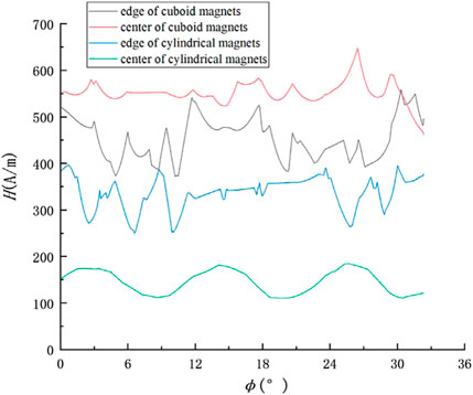
FIGURE 12. Magnetic field in the seal gap with a different type of split magnets.
In terms of the experiment, the static pressure resistance experiment of the FF cuboid magnet seal and the FF cylindrical magnet seal were first carried out. Then, the experimental results and the simulation results are shown in Figure 13. The structure of the conductive ring is very important. If the conductive ring is removed, the small magnet will attach to the shaft and cannot form a uniform magnetic fluid o-ring in the sealing gap. So the pressure capacity of the seal group without a conductive ring is 0. In order to prevent the leakage from the gap between the magnets and conductive rings or magnets and nonmagnetic foundations, we used silicone sealant to fill these gaps. A rotational pressure resistance experiment for the FF cuboid magnet seal was performed subsequently. But no matter how we adjust the sealing device, it seems to have a little gap between the shaft and the ring, and the starting torque was much larger than we imagined. We cannot find any rational result in the rotational experiment.
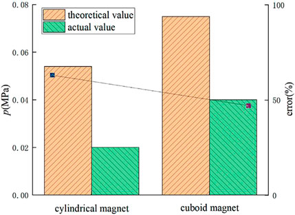
FIGURE 13. Results of the static seal capacity experiment.
In this study, we analyzed the magnetic field of the classic FF seal, FF radial-charged seal, FF cuboid magnet seal, and FF cylindrical magnet seal in the seal gap. 1) From the magnetic field strength curve of the seal gap in Figure 9, we can find that the new structures of FF radial-charged seal and the FF split magnet seal can form a magnetic field with an axial gradient in the seal gap. From formula (2), the magnetic field strength gradient can fix FF in the seal gap, which offers the seal pressure. According to the static experiment result in Figure 13, the seal capacity of the FF cuboid magnet seal and the FF cylindrical magnet seal can be proved. 2) From Table 2, in terms of seal pressure, the FF radial-charged seal is larger than the other two FF split magnet seals. In Figure 11, the magnetic field intensity along the split magnets in the seal gap has regular fluctuation. The reason for this phenomenon is the presence of small gaps between the split magnets, which is greatly different from ring magnets. If we do not use the magnetic ring, the small magnets will stick to the shaft and lead to the leakage of the seal. So we set a magnetic ring between FF and magnets to address these problems. The design allows the seal to form a uniform and dense FF “O"-shaped sealing rings in the seal gap. 3) According to the seal size in Table 2, compared with the FF cuboid magnet seal and the FF cylindrical magnet seal, the FF radial-charged seal has more seal stages in the same space, larger seal pressure, and stability. It seems that the FF radial-charged seal is the best choice to solve the problems of the radial beating of the main shaft and low seal pressure under the large gap. However, the ring magnet is facing the problems of processability, installation, and uneven magnetization, so the seal pressure will drop or even fail. For seal, the seal pressure is not an absolute criterion, but how to meet the actual needs is more important. 4) In Figure 13, we can find the FF cuboid magnet seal has a larger seal capacity than the FF cylindrical magnet seal. Meanwhile, the error of the latter is much larger than the former. The reason for the difference in error is probably that the FF liquid ring quality of the FF cylindrical magnet seal is poor. It can also be proved by Table 2 and Figure 12. So we can consider that the FF cuboid magnet seal is the better choice than the FF cylindrical magnet seal.
1) According to FEA, we find that the three new structures have a certain seal pressure.
2) According to the experiments, the FF cuboid magnet seal has a larger seal capacity than the FF cylindrical magnet seal. It has solved the installation difficulties, vulnerability of pole teeth, and poor seal performance of classic FF seals in engineering. It has solved the problems of processability, installation, and uneven magnetization from ring magnets. Meanwhile, its seal pressure can meet the needs of many situations.
3) Although the nonmagnetic foundation of the FF cuboid magnet seal and the FF cylindrical magnet seal is complex, it can bring split magnets and magnetic rings before installation, which can reduce installation difficulties. However, due to the disadvantage of its large size, the FF split magnet seal has been better applied to the shaft with a large sealing space. So it is essential to analyze how to raise the utilization of seal space.
For future research directions: in Figure 13, the error in comparison between the actual value and theoretical value is larger than 40%, which is too high to convince us that the seal in the experiment is the best one. Along with the situation in the rotational experiment, we can find the problems with the structure. Due to the uneven distribution of the silicone sealant, there is a fixed problem with the magnetic ring. In future research, we will improve the structure of multiple small magnetic rings into the integrated magnetic ring and finish the rotational seal experiment.
The original contributions presented in the study are included in the article/Supplementary Material; further inquiries can be directed to the corresponding author.
Under the guidance of LD and ZZ, the author finished the manuscript.
The authors declare that the research was conducted in the absence of any commercial or financial relationships that could be construed as a potential conflict of interest.
All claims expressed in this article are solely those of the authors and do not necessarily represent those of their affiliated organizations, or those of the publisher, the editors, and the reviewers. Any product that may be evaluated in this article, or claim that may be made by its manufacturer, is not guaranteed or endorsed by the publisher.
Li, D. C., Zhang., H. N., and Zhang, Z. L.. Study on Magnetic Fluid Static Seal of Large Gap, Kem, 512-515. 2012. 1448-1454. doi:10.4028/www.scientific.net/kem.512-515.1448
Du, C., and Lin, H. (2006). Effect of the Magnetoconductive Pole Piece Structure on the Magnetic Fluid Seal Capacity[J]. Chem. Equip. Technol. (02), 71–73. doi:10.3969/j.issn.10077251.2006.02.021
He, X., Li, D., and Wang, H. (2014). Effects of Gravity on the Sealing Properties of Magnetic Fluids[J]. Chin. J. Vac. Sci. Technol. 34 (11), 1160–1163. doi:10.13922/j.cnki.cjovst.2014.11.05
He, X., Miao, Y., Wang, L., and Li, Z. (2019). Latest Development in Sealing of Liquid Medium with Magnetic Fluid[J]. Chin. J. Vac. Sci. Technol. 39 (05), 361–366. doi:10.13922/j.cnki.cjovst.2019.05.01
Li, D., and Hao, D. (2018). Major Problems and Solutions in Applications of Magnetic Fluid Rotation Seal[J]. Chin. J. Vac. Sci. Technol. 38 (07), 564–574. doi:10.13922/j.cnki.cjovst.2018.07.04
Li, D., Xu, H., He, X., and Lan, H. (2004). Study on the Magnetic Fluid Sealing for Dry Roots Pump[J]. J. Magnetism Magnetic Mater. 289, 419–422. doi:10.1016/j.jmmm.2004.11.118
Li, D., and Yang, W. (2010). Experimental Study on Static Sealing of Magnetic Liquid with Large Diameter and Large Gap [J]. Acta Armamentarii 31 (03), 355–359.
Li, Z., Li, S., Wang, X., and Li, D. (2021). Numerical Simulation and Experimental Study on Magnetorheological Fluid Seals with Flexible Pole Pieces[J]. IEEE Trans. MAGNETICS 57 (10). doi:10.1109/tmag.2021.3094868
Liu, J., Li, D., and Zhang, Z. (2021). Magnet Design and Anti-pressure Analysis of New Magnetic Fluid Seal[J]. J. Beijing Jiaot. Univ. 42 (3), 1–7. (in Chinese). doi:10.11860/j.issn.1673-0291.20210035
Luo, E. (1993). The Cutting Point Effect and its Mathematical Expressions [J]. Coll. Phys. (06), 20–25.
Raj, K., and Boulton, R. J. (1987). Ferrofluids a Properties and Applications[J]. Mater. Des. 8 (4). doi:10.1016/0261-3069(87)90139-7
Szczech, M., and Horak, W. (2017). Numerical Simulation and Experimental Validation of the Critical Pressure Value in Ferromagnetic Fluid Seals[J]. IEEE Trans. Magnetics 53 (7), 4600601–4600605. doi:10.1109/tmag.2017.2672922
van der Wal, K., van Ostayen, R. A. J., and Lampaert, S. G. E. (2020). Ferrofluid Rotary Seal with Replenishment System for Sealing Liquids. Tribol. Int. 150, 106372. doi:10.1016/j.triboint.2020.106372
Wang, Z. A Theoretical and Experimental Study on Mechanical-Magnetic Fluid Combined Sealing[D]. Beijing: Beijing Jiaotong University.
Wang, Z., Li, D., Zhang, Y., Gao, Y., and Neumann, H. R. (2019). The Pressure Loading Process Among Stages of Magnetic Fluid Seal in Aqueous Environment[J]. Tribol. Trans. 62 (4). doi:10.1080/10402004.2019.1597241
Yang, X., and Li, D. C. (2016). Experimental Investigation of Diverging Stepped Magnetic Fluid Seals with Large Sealing Gap[J]. Int. J. Appl. Electromagn. Mech. 50 (3), 407–415. doi:10.3233/JAE-150117
Yang, X., and Li, D. C. (2016). Design and Experimental Study on Large Gap Polymerization Stair Type Magnetic Fluid Seal[J]. Chin. J. Vac. Sci. Technol. 36 (03), 258–262. doi:10.13922/j.cnki.cjovst.2016.03.02
Yang, X., Li, D., and Yang, W. (2012). Fluid Sealed Magnetic Road Design and Magnetic Field Analysis [J]. J. Vac. Sci. Technol. 32 (10), 919–922.
Yang, X., Li, Z., and Li, D. (2013). Numerical and Experimental Study of Magnetic Fluid Seal with Large Sealing Gap and Multiple Magnetic Sources[J]. Sci. China Technol. Sci. 56 (11). doi:10.1007/s11431-013-5365-4
Yuichi, M., Hiroshi, S., Hayato, Y., and Hidenori, S. (2015). Magnetic Fluid Seal for Linear Motion System with Gravity Compensator[J]. Procedia CIRP 33, 581–586. doi:10.1016/j.procir.2015.06.088
Zhang, Y., Li, D., Chen, Y., and Li, Z. (2018). A Comparative Study of Ferrofluid Seal and Magnetorheological Fluid Seal[J]. IEEE Trans. MAGNETICS 54 (12). doi:10.1109/tmag.2018.2868298
Keywords: ferrofluid seal, experimental study, finite element analysis, without pole shoes, split magnet
Citation: Liu J, Li D and Zhang Z (2022) Experimental Study and Simulation on the Seal Pressure of a Ferrofluid Seal Using Radial-Charged Magnets. Front. Mater. 9:879699. doi: 10.3389/fmats.2022.879699
Received: 20 February 2022; Accepted: 28 April 2022;
Published: 13 June 2022.
Edited by:
Marcelo J. Dapino, The Ohio State University, United StatesReviewed by:
Xingzhe Wang, Lanzhou University, ChinaCopyright © 2022 Liu, Li and Zhang. This is an open-access article distributed under the terms of the Creative Commons Attribution License (CC BY). The use, distribution or reproduction in other forums is permitted, provided the original author(s) and the copyright owner(s) are credited and that the original publication in this journal is cited, in accordance with accepted academic practice. No use, distribution or reproduction is permitted which does not comply with these terms.
*Correspondence: Jiawei Liu , bGlkZWNhaUB0c2luZ2h1YS5tYWlsLmVkdS5jbg==
Disclaimer: All claims expressed in this article are solely those of the authors and do not necessarily represent those of their affiliated organizations, or those of the publisher, the editors and the reviewers. Any product that may be evaluated in this article or claim that may be made by its manufacturer is not guaranteed or endorsed by the publisher.
Research integrity at Frontiers
Learn more about the work of our research integrity team to safeguard the quality of each article we publish.